In order to promote public education and public safety, equal justice for all, a better informed citizenry, the rule of law, world trade and world peace, this legal document is hereby made available on a noncommercial basis, as it is the right of all humans to know and speak the laws that govern them.

A Member of the International Code Family®
Become a Building Safety Professional Member and Learn More about the Code Council
GO TO WWW.ICCSAFE.ORG for All Your Technical and Professional Needs Including:
2012 International Fuel Gas Code®
First Printing: April 2011
ISBN: 978-1-60983-049-6 (soft-cover edition)
ISBN: 978-1-60983-048-9 (loose-leaf edition)
COPYRIGHT© 2011
by
INTERNATIONAL CODE COUNCIL, INC.
ALL RIGHTS RESERVED. This 2012 International Fuel Gas Code® is a copyrighted work owned by the International Code Council, Inc. Without advance written permission from the copyright owner, no part of this book may be reproduced, distributed, or transmitted in any form or by any means, including, without limitation, electronic, optical or mechanical means (by way of example, and not limitation, photocopying, or recording by or in an information storage retrieval system). For information on permission to copy material exceeding fair use, please contact: Publications, 4051 West Flossmoor Road, Country Club Hills, IL 60478. Phone 1-888-ICC-SAFE (422-7233).
Trademarks: “International Code Council,” the “International Code Council” logo and the “International Fuel Gas Code” are trademarks of the International Code Council, Inc.
Material designated IFGS
by
AMERICAN GAS ASSOCIATION
400 N. Capitol Street, N.W. • Washington, DC 20001
(202) 824-7000
Copyright © American Gas Association, 2011. All rights reserved.
PRINTED IN THE U.S.A.
iiInternationally, code officials recognize the need for a modern, up-to-date fuel gas code addressing the design and installation of fuel gas systems and gas-fired appliances through requirements emphasizing performance. The International Fuel Gas Code®, in this 2012 edition, is designed to meet these needs through model code regulations that safeguard the public health and safety in all communities, large and small.
This comprehensive fuel gas code establishes minimum regulations for fuel gas systems and gas-fired appliances using prescriptive and performance-related provisions. It is founded on broad-based principles that make possible the use of new materials and new fuel gas system and appliance designs. This 2012 edition is fully compatible with all of the International Codes® (l-Codes®) published by the International Code Council (ICC)®, including the International Building Code®, International Energy Conservation Code®, International Existing Building Code®, International Fire Code®, International Green Construction Code® (to be available March 2012), International Mechanical Code®, ICC Performance Code®, International Plumbing Code®, International Private Sewage Disposal Code®, International Property Maintenance Code®, International Residential Code®, International Swimming Pool and Spa Code® (to be available March 2012), International Wildland-Urban Interface Code® and International Zoning Code®.
The International Fuel Gas Code provisions provide many benefits, among which is the model code development process that offers an international forum for fuel gas technology professionals to discuss performance and prescriptive code requirements. This forum provides an excellent arena to debate proposed revisions. This model code also encourages international consistency in the application of provisions.
The first edition of the International Fuel Gas Code (1997) was the culmination of an effort initiated in 1996 by a development committee appointed by ICC and consisting of representatives of the three statutory members of the International Code Council at that time, including: Building Officials and Code Administrators International, Inc. (BOCA), International Conference of Building Officials (ICBO) and Southern Building Code Congress International (SBCCI) and the gas industry. The intent was to draft a comprehensive set of regulations for fuel gas systems and gas-fired appliances consistent with and inclusive of the scope of the existing mechanical, plumbing and gas codes. Technical content of the latest model codes promulgated by BOCA, ICBO, SBCCI and ICC and the National Fuel Gas Code (ANSI Z223.1) was utilized as the basis for the development. This 2012 edition presents the code as originally issued, with changes reflected in subsequent editions through 2009, and with code changes approved through the ICC Code Development Process through 2010 and standard revisions correlated with ANSI Z223.1-2012. A new edition such as this is promulgated every three years.
This code is founded on principles intended to establish provisions consistent with the scope of a fuel gas code that adequately protects public health, safety and welfare; provisions that do not unnecessarily increase construction costs; provisions that do not restrict the use of new materials, products or methods of construction; and provisions that do not give preferential treatment to particular types or classes of materials, products or methods of construction.
The International Fuel Gas Code is segregated by section numbers into two categories - “code” and “standard” - all coordinated and incorporated into a single document. The sections that are “code” are designated by the acronym “IFGC” next to the main section number (e.g., Section 101). The sections that are “standard” are designated by the acronym “IFGS” next to the main section number (e.g., Section 304). A subsection may be individually redesignated as an “IFGS” section where it is located under an “IFGC” main section.
iiiThe International Fuel Gas Code is available for adoption and use by jurisdictions internationally. Its use within a governmental jurisdiction is intended to be accomplished through adoption by reference in accordance with proceedings establishing the jurisdiction’s laws. At the time of adoption, jurisdictions should insert the appropriate information in provisions requiring specific local information, such as the name of the adopting jurisdiction. These locations are shown in bracketed words in small capital letters in the code and in the sample ordinance. The sample adoption ordinance on page ix addresses several key elements of a code adoption ordinance, including the information required for insertion into the code text.
The International Fuel Gas Code is kept up to date through the review of proposed changes submitted by code enforcing officials, industry representatives, design professionals and other interested parties. Proposed changes are carefully considered through an open code development process in which all interested and affected parties may participate. The code development process of the International Fuel Gas Code is slightly different than the process for the other International Codes.
Proposed changes to text designated “IFGC” are subject to the ICC Code Development Process. For more information regarding the code development process, contact the Codes and Standards Development Department of the International Code Council.
Proposed changes to text designated as “IFGS” are subject to the standards development process which maintains the National Fuel Gas Code (ANSI Z223.1). For more information regarding the standards development process, contact the American Gas Association (AGA) at 400 N. Capitol Street, N.W., Washington, DC 20001.
While the development procedure of the International Fuel Gas Code ensures the highest degree of care, the ICC, its members, the AGA and those participating in the development of this code do not accept any liability resulting from compliance or noncompliance with the provisions because the ICC, its founding members and the AGA do not have the power or authority to police or enforce compliance with the contents of this code. Only the governmental body that enacts the code into law has such authority.
In each code development cycle, proposed changes to the code are considered at the Code Development Hearings by the International Fuel Gas Code Development Committee, whose action constitutes a recommendation to the voting membership for final action on the proposed change. Proposed changes to a code section that has a number beginning with a letter in brackets are considered by a different code development committee. For example, proposed changes to code sections that have [B] in front of them (e.g., [B] 302.1) are considered by the appropriate International Building Code Development Committee (IBC-Structural) at the code development hearings.
The content of sections in this code that begin with a letter designation is maintained by another code development committee in accordance with the following:
[A] = Administrative Code Development Committee;
[B] = International Building Code Development Committee (IBC—Fire Safety, General, Means of Egress or Structural);
[M] = International Mechanical Code Development Committee; and
[F] = International Fire Code Development Committee.
ivNote that, for the development of the 2015 edition of the l-Codes, there will be two groups of code development committees and they will meet in separate years. The groupings are as follows:
| Group A Codes (Heard in 2012, Code Change Proposals Deadline: January 3,2012) | Group B Codes (Heard in 2013, Code Change Proposals Deadline: January 3, 2013) |
|---|---|
| International Building Code | Administrative Provisions (Chapter 1 all codes except IRC and ICCPC, administrative updates to currently referenced standards, and designated definitions) |
| International Fuel Gas Code | International Energy Conservation Code |
| International Mechanical Code | International Existing Building Code |
| International Plumbing Code | International Fire Code |
| International Private Sewage Disposal Code | International Green Construction Code |
| ICC Performance Code | |
| International Property Maintenance Code | |
| International Residential Code | |
| International Swimming Pool and Spa Code | |
| International Wildland-Urban Interface Code | |
| International Zoning Code |
Code change proposals submitted for code sections that have a letter designation in front of them will be heard by the respective committee responsible for such code sections. Because different committees will meet in different years, it is possible that some proposals for this code will be heard by a committee in a different year than the year in which the primary committee for this code meets.
For example, every section of Chapter 1 of this code is designated as the responsibility of the Administrative Code Development Committee, and that committee is part of the Group B code hearings. This committee will conduct its code development hearing in 2013 to consider all code change proposals for Chapter 1 of this code and proposals for Chapter 1 of all l-Codes. Therefore, any proposals received for Chapter 1 of this code will be deferred for consideration in 2013 by the Administrative Code Development Committee.
Another example is Section 707 of this code which is designated as the responsibility of the International Fire Code Development Committee. This committee will conduct its code development hearing in 2013 to consider code change proposals in its purview, which includes any proposals to Section 707.
In some cases, another committee in Group A will be responsible for a section of this code. For example, Section 306.1 has a [M] in front of the numbered section, indicating that this section of the code is the responsibility of the International Mechanical Code Development Committee. The International Mechanical Code is in Group A; therefore, any code change proposals to this section will be due before the Group A deadline of January 3, 2012, and these code change proposals will be assigned to the International Mechanical Code Development Committee for consideration.
It is very important that anyone submitting code change proposals understand which code development committee is responsible for the section of the code that is the subject of the code change proposal. For further information on the code development committee responsibilities, please visit the ICC web site at www.iccsafe.org/scoping.
vSolid vertical lines in the margins within the body of the code indicate a technical change from the requirements of the 2009 edition. Deletion indicators in the form of an arrow ( ) are provided in the margin where an entire section, paragraph, exception or table has been deleted or an item in a list of items or in a table has been deleted.
Selected terms set forth in Chapter 2, Definitions, are italicized where they appear in code text. Such terms are not italicized where the definition set forth in Chapter 2 does not impart the intended meaning in the use of the term. The terms selected have definitions which the user should read carefully to facilitate better understanding of the code.
viThe IFGC is a model code that regulates the design and installation of fuel gas distribution piping and systems, appliances, appliance venting systems, combustion air provisions, gaseous hydrogen systems and motor vehicle gaseous-fuel-dispensing stations. The definition of fuel gas includes natural, liquefied petroleum and manufactured gases and mixtures of these gases.
The purpose of the code is to establish the minimum acceptable level of safety and to protect life and property from the potential dangers associated with the storage, distribution and usage of fuel gases and the byproducts of combustion of such fuels. The code also protects the personnel that install, maintain, service and replace the systems and appliances addressed by this code.
With the exception of Section 401.1.1, the IFGC does not address utility-owned piping and equipment (i.e., anything upstream of the point of delivery). See the definition of “Point of delivery” and Section 501.8 for other code coverage exemptions.
The IFGC is primarily a specification-oriented (prescriptive) code with some performance-oriented text. For example, Section 503.3.1 is a performance statement, but Chapter 5 contains prescriptive requirements that will cause Section 503.3.1 to be satisfied.
The IFGC applies to all occupancies including one- and two-family dwellings and townhouses. The IRC is referenced for coverage of one- and two-family dwellings and townhouses; however, in effect, the IFGC provisions are still applicable because the fuel gas chapter in the IRC (Chapter 24) is composed entirely of text extracted from the IFGC. Therefore, whether using the IFGC or the IRC, the fuel gas provisions will be identical. The IFGC does not apply to piping systems that operate at pressures in excess of 125 psig for natural gas and 20 psig for LP-gas (note exception in Section 402.6).
The general Section 105.2 and the specific Sections 304.8, 402.3, 503.5.5 and 503.6.9 allow combustion air provisions, pipe sizing and chimney and vent sizing to be performed by approved engineering methods as alternatives to the prescriptive methods in the code.
The format of the IFGC allows each chapter to be devoted to a particular subject, with the exception of Chapter 3, which contains general subject matters that are not extensive enough to warrant their own independent chapter.
Chapter 1 Scope and Administration. Chapter 1 establishes the limits of applicability of the code and describes how the code is to be applied and enforced. A fuel gas code, like any other code, is intended to be adopted as a legally enforceable document, and it cannot be effective without adequate provisions for its administration and enforcement. The provisions of Chapter 1 establish the authority and duties of the code official appointed by the jurisdiction having authority and also establish the rights and privileges of the design professional, contractor and property owner.
Chapter 2 Definitions. Chapter 2 is the repository of the definitions of terms used in the body of the code. Codes are technical documents and every word, term and punctuation mark can impact the meaning of the code text and the intended results. The code often uses terms that have a unique meaning in the code and the code meaning can differ substantially from the ordinarily understood meaning of the term as used outside of the code.
The terms defined in Chapter 2 are deemed to be of prime importance in establishing the meaning and intent of the code text that uses the terms. The user of the code should be familiar with and consult this chapter because the definitions are essential to the correct interpretation of the code and because the user may not be aware that a term is defined.
Chapter 3 General Regulations. Chapter 3 contains broadly applicable requirements related to appliance location and installation, appliance and systems access, protection of structural elements and clearances to combustibles, among others. This chapter also covers combustion air provisions for gas-fired appliances.
viiChapter 4 Gas Piping Installations. Chapter 4 covers the allowable materials for gas piping systems and the sizing and installation of such systems. It also covers pressure regulators, appliance connections and overpressure protection devices. Gas piping systems are sized to supply the maximum demand while maintaining the supply pressure necessary for safe operation of the appliances served.
Chapter 5 Chimneys and Vents. Chapter 5 regulates the design, construction, installation, maintenance, repair and approval of chimneys, vents, venting systems and their connections to gas-fired appliances. Properly designed chimneys, vents and venting systems are necessary to conduct to the outdoors the flue gases produced by the combustion of fuels in appliances. The provisions of this chapter are intended to minimize the hazards associated with high temperatures and potentially toxic and corrosive combustion gases. This chapter addresses all of the factory-built and site-built chimneys, vents and venting systems used to vent all types and categories of appliances. It also addresses direct-vent appliances, integral vent appliances, side-wall mechanically vented appliances and exhaust hoods that convey the combustion byproducts from cooking and other process appliances.
Chapter 6 Specific Appliances. Chapter 6 addresses specific appliances that the code intends to regulate. Each main section applies to a unique type of gas-fired appliance and specifies the product standards to which the appliance must be listed. The general requirements found in the previous Chapters 1 through 5 also apply and the sections in Chapter 6 add the special requirements that are specific to each type of appliance.
Chapter 7 Gaseous Hydrogen Systems. Chapter 7 is specific to gaseous hydrogen generation, storage, distribution and utilization systems, appliances and equipment. Note that hydrogen is not within the definition of “Fuel gas,” but it is, nonetheless, commonly used as a fuel for fuel-cell power generation and fuel-cell powered motor vehicles. The scope of Chapter 7 is not limited to any particular use of hydrogen (see Sections 633 and 635). Hydrogen systems have unique potential hazards because of the specific gravity of the gas, its chemical effect on materials and the fact that it is not odorized.
Chapter 8 Referenced Standards. Chapter 8 lists all of the product and installation standards and codes that are referenced throughout Chapters 1 through 7. As stated in Section 102.8, these standards and codes become an enforceable part of the code (to the prescribed extent of the reference) as if printed in the body of the code. Chapter 8 provides the full title and edition year of the standards and codes in addition to the address of the promulgators and the section numbers in which the standards and codes are referenced.
Appendix A Sizing and Capacities of Gas Piping. This appendix is informative and not part of the code. It provides design guidance, useful facts and data and multiple examples of how to apply the sizing tables and sizing methodologies of Chapter 4.
Appendix B Sizing of Venting Systems Serving Appliances Equipped with Draft Hoods, Category I Appliances and Appliances Listed for Use with Type B Vents. This appendix is informative and not part of the code. It contains multiple examples of how to apply the vent and chimney tables and methodologies of Chapter 5.
Appendix C Exit Terminals of Mechanical Draft and Direct-vent Venting Systems. This appendix is informative and not part of the code. It consists of a figure and notes that visually depict code requirements from Chapter 5 for vent terminals with respect to the openings found in building exterior walls.
Appendix D Recommended Procedure for Safety Inspection of an Existing Appliance Installation. This appendix is informative and not part of the code. It provides recommended procedures for testing and inspecting an appliance installation to determine if the installation is operating safely and if the appliance is in a safe condition.
viiiThe International Codes are designed and promulgated to be adopted by reference by legislative action. Jurisdictions wishing to adopt the 2012 International Fuel Gas Code as an enforceable regulation governing fuel gas systems and gas-fired appliances should ensure that certain factual information is included in the adopting legislation at the time adoption is being considered by the appropriate governmental body. The following sample adoption legislation addresses several key elements, including the information required for insertion into the code text.
A[N] [ORDINANCE/STATUTE/REGULATION] of the [JURISDICTION] adopting the 2012 edition of the International Fuel Gas Code, regulating and governing fuel gas systems and gas-fired appliances in the [JURISDICTION]; providing for the issuance of permits and collection of fees therefor; repealing [ORDINANCE/STATUTE/REGULATION] No. _____ of the [JURISDICTION] and all other ordinances or parts of laws in conflict therewith.
The [GOVERNING BODY] of the [JURISDICTION] does ordain as follows:
Section 1. That a certain document, three (3) copies of which are on file in the office of the [TITLE OF JURISDICTION’S KEEPER OF RECORDS] of [NAME OF JURISDICTION], being marked and designated as the International Fuel Gas Code, 2012 edition, including Appendix Chapters [FILL IN THE APPENDIX CHAPTERS BEING ADOPTED] (see International Fuel Gas Code Section 101.3, 2012 edition), as published by the International Code Council, be and is hereby adopted as the Fuel Gas Code of the [JURISDICTION], in the State of [STATE NAME] for regulating and governing fuel gas systems and gas-fired appliances as herein provided; providing for the issuance of permits and collection of fees therefor; and each and all of the regulations, provisions, penalties, conditions and terms of said Fuel Gas Code on file in the office of the [JURISDICTION] are hereby referred to, adopted, and made a part hereof, as if fully set out in this legislation, with the additions, insertions, deletions and changes, if any, prescribed in Section 2 of this ordinance.
Section 2. The following sections are hereby revised:
Section 101.1. Insert: [NAME OF JURISDICTION]
Section 106.6.2. Insert: [APPROPRIATE SCHEDULE]
Section 106.6.3. Insert: [PERCENTAGES IN TWO LOCATIONS]
Section 108.4. Insert: [SPECIFY OFFENSE] [AMOUNT] [NUMBER OF DAYS]
Section 108.5. Insert: [AMOUNTS IN TWO LOCATIONS]
Section 3. That [ORDINANCE/STATUTE/REGULATION] No. _____ of [JURISDICTION] entitled [FILL IN HERE THE COMPLETE TITLE OF THE LEGISLATION OR LAWS IN EFFECT AT THE PRESENT TIME SO THAT THEY WILL BE REPEALED BY DEFINITE MENTION] and all other ordinances or parts of laws in conflict herewith are hereby repealed.
Section 4. That if any section, subsection, sentence, clause or phrase of this legislation is, for any reason, held to be unconstitutional, such decision shall not affect the validity of the remaining portions of this ordinance. The [GOVERNING BODY] hereby declares that it would have passed this law, and each section, subsection, clause or phrase thereof, irrespective of the fact that any one or more sections, subsections, sentences, clauses and phrases be declared unconstitutional.
Section 5. That nothing in this legislation or in the Fuel Gas Code hereby adopted shall be construed to affect any suit or proceeding impending in any court, or any rights acquired, or liability incurred, or any cause or causes of action acquired or existing, under any act or ordinance hereby repealed as cited in Section 3 of this law; nor shall any just or legal right or remedy of any character be lost, impaired or affected by this legislation.
Section 6. That the [JURISDICTION’S KEEPER OF RECORDS] is hereby ordered and directed to cause this legislation to be published. (An additional provision may be required to direct the number of times the legislation is to be published and to specify that it is to be in a newspaper in general circulation. Posting may also be required.)
Section 7. That this law and the rules, regulations, provisions, requirements, orders and matters established and adopted hereby shall take effect and be in full force and effect [TIME PERIOD] from and after the date of its final passage and adoption.
ix x| CHAPTER 1 SCOPE AND ADMINISTRATION | 1 | |
| PART 1—SCOPE AND APPLICATION | ||
| Section | ||
| 101 | General (IFGC) | 1 |
| 102 | Applicability (IFGC) | 2 |
| PART 2—ADMINISTRATION AND ENFORCEMENT | 2 | |
| 103 | Department of Inspection (IFGC) | 2 |
| 104 | Duties and Powers of the Code Official (IFGC) | 3 |
| 105 | Approval (IFGC) | 3 |
| 106 | Permits (IFGC) | 4 |
| 107 | Inspections and Testing (IFGC) | 5 |
| 108 | Violations (IFGC) | 7 |
| 109 | Means of Appeal (IFGC) | 7 |
| 110 | Temporary Equipment, Systems and Uses (IFGC) | 8 |
| CHAPTER 2 DEFINITIONS | 9 | |
| Section | ||
| 201 | General (IFGC) | 9 |
| 202 | General Definitions (IFGC) | 9 |
| CHAPTER 3 GENERAL REGULATIONS | 17 | |
| Section | ||
| 301 | General (IFGC) | 17 |
| 302 | Structural Safety (IFGC) | 18 |
| 303 | Appliance Location (IFGC) | 18 |
| 304 | Combustion, Ventilation and Dilution Air (IFGS) | 19 |
| 305 | Installation (IFGC) | 22 |
| 306 | Access and Service Space (IFGC) | 23 |
| 307 | Condensate Disposal (IFGC) | 25 |
| 308 | Clearance Reduction (IFGS) | 25 |
| 309 | Electrical (IFGC) | 26 |
| 310 | Electrical Bonding (IFGS) | 28 |
| CHAPTER 4 GAS PIPING INSTALLATIONS | 29 | |
| Section | ||
| 401 | General (IFGC) | 29 |
| 402 | Pipe Sizing (IFGS) | 29 |
| 403 | Piping Materials (IFGS) | 67 |
| 404 | Piping System Installation (IFGC) | 69 |
| 405 | Piping Bends and Changes in Direction (IFGS) | 71 |
| 406 | Inspection, Testing and Purging (IFGS) | 71 |
| 407 | Piping Support (IFGC) | 74 |
| 408 | Drips and Sloped Piping (IFGC) | 74 |
| 409 | Shutoff Valves (IFGC) | 74 |
| 410 | Flow Controls (IFGC) | 75 |
| 411 | Appliance and Manufactured Home Connections (IFGC) | 76 |
| 412 | Liquefied Petroleum Gas Motor Vehicle Fuel-dispensing Facilities (IFGC) | 77 |
| 413 | Compressed Natural Gas Motor Vehicle Fuel-dispensing Facilities (IFGC) | 77 |
| 414 | Supplemental and Standby Gas Supply (IFGC) | 79 |
| 415 | Piping Support Intervals (IFGS) | 79 |
| 416 | Overpressure Protection Devices (IFGS) | 79 |
| CHAPTER 5 CHIMNEYS AND VENTS | 83 | |
| Section | ||
| 501 | General (IFGC) | 83 |
| 502 | Vents (IFGC) | 84 |
| 503 | Venting of Appliances (IFGC) | 85 |
| 504 | Sizing of Category I Appliance Venting Systems (IFGS) | 94 |
| 505 | Direct-vent, Integral Vent, Mechanical Vent and Ventilation/Exhaust Hood Venting (IFGC) | 98 |
| 506 | Factory-built Chimneys (IFGC) | 98 |
| CHAPTER 6 SPECIFIC APPLIANCES | 119 | |
| Section | ||
| 601 | General (IFGC) | 119 |
| 602 | Decorative Appliances for Installation in Fireplaces (IFGC) | 119 |
| 603 | Log Lighters (IFGC) | 119 |
| 604 | Vented Gas Fireplaces (Decorative Appliances) (IFGC) | 119 |
| 605 | Vented Gas Fireplace Heaters (IFGC) | 119 |
| 606 | Incinerators and Crematories (IFGC) | 119 |
| 607 | Commercial-industrial Incinerators (IFGC) | 119 |
| 608 | Vented Wall Furnaces (IFGC) | 119 xi |
| 609 | Floor Furnaces (IFGC) | 120 |
| 610 | Duct Furnaces (IFGC) | 120 |
| 611 | Nonrecirculating Direct-fired Industrial Air Heaters (IFGC) | 120 |
| 612 | Recirculating Direct-fired Industrial Air Heaters (IFGC) | 121 |
| 613 | Clothes Dryers (IFGC) | 121 |
| 614 | Clothes Dryer Exhaust (IFGC) | 121 |
| 615 | Sauna Heaters (IFGC) | 123 |
| 616 | Engine and Gas Turbine-powered Equipment (IFGC) | 123 |
| 617 | Pool and Spa Heaters (IFGC) | 124 |
| 618 | Forced-air Warm-air Furnaces (IFGC) | 124 |
| 619 | Conversion Burners (IFGC) | 125 |
| 620 | Unit Heaters (IFGC) | 125 |
| 621 | Unvented Room Heaters (IFGC) | 125 |
| 622 | Vented Room Heaters (IFGC) | 125 |
| 623 | Cooking Appliances (IFGC) | 125 |
| 624 | Water Heaters (IFGC) | 126 |
| 625 | Refrigerators (IFGC) | 126 |
| 626 | Gas-fired Toilets (IFGC) | 126 |
| 627 | Air-conditioning Appliances (IFGC) | 126 |
| 628 | Illuminating Appliances (IFGC) | 127 |
| 629 | Small Ceramic Kilns (IFGC) | 127 |
| 630 | Infrared Radiant Heaters (IFGC) | 128 |
| 631 | Boilers (IFGC) | 128 |
| 632 | Equipment Installed in Existing Unlisted Boilers (IFGC) | 128 |
| 633 | Stationary Fuel-cell Power Systems (IFGC) | 128 |
| 634 | Chimney Damper Opening Area (IFGS) | 128 |
| 635 | Gaseous Hydrogen Systems (IFGC) | 128 |
| 636 | Outdoor Decorative Appliances (IFGC) | 128 |
| CHAPTER 7 GASEOUS HYDROGEN SYSTEMS | 129 | |
| Section | ||
| 701 | General (IFGC) | 129 |
| 702 | General Definitions (IFGC) | 129 |
| 703 | General Requirements (IFGC) | 129 |
| 704 | Piping, Use and Handling (IFGC) | 130 |
| 705 | Testing of Hydrogen Piping Systems (IFGC) | 131 |
| 706 | Location of Gaseous Hydrogen Systems (IFGC) | 132 |
| 707 | Operation and Maintenance of Gaseous Hydrogen Systems (IFGC) | 133 |
| 708 | Design of Liquefied Hydrogen Systems Associated with Hydrogen Vaporization Operations (IFGC) | 133 |
| CHAPTER 8 REFERENCED STANDARDS | 135 | |
| APPENDIX A SIZING AND CAPACITIES OF GAS PIPING (IFGS) | 139 | |
| APPENDIX B SIZING OF VENTING SYSTEMS SERVING APPLIANCES EQUIPPED WITH DRAFT HOODS, CATEGORY I APPLIANCES AND APPLIANCES LISTED FOR USE WITH TYPE B VENTS (IFGS) | 151 | |
| APPENDIX C EXIT TERMINALS OF MECHANICAL DRAFT AND DIRECT-VENT VENTING SYSTEMS (IFGS) | 161 | |
| APPENDIX D RECOMMENDED PROCEDURE FOR SAFETY INSPECTION OF AN EXISTING APPLIANCE INSTALLATION (IFGS) | 163 | |
| INDEX | 165 xii | |
[A] 101.1 Title. These regulations shall be known as the Fuel Gas Code of [NAME OF JURISDICTION], hereinafter referred to as “this code.”
[A] 101.2 Scope. This code shall apply to the installation of fuel-gas piping systems, fuel gas appliances, gaseous hydrogen systems and related accessories in accordance with Sections 101.2.1 through 101.2.5.
Exception: Detached one- and two-family dwellings and multiple single-family dwellings (townhouses) not more than three stories high with separate means of egress and their accessory structures shall comply with the International Residential Code.
[A] 101.2.1 Gaseous hydrogen systems. Gaseous hydrogen systems shall be regulated by Chapter 7.
[A] 101.2.2 Piping systems. These regulations cover piping systems for natural gas with an operating pressure of 125 pounds per square inch gauge (psig) (862 kPa gauge) or less, and for LP-gas with an operating pressure of 20 psig (140 kPa gauge) or less, except as provided in Section 402.6. Coverage shall extend from the point of delivery to the outlet of the appliance shutoff valves. Piping system requirements shall include design, materials, components, fabrication, assembly, installation, testing, inspection, operation and maintenance.
[A] 101.2.3 Gas appliances. Requirements for gas appliances and related accessories shall include installation, combustion and ventilation air and venting and connections to piping systems.
[A] 101.2.4 Systems, appliances and equipment outside the scope. This code shall not apply to the following:
- Portable LP-gas appliances and equipment of all types that is not connected to a fixed fuel piping system.
- Installation of farm appliances and equipment such as brooders, dehydrators, dryers and irrigation equipment.
- Raw material (feedstock) applications except for piping to special atmosphere generators.
- Oxygen-fuel gas cutting and welding systems.
- Industrial gas applications using gases such as acetylene and acetylenic compounds, hydrogen, ammonia, carbon monoxide, oxygen and nitrogen.
- Petroleum refineries, pipeline compressor or pumping stations, loading terminals, compounding plants, refinery tank farms and natural gas processing plants.
- Integrated chemical plants or portions of such plants where flammable or combustible liquids or gases are produced by, or used in, chemical reactions.
- LP-gas installations at utility gas plants.
- Liquefied natural gas (LNG) installations.
- Fuel gas piping in power and atomic energy plants.
- Proprietary items of equipment, apparatus or instruments such as gas-generating sets, compressors and calorimeters.
- LP-gas equipment for vaporization, gas mixing and gas manufacturing.
- Temporary LP-gas piping for buildings under construction or renovation that is not to become part of the permanent piping system.
- Installation of LP-gas systems for railroad switch heating.
- Installation of hydrogen gas, LP-gas and compressed natural gas (CNG) systems on vehicles.
- Except as provided in Section 401.1.1, gas piping, meters, gas pressure regulators and other appurtenances used by the serving gas supplier in the distribution of gas, other than undiluted LP-gas.
- Building design and construction, except as specified herein.
- Piping systems for mixtures of gas and air within the flammable range with an operating pressure greater than 10 psig (69 kPa gauge).
- Portable fuel cell appliances that are neither connected to a fixed piping system nor interconnected to a power grid.
[A] 101.2.5 Other fuels. The requirements for the design, installation, maintenance, alteration and inspection of mechanical systems operating with fuels other than fuel gas shall be regulated by the International Mechanical Code.
[A] 101.3 Appendices. Provisions in the appendices shall not apply unless specifically adopted.
[A] 101.4 Intent. The purpose of this code is to provide minimum standards to safeguard life or limb, health, property and public welfare by regulating and controlling the design, construction, installation, quality of materials, location, operation and maintenance or use of fuel gas systems.
[A] 101.5 Severability. If a section, subsection, sentence, clause or phrase of this code is, for any reason, held to be unconstitutional, such decision shall not affect the validity of the remaining portions of this code.
1[A] 102.1 General. Where there is a conflict between a general requirement and a specific requirement, the specific requirement shall govern. Where, in a specific case, different sections of this code specify different materials, methods of construction or other requirements, the most restrictive shall govern.
[A] 102.2 Existing installations. Except as otherwise provided for in this chapter, a provision in this code shall not require the removal, alteration or abandonment of, nor prevent the continued utilization and maintenance of, existing installations lawfully in existence at the time of the adoption of this code.
[A] 102.2.1 Existing buildings. Additions, alterations, renovations or repairs related to building or structural issues shall be regulated by the International Building Code.
[A] 102.3 Maintenance. Installations, both existing and new, and parts thereof shall be maintained in proper operating condition in accordance with the original design and in a safe condition. Devices or safeguards which are required by this code shall be maintained in compliance with the code edition under which they were installed. The owner or the owner’s designated agent shall be responsible for maintenance of installations. To determine compliance with this provision, the code official shall have the authority to require an installation to be reinspected.
[A] 102.4 Additions, alterations or repairs. Additions, alterations, renovations or repairs to installations shall conform to that required for new installations without requiring the existing installation to comply with all of the requirements of this code. Additions, alterations or repairs shall not cause an existing installation to become unsafe, hazardous or overloaded.
Minor additions, alterations, renovations and repairs to existing installations shall meet the provisions for new construction, unless such work is done in the same manner and arrangement as was in the existing system, is not hazardous and is approved.
[A] 102.5 Change in occupancy. It shall be unlawful to make a change in the occupancy of a structure which will subject the structure to the special provisions of this code applicable to the new occupancy without approval. The code official shall certify that such structure meets the intent of the provisions of law governing building construction for the proposed new occupancy and that such change of occupancy does not result in any hazard to the public health, safety or welfare.
[A] 102.6 Historic buildings. The provisions of this code relating to the construction, alteration, repair, enlargement, restoration, relocation or moving of buildings or structures shall not be mandatory for existing buildings or structures identified and classified by the state or local jurisdiction as historic buildings when such buildings or structures are judged by the code official to be safe and in the public interest of health, safety and welfare regarding any proposed construction, alteration, repair, enlargement, restoration, relocation or moving of buildings.
[A] 102.7 Moved buildings. Except as determined by Section 102.2, installations that are a part of buildings or structures moved into or within the jurisdiction shall comply with the provisions of this code for new installations.
[A] 102.8 Referenced codes and standards. The codes and standards referenced in this code shall be those that are listed in Chapter 8 and such codes and standards shall be considered as part of the requirements of this code to the prescribed extent of each such reference and as further regulated in Sections 102.8.1 and 102.8.2.
Exception: Where enforcement of a code provision would violate the conditions of the listing of the equipment or appliance, the conditions of the listing and the manufacturer’s installation instructions shall apply.
[A] 102.8.1 Conflicts. Where conflicts occur between the provisions of this code and the referenced standards, the provisions of this code shall apply.
[A] 102.8.2 Provisions in referenced codes and standards. Where the extent of the reference to a referenced code or standard includes subject matter that is within the scope of this code, the provisions of this code, as applicable, shall take precedence over the provisions in the referenced code or standard.
[A] 102.9 Requirements not covered by code. Requirements necessary for the strength, stability or proper operation of an existing or proposed installation, or for the public safety, health and general welfare, not specifically covered by this code, shall be determined by the code official.
[A] 102.10 Other laws. The provisions of this code shall not be deemed to nullify any provisions of local, state or federal law.
[A] 102.11 Application of references. Reference to chapter section numbers, or to provisions not specifically identified by number, shall be construed to refer to such chapter, section or provision of this code.
[A] 103.1 General. The Department of Inspection is hereby created and the executive official in charge thereof shall be known as the code official.
[A] 103.2 Appointment. The code official shall be appointed by the chief appointing authority of the jurisdiction.
[A] 103.3 Deputies. In accordance with the prescribed procedures of this jurisdiction and with the concurrence of the appointing authority, the code official shall have the authority to appoint a deputy code official, other related technical officers, inspectors and other employees. Such employees shall have powers as delegated by the code official.
[A] 103.4 Liability. The code official, member of the board of appeals or employee charged with the enforcement of this code, while acting for the jurisdiction in good faith and without malice in the discharge of the duties required by this code or other pertinent law or ordinance, shall not thereby be rendered
2liable personally, and is hereby relieved from all personal liability for any damage accruing to persons or property as a result of an act or by reason of an act or omission in the discharge of official duties.
Any suit instituted against any officer or employee because of an act performed by that officer or employee in the lawful discharge of duties and under the provisions of this code shall be defended by the legal representative of the jurisdiction until the final termination of the proceedings. The code official or any subordinate shall not be liable for costs in an action, suit or proceeding that is instituted in pursuance of the provisions of this code.
[A] 104.1 General. The code official is hereby authorized and directed to enforce the provisions of this code. The code official shall have the authority to render interpretations of this code and to adopt policies and procedures in order to clarify the application of its provisions. Such interpretations, policies and procedures shall be in compliance with the intent and purpose of this code. Such policies and procedures shall not have the effect of waiving requirements specifically provided in this code.
[A] 104.2 Applications and permits. The code official shall receive applications, review construction documents and issue permits for installations and alterations of fuel gas systems, inspect the premises for which such permits have been issued and enforce compliance with the provisions of this code.
[A] 104.3 Inspections. The code official shall make all of the required inspections, or shall accept reports of inspection by approved agencies or individuals. All reports of such inspections shall be in writing and shall be certified by a responsible officer of such approved agency or by the responsible individual. The code official is authorized to engage such expert opinion as deemed necessary to report upon unusual technical issues that arise, subject to the approval of the appointing authority.
[A] 104.4 Right of entry. Whenever it is necessary to make an inspection to enforce the provisions of this code, or whenever the code official has reasonable cause to believe that there exists in a building or upon any premises any conditions or violations of this code that make the building or premises unsafe, dangerous or hazardous, the code official shall have the authority to enter the building or premises at all reasonable times to inspect or to perform the duties imposed upon the code official by this code. If such building or premises is occupied, the code official shall present credentials to the occupant and request entry. If such building or premises is unoccupied, the code official shall first make a reasonable effort to locate the owner or other person having charge or control of the building or premises and request entry. If entry is refused, the code official has recourse to every remedy provided by law to secure entry.
When the code official has first obtained a proper inspection warrant or other remedy provided by law to secure entry, an owner or occupant or person having charge, care or control of the building or premises shall not fail or neglect, after proper request is made as herein provided, to promptly permit entry therein by the code official for the purpose of inspection and examination pursuant to this code.
[A] 104.5 Identification. The code official shall carry proper identification when inspecting structures or premises in the performance of duties under this code.
[A] 104.6 Notices and orders. The code official shall issue all necessary notices or orders to ensure compliance with this code.
[A] 104.7 Department records. The code official shall keep official records of applications received, permits and certificates issued, fees collected, reports of inspections and notices and orders issued. Such records shall be retained in the official records for the period required for the retention of public records.
[A] 105.1 Modifications. Whenever there are practical difficulties involved in carrying out the provisions of this code, the code official shall have the authority to grant modifications for individual cases, upon application of the owner or owner’s representative, provided that the code official shall first find that special individual reason makes the strict letter of this code impractical and that such modification is in compliance with the intent and purpose of this code and does not lessen health, life and fire safety requirements. The details of action granting modifications shall be recorded and entered in the files of the Department of Inspection.
[A] 105.2 Alternative materials, methods, appliances and equipment. The provisions of this code are not intended to prevent the installation of any material or to prohibit any method of construction not specifically prescribed by this code, provided that any such alternative has been approved. An alternative material or method of construction shall be approved where the code official finds that the proposed design is satisfactory and complies with the intent of the provisions of this code, and that the material, method or work offered is, for the purpose intended, at least the equivalent of that prescribed in this code in quality, strength, effectiveness, fire resistance, durability and safety.
[A] 105.2.1 Research reports. Supporting data, where necessary to assist in the approval of materials or assemblies not specifically provided for in this code, shall consist of valid research reports from approved sources.
[A] 105.3 Required testing. Whenever there is insufficient evidence of compliance with the provisions of this code, evidence that a material or method does not conform to the requirements of this code, or in order to substantiate claims for alternative materials or methods, the code official shall have the authority to require tests as evidence of compliance to be made at no expense to the jurisdiction.
[A] 105.3.1 Test methods. Test methods shall be as specified in this code or by other recognized test standards. In
3the absence of recognized and accepted test methods, the code official shall approve the testing procedures.
[A] 105.3.2 Testing agency. All tests shall be performed by an approved agency.
[A] 105.3.3 Test reports. Reports of tests shall be retained by the code official for the period required for retention of public records.
[A] 105.4 Used material, appliances and equipment. The use of used materials which meet the requirements of this code for new materials is permitted. Used appliances, equipment and devices shall not be reused unless such elements have been reconditioned, tested and placed in good and proper working condition, and approved by the code official.
[A] 105.5 Approved materials and equipment. Materials, equipment and devices approved by the code official shall be constructed and installed in accordance with such approval.
[A] 106.1 Where required. An owner, authorized agent or contractor who desires to erect, install, enlarge, alter, repair, remove, convert or replace an installation regulated by this code, or to cause such work to be done, shall first make application to the code official and obtain the required permit for the work.
Exception: Where appliance and equipment replacements and repairs are required to be performed in an emergency situation, the permit application shall be submitted within the next working business day of the Department of Inspection.
[A] 106.2 Permits not required. Permits shall not be required for the following:
Exemption from the permit requirements of this code shall not be deemed to grant authorization for work to be done in violation of the provisions of this code or of other laws or ordinances of this jurisdiction.
[A] 106.3 Application for permit. Each application for a permit, with the required fee, shall be filed with the code official on a form furnished for that purpose and shall contain a general description of the proposed work and its location. The application shall be signed by the owner or an authorized agent. The permit application shall indicate the proposed occupancy of all parts of the building and of that portion of the site or lot, if any, not covered by the building or structure and shall contain such other information required by the code official.
[A] 106.3.1 Construction documents. Construction documents, engineering calculations, diagrams and other data shall be submitted in two or more sets with each application for a permit. The code official shall require construction documents, computations and specifications to be prepared and designed by a registered design professional when required by state law. Construction documents shall be drawn to scale and shall be of sufficient clarity to indicate the location, nature and extent of the work proposed and show in detail that the work conforms to the provisions of this code. Construction documents for buildings more than two stories in height shall indicate where penetrations will be made for installations and shall indicate the materials and methods for maintaining required structural safety, fire-resistance rating and fireblocking.
Exception: The code official shall have the authority to waive the submission of construction documents, calculations or other data if the nature of the work applied for is such that reviewing of construction documents is not necessary to determine compliance with this code.
[A] 106.3.2 Time limitation of application. An application for a permit for any proposed work shall be deemed to have been abandoned 180 days after the date of filing, unless such application has been pursued in good faith or a permit has been issued; except that the code official shall have the authority to grant one or more extensions of time for additional periods not exceeding 180 days each. The extension shall be requested in writing and justifiable cause demonstrated.
[A] 106.4 Preliminary inspection. Before a permit is issued, the code official is authorized to inspect and evaluate the systems, equipment, buildings, devices, premises and spaces or areas to be used.
[A] 106.5 Permit issuance. The application, construction documents and other data filed by an applicant for a permit shall be reviewed by the code official. If the code official finds that the proposed work conforms to the requirements of this code and all laws and ordinances applicable thereto, and that the fees specified in Section 106.6 have been paid, a permit shall be issued to the applicant.
[A] 106.5.1 Approved construction documents. When the code official issues the permit where construction documents are required, the construction documents shall be endorsed in writing and stamped “APPROVED.” Such approved construction documents shall not be changed, modified or altered without authorization from the code official. Work shall be done in accordance with the approved construction documents.
The code official shall have the authority to issue a permit for the construction of part of an installation before the construction documents for the entire installation have been submitted or approved, provided adequate information and detailed statements have been filed complying with all pertinent requirements of this code. The holder of such permit shall proceed at his or her own risk without assurance that the permit for the entire installation will be granted.
[A] 106.5.2 Validity. The issuance of a permit or approval of construction documents shall not be construed to be a permit for, or an approval of, any violation of any of the provisions of this code or of other ordinances of the jurisdiction. A permit presuming to give authority to violate or cancel the provisions of this code shall be invalid.
4The issuance of a permit based upon construction documents and other data shall not prevent the code official from thereafter requiring the correction of errors in said construction documents and other data or from preventing building operations from being carried on thereunder when in violation of this code or of other ordinances of this jurisdiction.
[A] 106.5.3 Expiration. Every permit issued by the code official under the provisions of this code shall expire by limitation and become null and void if the work authorized by such permit is not commenced within 180 days from the date of such permit, or is suspended or abandoned at any time after the work is commenced for a period of 180 days. Before such work recommences, a new permit shall be first obtained and the fee, therefor, shall be one-half the amount required for a new permit for such work, provided no changes have been or will be made in the original construction documents for such work, and further that such suspension or abandonment has not exceeded one year.
[A] 106.5.4 Extensions. A permittee holding an unexpired permit shall have the right to apply for an extension of the time within which he or she will commence work under that permit when work is unable to be commenced within the time required by this section for good and satisfactory reasons. The code official shall extend the time for action by the permittee for a period not exceeding 180 days if there is reasonable cause. A permit shall not be extended more than once. The fee for an extension shall be one-half the amount required for a new permit for such work.
[A] 106.5.5 Suspension or revocation of permit. The code official shall have the authority to suspend or revoke a permit issued under the provisions of this code wherever the permit is issued in error or on the basis of incorrect, inaccurate or incomplete information, or in violation of any ordinance or regulation or any of the provisions of this code.
[A] 106.5.6 Retention of construction documents. One set of approved construction documents shall be retained by the code official for a period of not less than 180 days from date of completion of the permitted work, or as required by state or local laws. One set of approved construction documents shall be returned to the applicant, and said set shall be kept on the site of the building or work at all times during which the work authorized thereby is in progress.
[A] 106.5.7 Previous approvals. This code shall not require changes in the construction documents, construction or designated occupancy of a structure for which a lawful permit has been heretofore issued or otherwise lawfully authorized, and the construction of which has been pursued in good faith within 180 days after the effective date of this code and has not been abandoned.
[A] 106.5.8 Posting of permit. The permit or a copy shall be kept on the site of the work until the completion of the project.
[A] 106.6 Fees. A permit shall not be issued until the fees prescribed in Section 106.6.2 have been paid, nor shall an amendment to a permit be released until the additional fee, if any, due to an increase of the installation, has been paid.
[A] 106.6.1 Work commencing before permit issuance. Any person who commences work on an installation before obtaining the necessary permits shall be subject to 100 percent of the usual permit fee in addition to the required permit fees.
[A] 106.6.2 Fee schedule. The fees for work shall be as indicated in the following schedule.
[JURISDICTION TO INSERT APPROPRIATE SCHEDULE]
[A] 106.6.3 Fee refunds. The code official shall authorize the refunding of fees as follows.
- The full amount of any fee paid hereunder which was erroneously paid or collected.
- Not more than [SPECIFY PERCENTAGE] percent of the permit fee paid when no work has been done under a permit issued in accordance with this code.
- Not more than [SPECIFY PERCENTAGE] percent of the plan review fee paid when an application for a permit for which a plan review fee has been paid is withdrawn or canceled before any plan review effort has been expended.
The code official shall not authorize the refunding of any fee paid, except upon written application filed by the original permittee not later than 180 days after the date of fee payment.
[A] 107.1 General. The code official is authorized to conduct such inspections as are deemed necessary to determine compliance with the provisions of this code. Construction or work for which a permit is required shall be subject to inspection by the code official, and such construction or work shall remain accessible and exposed for inspection purposes until approved. Approval as a result of an inspection shall not be construed to be an approval of a violation of the provisions of this code or of other ordinances of the jurisdiction. Inspections presuming to give authority to violate or cancel the provisions of this code or of other ordinances of the jurisdiction shall not be valid.
[A] 107.2 Required inspections and testing. The code official, upon notification from the permit holder or the permit holder’s agent, shall make the following inspections and other such inspections as necessary, and shall either release that portion of the construction or notify the permit holder or the permit holder’s agent of violations that are required to be corrected. The holder of the permit shall be responsible for scheduling such inspections.
The requirements of this section shall not be considered to prohibit the operation of any heating appliance installed to replace existing heating appliance serving an occupied portion of a structure in the event a request for inspection of such heating appliance has been filed with the department not more than 48 hours after replacement work is completed, and before any portion of such appliance is concealed by any permanent portion of the structure.
[A] 107.2.1 Other inspections. In addition to the inspections specified above, the code official is authorized to make or require other inspections of any construction work to ascertain compliance with the provisions of this code and other laws that are enforced.
[A] 107.2.2 Inspection requests. It shall be the duty of the holder of the permit or his or her duly authorized agent to notify the code official when work is ready for inspection. It shall be the duty of the permit holder to provide access to and means for inspections of such work that are required by this code.
[A] 107.2.3 Approval required. Work shall not be done beyond the point indicated in each successive inspection without first obtaining the approval of the code official. The code official, upon notification, shall make the requested inspections and shall either indicate the portion of the construction that is satisfactory as completed, or notify the permit holder or his or her agent wherein the same fails to comply with this code. Any portions that do not comply shall be corrected and such portion shall not be covered or concealed until authorized by the code official.
[A] 107.2.4 Approved inspection agencies. The code official is authorized to accept reports of approved agencies, provided that such agencies satisfy the requirements as to qualifications and reliability.
[A] 107.2.5 Evaluation and follow-up inspection services. Prior to the approval of a prefabricated construction assembly having concealed work and the issuance of a permit, the code official shall require the submittal of an evaluation report on each prefabricated construction assembly, indicating the complete details of the installation, including a description of the system and its components, the basis upon which the system is being evaluated, test results and similar information and other data as necessary for the code official to determine conformance to this code.
[A] 107.2.5.1 Evaluation service. The code official shall designate the evaluation service of an approved agency as the evaluation agency, and review such agency’s evaluation report for adequacy and conformance to this code.
[A] 107.2.5.2 Follow-up inspection. Except where ready access is provided to installations, appliances, service equipment and accessories for complete inspection at the site without disassembly or dismantling, the code official shall conduct the in-plant inspections as frequently as necessary to ensure conformance to the approved evaluation report or shall designate an independent, approved inspection agency to conduct such inspections. The inspection agency shall furnish the code official with the follow-up inspection manual and a report of inspections upon request, and the installation shall have an identifying label permanently affixed to the system indicating that factory inspections have been performed.
[A] 107.2.5.3 Test and inspection records. Required test and inspection records shall be available to the code official at all times during the fabrication of the installation and the erection of the building; or such records as the code official designates shall be filed.
[A] 107.3 Testing. Installations shall be tested as required in this code and in accordance with Sections 107.3.1 through 107.3.3. Tests shall be made by the permit holder and observed by the code official.
[A] 107.3.1 New, altered, extended or repaired installations. New installations and parts of existing installations, which have been altered, extended, renovated or repaired, shall be tested as prescribed herein to disclose leaks and defects.
[A] 107.3.2 Apparatus, instruments, material and labor for tests. Apparatus, instruments, material and labor required for testing an installation or part thereof shall be furnished by the permit holder.
[A] 107.3.3 Reinspection and testing. Where any work or installation does not pass an initial test or inspection, the necessary corrections shall be made so as to achieve compliance with this code. The work or installation shall then be resubmitted to the code official for inspection and testing.
[A] 107.4 Approval. After the prescribed tests and inspections indicate that the work complies in all respects with this code, a notice of approval shall be issued by the code official.
[A] 107.4.1 Revocation. The code official is authorized to, in writing, suspend or revoke a notice of approval issued under the provisions of this code wherever the notice is issued in error, or on the basis of incorrect information supplied or where it is determined that the building or structure, premise, or portion thereof is in violation of any ordinance or regulation or any of the provisions of this code.
[A] 107.5 Temporary connection. The code official shall have the authority to allow the temporary connection of an installation to the sources of energy for the purpose of testing the installation or for use under a temporary certificate of occupancy.
[A] 107.6 Connection of service utilities. A person shall not make connections from a utility, source of energy, fuel or power to any building or system that is regulated by this code for which a permit is required until authorized by the code official.
6[A] 108.1 Unlawful acts. It shall be unlawful for a person, firm or corporation to erect, construct, alter, repair, remove, demolish or utilize an installation, or cause same to be done, in conflict with or in violation of any of the provisions of this code.
[A] 108.2 Notice of violation. The code official shall serve a notice of violation or order to the person responsible for the erection, installation, alteration, extension, repair, removal or demolition of work in violation of the provisions of this code, or in violation of a detail statement or the approved construction documents thereunder, or in violation of a permit or certificate issued under the provisions of this code. Such order shall direct the discontinuance of the illegal action or condition and the abatement of the violation.
[A] 108.3 Prosecution of violation. If the notice of violation is not complied with promptly, the code official shall request the legal counsel of the jurisdiction to institute the appropriate proceeding at law or in equity to restrain, correct or abate such violation, or to require the removal or termination of the unlawful occupancy of the structure in violation of the provisions of this code or of the order or direction made pursuant thereto.
[A] 108.4 Violation penalties. Persons who shall violate a provision of this code, fail to comply with any of the requirements thereof or erect, install, alter or repair work in violation of the approved construction documents or directive of the code official, or of a permit or certificate issued under the provisions of this code, shall be guilty of a [SPECIFY OFFENSE], punishable by a fine of not more than [AMOUNT] dollars or by imprisonment not exceeding [NUMBER OF DAYS], or both such fine and imprisonment. Each day that a violation continues after due notice has been served shall be deemed a separate offense.
[A] 108.5 Stop work orders. Upon notice from the code official that work is being done contrary to the provisions of this code or in a dangerous or unsafe manner, such work shall immediately cease. Such notice shall be in writing and shall be given to the owner of the property, the owner’s agent, or the person doing the work. The notice shall state the conditions under which work is authorized to resume. Where an emergency exists, the code official shall not be required to give a written notice prior to stopping the work. Any person who shall continue any work on the system after having been served with a stop work order, except such work as that person is directed to perform to remove a violation or unsafe condition, shall be liable for a fine of not less than [AMOUNT] dollars or more than [AMOUNT] dollars.
[A] 108.6 Abatement of violation. The imposition of the penalties herein prescribed shall not preclude the legal officer of the jurisdiction from instituting appropriate action to prevent unlawful construction, restrain, correct or abate a violation, prevent illegal occupancy of a building, structure or premises, or stop an illegal act, conduct, business or utilization of the installations on or about any premises.
[A] 108.7 Unsafe installations. An installation that is unsafe, constitutes a fire or health hazard, or is otherwise dangerous to human life, as regulated by this code, is hereby declared an unsafe installation. Use of an installation regulated by this code constituting a hazard to health, safety or welfare by reason of inadequate maintenance, dilapidation, fire hazard, disaster, damage or abandonment is hereby declared an unsafe use. Such unsafe installations are hereby declared to be a public nuisance and shall be abated by repair, rehabilitation, demolition or removal.
[A] 108.7.1 Authority to condemn installations. Whenever the code official determines that any installation, or portion thereof, regulated by this code has become hazardous to life, health or property, he or she shall order in writing that such installations either be removed or restored to a safe condition. A time limit for compliance with such order shall be specified in the written notice. A person shall not use or maintain a defective installation after receiving such notice.
When such installation is to be disconnected, written notice as prescribed in Section 108.2 shall be given. In cases of immediate danger to life or property, such disconnection shall be made immediately without such notice.
[A] 108.7.2 Authority to disconnect service utilities. The code official shall have the authority to require disconnection of utility service to the building, structure or system regulated by the technical codes in case of emergency where necessary to eliminate an immediate hazard to life or property. The code official shall notify the serving utility, and wherever possible, the owner and occupant of the building, structure or service system of the decision to disconnect prior to taking such action. If not notified prior to disconnection, the owner or occupant of the building, structure or service system shall be notified in writing, as soon as practicable thereafter.
[A] 108.7.3 Connection after order to disconnect. A person shall not make energy source connections to installations regulated by this code which have been disconnected or ordered to be disconnected by the code official, or the use of which has been ordered to be discontinued by the code official until the code official authorizes the reconnection and use of such installations.
When an installation is maintained in violation of this code, and in violation of a notice issued pursuant to the provisions of this section, the code official shall institute appropriate action to prevent, restrain, correct or abate the violation.
[A] 109.1 Application for appeal. A person shall have the right to appeal a decision of the code official to the board of appeals. An application for appeal shall be based on a claim that the true intent of this code or the rules legally adopted thereunder have been incorrectly interpreted, the provisions of this code do not fully apply or an equally good or better form of construction is proposed. The application shall be filed on a form obtained from the code official within 20 days after the notice was served.
7[A] 109.2 Membership of board. The board of appeals shall consist of five members appointed by the chief appointing authority as follows: one for five years; one for four years; one for three years; one for two years and one for one year. Thereafter, each new member shall serve for five years or until a successor has been appointed.
[A] 109.2.1 Qualifications. The board of appeals shall consist of five individuals, one from each of the following professions or disciplines.
- Registered design professional who is a registered architect; or a builder or superintendent of building construction with at least 10 years’ experience, five of which shall have been in responsible charge of work.
- Registered design professional with structural engineering or architectural experience.
- Registered design professional with fuel gas and plumbing engineering experience; or a fuel gas contractor with at least 10 years’ experience, five of which shall have been in responsible charge of work.
- Registered design professional with electrical engineering experience; or an electrical contractor with at least 10 years’ experience, five of which shall have been in responsible charge of work.
- Registered design professional with fire protection engineering experience; or a fire protection contractor with at least 10 years’ experience, five of which shall have been in responsible charge of work.
[A] 109.2.2 Alternate members. The chief appointing authority shall appoint two alternate members who shall be called by the board chairman to hear appeals during the absence or disqualification of a member. Alternate members shall possess the qualifications required for board membership and shall be appointed for five years, or until a successor has been appointed.
[A] 109.2.3 Chairman. The board shall annually select one of its members to serve as chairman.
[A] 109.2.4 Disqualification of member. A member shall not hear an appeal in which that member has a personal, professional or financial interest.
[A] 109.2.5 Secretary. The chief administrative officer shall designate a qualified clerk to serve as secretary to the board. The secretary shall file a detailed record of all proceedings in the office of the chief administrative officer.
[A] 109.2.6 Compensation of members. Compensation of members shall be determined by law.
[A] 109.3 Notice of meeting. The board shall meet upon notice from the chairman, within 10 days of the filing of an appeal, or at stated periodic meetings.
[A] 109.4 Open hearing. All hearings before the board shall be open to the public. The appellant, the appellant’s representative, the code official and any person whose interests are affected shall be given an opportunity to be heard.
[A] 109.4.1 Procedure. The board shall adopt and make available to the public through the secretary procedures under which a hearing will be conducted. The procedures shall not require compliance with strict rules of evidence, but shall mandate that only relevant information be received.
[A] 109.5 Postponed hearing. When five members are not present to hear an appeal, either the appellant or the appellant’s representative shall have the right to request a postponement of the hearing.
[A] 109.6 Board decision. The board shall modify or reverse the decision of the code official by a concurring vote of three members.
[A] 109.6.1 Resolution. The decision of the board shall be by resolution. Certified copies shall be furnished to the appellant and to the code official.
[A] 109.6.2 Administration. The code official shall take immediate action in accordance with the decision of the board.
[A] 109.7 Court review. Any person, whether or not a previous party to the appeal, shall have the right to apply to the appropriate court for a writ of certiorari to correct errors of law. Application for review shall be made in the manner and time required by law following the filing of the decision in the office of the chief administrative officer.
[A] 110.1 General. The code official is authorized to issue a permit for temporary equipment, systems and uses. Such permits shall be limited as to time of service, but shall not be permitted for more than 180 days. The code official is authorized to grant extensions for demonstrated cause.
[A] 110.2 Conformance. Temporary equipment, systems and uses shall conform to the structural strength, fire safety, means of egress, accessibility, light, ventilation and sanitary requirements of this code as necessary to ensure the public health, safety and general welfare.
[A] 110.3 Temporary utilities. The code official is authorized to give permission to temporarily supply utilities before an installation has been fully completed and the final certificate of completion has been issued. The part covered by the temporary certificate shall comply with the requirements specified for temporary lighting, heat or power in the code.
[A] 110.4 Termination of approval. The code official is authorized to terminate such permit for a temporary structure or use and to order the temporary structure or use to be discontinued.
8201.1 Scope. Unless otherwise expressly stated, the following words and terms shall, for the purposes of this code and standard, have the meanings indicated in this chapter.
201.2 Interchangeability. Words used in the present tense include the future; words in the masculine gender include the feminine and neuter; the singular number includes the plural and the plural, the singular.
201.3 Terms defined in other codes. Where terms are not defined in this code and are defined in the International Building Code, International Fire Code, International Mechanical Code or International Plumbing Code, such terms shall have meanings ascribed to them as in those codes.
201.4 Terms not defined. Where terms are not defined through the methods authorized by this section, such terms shall have ordinarily accepted meanings such as the context implies.
[M] ACCESS (TO). That which enables a device, appliance or equipment to be reached by ready access or by a means that first requires the removal or movement of a panel, door or similar obstruction (see also “Ready access”).
AIR CONDITIONER, GAS-FIRED. A gas-burning, automatically operated appliance for supplying cooled and/or dehumidified air or chilled liquid.
[M] AIR CONDITIONING. The treatment of air so as to control simultaneously the temperature, humidity, cleanness and distribution of the air to meet the requirements of a conditioned space.
[M] AIR, EXHAUST. Air being removed from any space or piece of equipment or appliance and conveyed directly to the atmosphere by means of openings or ducts.
[M] AIR-HANDLING UNIT. A blower or fan used for the purpose of distributing supply air to a room, space or area.
[M] AIR, MAKEUP. Air that is provided to replace air being exhausted.
[A] ALTERATION. A change in a system that involves an extension, addition or change to the arrangement, type or purpose of the original installation.
ANODELESS RISER. A transition assembly in which plastic piping is installed and terminated above ground outside of a building.
[M] APPLIANCE. Any apparatus or device that utilizes a fuel or raw material to produce light, heat, power, refrigeration or air conditioning.
APPLIANCE, AUTOMATICALLY CONTROLLED. Appliances equipped with an automatic burner ignition and safety shutoff device and other automatic devices which accomplish complete turn-on and shutoff of the gas to the main burner or burners, and graduate the gas supply to the burner or burners, but do not affect complete shutoff of the gas.
APPLIANCE, FAN-ASSISTED COMBUSTION. An appliance equipped with an integral mechanical means to either draw or force products of combustion through the combustion chamber or heat exchanger.
APPLIANCE TYPE.
Low-heat appliance (residential appliance). Any appliance in which the products of combustion at the point of entrance to the flue under normal operating conditions have a temperature of 1,000°F (538°C) or less.
Medium-heat appliance. Any appliance in which the products of combustion at the point of entrance to the flue under normal operating conditions have a temperature of more than 1,000°F (538°C), but not greater than 2,000°F (1093°C).
APPLIANCE, UNVENTED. An appliance designed or installed in such a manner that the products of combustion are not conveyed by a vent or chimney directly to the outside atmosphere.
APPLIANCE, VENTED. An appliance designed and installed in such a manner that all of the products of combustion are conveyed directly from the appliance to the outside atmosphere through an approved chimney or vent system.
[A] APPROVED. Acceptable to the code official or other authority having jurisdiction.
[A] APPROVED AGENCY. An established and recognized agency that is approved by the code official and regularly engaged in conducting tests or furnishing inspection services.
ATMOSPHERIC PRESSURE. The pressure of the weight of air and water vapor on the surface of the earth, approximately 14.7 pounds per square inch (psi) (101 kPa absolute) at sea level.
AUTOMATIC IGNITION. Ignition of gas at the burner(s) when the gas controlling device is turned on, including reignition if the flames on the burner(s) have been extinguished by means other than by the closing of the gas controlling device.
BAFFLE. An object placed in an appliance to change the direction of or retard the flow of air, air-gas mixtures or flue gases.
BAROMETRIC DRAFT REGULATOR. A balanced damper device attached to a chimney, vent connector, breeching or flue gas manifold to protect combustion appliances by controlling chimney draft. A double-acting barometric draft
9regulator is one whose balancing damper is free to move in either direction to protect combustion appliances from both excessive draft and backdraft.
BOILER, LOW-PRESSURE. A self-contained appliance for supplying steam or hot water.
Hot water heating boiler. A boiler in which no steam is generated, from which hot water is circulated for heating purposes and then returned to the boiler, and that operates at water pressures not exceeding 160 pounds per square inch gauge (psig) (1100 kPa gauge) and at water temperatures not exceeding 250°F (121°C) at or near the boiler outlet.
Hot water supply boiler. A boiler, completely filled with water, which furnishes hot water to be used externally to itself, and that operates at water pressures not exceeding 160 psig (1100 kPa gauge) and at water temperatures not exceeding 250°F (121°C) at or near the boiler outlet.
Steam heating boiler. A boiler in which steam is generated and that operates at a steam pressure not exceeding 15 psig (100 kPa gauge).
BONDING JUMPER. A conductor installed to electrically connect metallic gas piping to the grounding electrode system.
BRAZING. A metal-joining process wherein coalescence is produced by the use of a nonferrous filler metal having a melting point above 1,000°F (538°C), but lower than that of the base metal being joined. The filler material is distributed between the closely fitted surfaces of the joint by capillary action.
BROILER. A general term including salamanders, barbecues and other appliances cooking primarily by radiated heat, excepting toasters.
BTU. Abbreviation for British thermal unit, which is the quantity of heat required to raise the temperature of 1 pound (454 g) of water 1°F (0.56°C) (1 Btu = 1055 J).
BURNER. A device for the final conveyance of the gas, or a mixture of gas and air, to the combustion zone.
Induced-draft. A burner that depends on draft induced by a fan that is an integral part of the appliance and is located downstream from the burner.
Power. A burner in which gas, air or both are supplied at pressures exceeding, for gas, the line pressure, and for air, atmospheric pressure, with this added pressure being applied at the burner.
[M] CHIMNEY. A primarily vertical structure containing one or more flues, for the purpose of carrying gaseous products of combustion and air from an appliance to the outside atmosphere.
Factory-built chimney. A listed and labeled chimney composed of factory-made components, assembled in the field in accordance with manufacturer’s instructions and the conditions of the listing.
Masonry chimney. A field-constructed chimney composed of solid masonry units, bricks, stones or concrete.
Metal chimney. A field-constructed chimney of metal.
[M] CLEARANCE. The minimum distance through air measured between the heat-producing surface of the mechanical appliance, device or equipment and the surface of the combustible material or assembly.
CLOTHES DRYER. An appliance used to dry wet laundry by means of heated air. Dryer classifications are as follows:
Type 1. Factory-built package, multiple production. Primarily used in family living environment. Usually the smallest unit physically and in function output.
Type 2. Factory-built package, multiple production. Used in business with direct intercourse of the function with the public. Not designed for use in individual family living environment.
[A] CODE. These regulations, subsequent amendments thereto or any emergency rule or regulation that the administrative authority having jurisdiction has lawfully adopted.
[A] CODE OFFICIAL. The officer or other designated authority charged with the administration and enforcement of this code, or a duly authorized representative.
[M] COMBUSTIBLE ASSEMBLY. Wall, floor, ceiling or other assembly constructed of one or more component materials that are not defined as noncombustible.
COMBUSTIBLE MATERIAL. Any material not defined as noncombustible.
[M] COMBUSTION. In the context of this code, refers to the rapid oxidation of fuel accompanied by the production of heat or heat and light.
COMBUSTION AIR. Air necessary for complete combustion of a fuel, including theoretical air and excess air.
[M] COMBUSTION CHAMBER. The portion of an appliance within which combustion occurs.
COMBUSTION PRODUCTS. Constituents resulting from the combustion of a fuel with the oxygen of the air, including inert gases, but excluding excess air.
CONCEALED LOCATION. A location that cannot be accessed without damaging permanent parts of the building structure or finish surface. Spaces above, below or behind readily removable panels or doors shall not be considered as concealed.
CONCEALED PIPING. Piping that is located in a concealed location (see “Concealed location”).
CONDENSATE. The liquid that condenses from a gas (including flue gas) caused by a reduction in temperature or increase in pressure.
CONNECTOR, APPLIANCE (Fuel). Rigid metallic pipe and fittings, semirigid metallic tubing and fittings or a listed and labeled device that connects an appliance to the gas piping system.
CONNECTOR, CHIMNEY OR VENT. The pipe that connects an appliance to a chimney or vent.
[A] CONSTRUCTION DOCUMENTS. All of the written, graphic and pictorial documents prepared or assembled for describing the design, location and physical characteristics of the elements of the project necessary for obtaining a mechanical permit.
10CONTROL. A manual or automatic device designed to regulate the gas, air, water or electrical supply to, or operation of, a mechanical system.
CONVERSION BURNER. A unit consisting of a burner and its controls for installation in an appliance originally utilizing another fuel.
COUNTER APPLIANCES. Appliances such as coffee brewers and coffee urns and any appurtenant water-heating appliance, food and dish warmers, hot plates, griddles, waffle bakers and other appliances designed for installation on or in a counter.
CUBIC FOOT. The amount of gas that occupies 1 cubic foot (0.02832 m3) when at a temperature of 60°F (16°C), saturated with water vapor and under a pressure equivalent to that of 30 inches of mercury (101 kPa).
DAMPER. A manually or automatically controlled device to regulate draft or the rate of flow of air or combustion gases.
DECORATIVE APPLIANCE, VENTED. A vented appliance wherein the primary function lies in the aesthetic effect of the flames.
DECORATIVE APPLIANCES FOR INSTALLATION IN VENTED FIREPLACES. A vented appliance designed for installation within the fire chamber of a vented fireplace, wherein the primary function lies in the aesthetic effect of the flames.
DEMAND. The maximum amount of gas input required per unit of time, usually expressed in cubic feet per hour, or Btu/h (1 Btu/h = 0.2931 W).
[B] DESIGN FLOOD ELEVATION. The elevation of the “design flood,” including wave height, relative to the datum specified on the community’s legally designated flood hazard map.
DILUTION AIR. Air that is introduced into a draft hood and is mixed with the flue gases.
DIRECT-VENT APPLIANCES. Appliances that are constructed and installed so that all air for combustion is derived directly from the outside atmosphere and all flue gases are discharged directly to the outside atmosphere.
DRAFT. The pressure difference existing between the appliance or any component part and the atmosphere, that causes a continuous flow of air and products of combustion through the gas passages of the appliance to the atmosphere.
Mechanical or induced draft. The pressure difference created by the action of a fan, blower or ejector that is located between the appliance and the chimney or vent termination.
Natural draft. The pressure difference created by a vent or chimney because of its height, and the temperature difference between the flue gases and the atmosphere.
DRAFT HOOD. A nonadjustable device built into an appliance, or made as part of the vent connector from an appliance, that is designed to (1) provide for ready escape of the flue gases from the appliance in the event of no draft, back-draft or stoppage beyond the draft hood, (2) prevent a back-draft from entering the appliance, and (3) neutralize the effect of stack action of the chimney or gas vent upon operation of the appliance.
DRAFT REGULATOR. A device that functions to maintain a desired draft in the appliance by automatically reducing the draft to the desired value.
DRIP. The container placed at a low point in a system of piping to collect condensate and from which the condensate is removable.
DRY GAS. A gas having a moisture and hydrocarbon dew-point below any normal temperature to which the gas piping is exposed.
DUCT FURNACE. A warm-air furnace normally installed in an air distribution duct to supply warm air for heating. This definition shall apply only to a warm-air heating appliance that depends for air circulation on a blower not furnished as part of the furnace.
[M] DUCT SYSTEM. A continuous passageway for the transmission of air that, in addition to ducts, includes duct fittings, dampers, plenums, fans and accessory air-handling equipment.
[A] DWELLING UNIT. A single unit providing complete, independent living facilities for one or more persons, including permanent provisions for living, sleeping, eating, cooking and sanitation.
EQUIPMENT. Apparatus and devices other than appliances.
EXCESS FLOW VALVE (EFV). A valve designed to activate when the fuel gas passing through it exceeds a prescribed flow rate.
EXTERIOR MASONRY CHIMNEYS. Masonry chimneys exposed to the outdoors on one or more sides below the roof line.
FIREPLACE. A fire chamber and hearth constructed of noncombustible material for use with solid fuels and provided with a chimney.
Factory-built fireplace. A fireplace composed of listed factory-built components assembled in accordance with the terms of listing to form the completed fireplace.
Masonry fireplace. A hearth and fire chamber of solid masonry units such as bricks, stones, listed masonry units or reinforced concrete, provided with a suitable chimney.
FIRING VALVE. A valve of the plug and barrel type designed for use with gas, and equipped with a lever handle for manual operation and a dial to indicate the percentage of opening.
FLAME SAFEGUARD. A device that will automatically shut off the fuel supply to a main burner or group of burners when the means of ignition of such burners becomes inoperative, and when flame failure occurs on the burner or group of burners.
FLASHBACK ARRESTOR CHECK VALVE. A device that will prevent the backflow of one gas into the supply system of another gas and prevent the passage of flame into the gas supply system.
[B] FLOOD HAZARD AREA. The greater of the following two areas:
FLOOR FURNACE. A completely self-contained furnace suspended from the floor of the space being heated, taking air for combustion from outside such space and with means for observing flames and lighting the appliance from such space.
Fan type. A floor furnace equipped with a fan which provides the primary means for circulating air.
Gravity type. A floor furnace depending primarily upon circulation of air by gravity. This classification shall also include floor furnaces equipped with booster-type fans which do not materially restrict free circulation of air by gravity flow when such fans are not in operation.
FLUE, APPLIANCE. The passage(s) within an appliance through which combustion products pass from the combustion chamber of the appliance to the draft hood inlet opening on an appliance equipped with a draft hood or to the outlet of the appliance on an appliance not equipped with a draft hood.
FLUE COLLAR. That portion of an appliance designed for the attachment of a draft hood, vent connector or venting system.
FLUE GASES. Products of combustion plus excess air in appliance flues or heat exchangers.
FLUE LINER (LINING). A system or material used to form the inside surface of a flue in a chimney or vent, for the purpose of protecting the surrounding structure from the effects of combustion products and for conveying combustion products without leakage to the atmosphere.
FUEL GAS. A. natural gas, manufactured gas, liquefied petroleum gas or mixtures of these gases.
[M] FURNACE. A completely self-contained heating unit that is designed to supply heated air to spaces remote from or adjacent to the appliance location.
FURNACE, CENTRAL. A self-contained appliance for heating air by transfer of heat of combustion through metal to the air, and designed to supply heated air through ducts to spaces remote from or adjacent to the appliance location.
Downflow furnace. A furnace designed with airflow discharge vertically downward at or near the bottom of the furnace.
Forced air furnace with cooling unit. A single-package unit, consisting of a gas-fired forced-air furnace of one of the types listed below combined with an electrically or fuel gas-powered summer air-conditioning system, contained in a common casing.
Forced-air type. A central furnace equipped with a fan or blower which provides the primary means for circulation of air.
Gravity furnace with booster fan. A furnace equipped with a booster fan that does not materially restrict free circulation of air by gravity flow when the fan is not in operation.
Gravity type. A central furnace depending primarily on circulation of air by gravity.
Horizontal forced-air type. A furnace with airflow through the appliance essentially in a horizontal path.
Multiple-position furnace. A furnace designed so that it can be installed with the airflow discharge in the upflow, horizontal or downflow direction.
Upflow furnace. A furnace designed with airflow discharge vertically upward at or near the top of the furnace. This classification includes “highboy” furnaces with the blower mounted below the heating element and “lowboy” furnaces with the blower mounted beside the heating element.
FURNACE, ENCLOSED. A specific heating, or heating and ventilating, furnace incorporating an integral total enclosure and using only outside air for combustion.
FURNACE PLENUM. An air compartment or chamber to which one or more ducts are connected and which forms part of an air distribution system.
GAS CON VENIENCE OUTLET. A permanently mounted, manually operated device that provides the means for connecting an appliance to, and disconnecting an appliance from, the supply piping. The device includes an integral, manually operated valve with a nondisplaceable valve member and is designed so that disconnection of an appliance only occurs when the manually operated valve is in the closed position.
GAS PIPING. An installation of pipe, valves or fittings installed on a premises or in a building and utilized to convey fuel gas.
[F] GASEOUS HYDROGEN SYSTEM. See Section 702.1.
[M] HAZARDOUS LOCATION. Any location considered to be a fire hazard for flammable vapors, dust, combustible fibers or other highly combustible substances. The location is not necessarily categorized in the building code as a high-hazard group classification.
HOUSE PIPING. See “Piping system.”
[F] HYDROGEN CUT-OFF ROOM. See Section 702.1.
HYDROGEN GENERATING APPLIANCE. See Section 702.1.
IGNITION PILOT. A pilot that operates during the lighting cycle and discontinues during main burner operation.
[M] IGNITION SOURCE. A flame, spark or hot surface capable of igniting flammable vapors or fumes. Such sources include appliance burners, burner ignitors and electrical switching devices.
INCINERATOR. An appliance used to reduce combustible refuse material to ashes and which is manufactured, sold and installed as a complete unit.
INDUSTRIAL AIR HEATERS, DIRECT-FIRED NON-RECIRCULATING. A heater in which all the products of combustion generated by the burners are released into the air
12stream being heated. The purpose of the heater is to offset building heat loss by heating only outdoor air.
INDUSTRIAL AIR HEATERS, DIRECT-FIRED RECIRCULATING. A heater in which all the products of combustion generated by the burners are released into the air stream being heated. The purpose of the heater is to offset building heat loss by heating outdoor air, and, if applicable, indoor air.
INFRARED RADIANT HEATER. A heater that directs a substantial amount of its energy output in the form of infrared radiant energy into the area to be heated. Such heaters are of either the vented or unvented type.
JOINT, FLANGED. A joint made by bolting together a pair of flanged ends.
JOINT, FLARED. A metal-to-metal compression joint in which a conical spread is made on the end of a tube that is compressed by a flare nut against a mating flare.
JOINT, MECHANICAL. A general form of gas-tight joints obtained by the joining of metal parts through a positive-holding mechanical construction, such as press joint, flanged joint, threaded joint, flared joint or compression joint.
JOINT, PLASTIC ADHESIV E. A joint made in thermoset plastic piping by the use of an adhesive substance which forms a continuous bond between the mating surfaces without dissolving either one of them.
JOINT, PLASTIC HEAT FUSION. A joint made in thermoplastic piping by heating the parts sufficiently to permit fusion of the materials when the parts are pressed together.
JOINT, WELDED. A gas-tight joint obtained by the joining of metal parts in molten state.
[A] LABELED. Equipment, materials or products to which have been affixed a label, seal, symbol or other identifying mark of a nationally recognized testing laboratory, inspection agency or other organization concerned with product evaluation that maintains periodic inspection of the production of the above-labeled items and whose labeling indicates either that the equipment, material or product meets identified standards or has been tested and found suitable for a specified purpose.
LEAK CHECK. An operation performed on a gas piping system to verify that the system does not leak.
LIMIT CONTROL. A device responsive to changes in pressure, temperature or level for turning on, shutting off or throttling the gas supply to an appliance.
LIQUEFIED PETROLEUM GAS or LPG (LP-GAS). Liquefied petroleum gas composed predominately of propane, propylene, butanes or butylenes, or mixtures thereof that is gaseous under normal atmospheric conditions, but is capable of being liquefied under moderate pressure at normal temperatures.
[A] LISTED. Equipment, materials, products or services included in a list published by an organization acceptable to the code official and concerned with evaluation of products or services that maintains periodic inspection of production of listed equipment or materials or periodic evaluation of services and whose listing states either that the equipment, material, product or service meets identified standards or has been tested and found suitable for a specified purpose.
LIVING SPACE. Space within a dwelling unit utilized for living, sleeping, eating, cooking, bathing, washing and sanitation purposes.
LOG LIGHTER. A manually operated solid fuel ignition appliance for installation in a vented solid fuel-burning fireplace.
LUBRICATED PLUG-TYPE VALVE. A valve of the plug and barrel type provided with means for maintaining a lubricant between the bearing surfaces.
MAIN BURNER. A device or group of devices essentially forming an integral unit for the final conveyance of gas or a mixture of gas and air to the combustion zone, and on which combustion takes place to accomplish the function for which the appliance is designed.
METER. The instrument installed to measure the volume of gas delivered through it.
MODULATING. Modulating or throttling is the action of a control from its maximum to minimum position in either predetermined steps or increments of movement as caused by its actuating medium.
[M] NONCOMBUSTIBLE MATERIALS. Materials that, when tested in accordance with ASTM E 136, have at least three of four specimens tested meeting all of the following criteria:
[A] OCCUPANCY. The purpose for which a building, or portion thereof, is utilized or occupied.
OFFSET (VENT). A combination of approved bends that makes two changes in direction bringing one section of the vent out of line but into a line parallel with the other section.
ORIFICE. The opening in a cap, spud or other device whereby the flow of gas is limited and through which the gas is discharged to the burner.
OUTLET. The point at which a gas-fired appliance connects to the gas piping system.
OXYGEN DEPLETION SAFETY SHUTOFF SYSTEM (ODS). A system designed to act to shut off the gas supply to
13the main and pilot burners if the oxygen in the surrounding atmosphere is reduced below a predetermined level.
PILOT. A small flame that is utilized to ignite the gas at the main burner or burners.
PIPING. Where used in this code, “piping” refers to either pipe or tubing, or both.
Pipe. A rigid conduit of iron, steel, copper, brass or plastic.
Tubing. Semirigid conduit of copper, aluminum, plastic or steel.
PIPING SYSTEM. All fuel piping, valves and fittings from the outlet of the point of delivery to the outlets of the appliance shutoff valves.
PLASTIC, THERMOPLASTIC. A plastic that is capable of being repeatedly softened by increase of temperature and hardened by decrease of temperature.
POINT OF DELIVERY. For natural gas systems, the point of delivery is the outlet of the service meter assembly or the outlet of the service regulator or service shutoff valve where a meter is not provided. Where a valve is provided at the outlet of the service meter assembly, such valve shall be considered to be downstream of the point of delivery. For undiluted liquefied petroleum gas systems, the point of delivery shall be considered to be the outlet of the service pressure regulator, exclusive of line gas regulators, in the system.
PORTABLE FUEL CELL APPLIANCE. A fuel cell generator of electricity, which is not fixed in place. A portable fuel cell appliance utilizes a cord and plug connection to a grid-isolated load and has an integral fuel supply.
PRESSURE DROP. The loss in pressure due to friction or obstruction in pipes, valves, fittings, regulators and burners.
PRESSURE TEST. An operation performed to verify the gas-tight integrity of gas piping following its installation or modification.
PURGE. To free a gas conduit of air or gas, or a mixture of gas and air.
QUICK-DISCONNECT DEVICE. A hand-operated device that provides a means for connecting and disconnecting an appliance or an appliance connector to a gas supply and that is equipped with an automatic means to shut off the gas supply when the device is disconnected.
[M] READY ACCESS (TO). That which enables a device. appliance or equipment to be directly reached, without requiring the removal or movement of any panel, door or similar obstruction (see “Access”).
[A] REGISTERED DESIGN PROFESSIONAL. An individual who is registered or licensed to practice their respective design profession as defined by the statutory requirements of the professional registration laws of the state or jurisdiction in which the project is to be constructed.
REGULATOR. A device for controlling and maintaining a uniform supply pressure, either pounds-to-inches water column (MP regulator) or inches-to-inches water column (appliance regulator).
REGULATOR, GAS APPLIANCE. A pressure regulator for controlling pressure to the manifold of the appliance. Types of appliance regulators are as follows:
Adjustable.
- Spring type, limited adjustment. A regulator in which the regulating force acting upon the diaphragm is derived principally from a spring, the loading of which is adjustable over a range of not more than 15 percent of the outlet pressure at the midpoint of the adjustment range.
- Spring type, standard adjustment. A regulator in which the regulating force acting upon the diaphragm is derived principally from a spring, the loading of which is adjustable. The adjustment means shall be concealed.
Multistage. A regulator for use with a single gas whose adjustment means is capable of being positioned manually or automatically to two or more predetermined outlet pressure settings. Each of these settings shall be adjustable or nonadjustable. The regulator may modulate outlet pressures automatically between its maximum and minimum predetermined outlet pressure settings.
Nonadjustable.
- Spring type, nonadjustable. A regulator in which the regulating force acting upon the diaphragm is derived principally from a spring, the loading of which is not field adjustable.
- Weight type. A regulator in which the regulating force acting upon the diaphragm is derived from a weight or combination of weights.
REGULATOR, LINE GAS PRESSURE. A device placed in a gas line between the service pressure regulator and the appliance for controlling, maintaining or reducing the pressure in that portion of the piping system downstream of the device.
REGULATOR, MEDIUM-PRESSURE (MP Regulator). A line pressure regulator that reduces gas pressure from the range of greater than 0.5 psig (3.4 kPa) and less than or equal to 5 psig (34.5 kPa) to a lower pressure.
REGULATOR, PRESSURE. A device placed in a gas line for reducing, controlling and maintaining the pressure in that portion of the piping system downstream of the device.
REGULATOR, SERVICE PRESSURE. For natural gas systems, a device installed by the serving gas supplier to reduce and limit the service line pressure to delivery pressure. For undiluted liquefied petroleum gas systems, the regulator located upstream from all line gas pressure regulators, where installed, and downstream from any first stage or a high pressure regulator in the system.
RELIEF OPENING. The opening provided in a draft hood to permit the ready escape to the atmosphere of the flue products from the draft hood in the event of no draft, back draft or stoppage beyond the draft hood, and to permit air into the draft hood in the event of a strong chimney updraft.
14RELIEF VALVE (DEVICE). A safety valve designed to forestall the development of a dangerous condition by relieving either pressure, temperature or vacuum in the hot water supply system.
RELIEF VALVE. PRESSURE. An automatic valve that opens and closes a relief vent, depending on whether the pressure is above or below a predetermined value.
RELIEF VALVE, TEMPERATURE.
Manual reset type. A valve that automatically opens a relief vent at a predetermined temperature and that must be manually returned to the closed position.
Reseating or self-closing type. An automatic valve that opens and closes a relief vent, depending on whether the temperature is above or below a predetermined value.
RELIEF VALVE, VACUUM. A valve that automatically opens and closes a vent for relieving a vacuum within the hot water supply system, depending on whether the vacuum is above or below a predetermined value.
RISER, GAS. A vertical pipe supplying fuel gas.
ROOM HEATER, UNVENTED. See “Unvented room heater.”
ROOM HEATER, VENTED. A free-standing heating unit used for direct heating of the space in and adjacent to that in which the unit is located (see also “Vented room heater”).
SAFETY SHUTOFF DEVICE. See “Flame safeguard.”
[B] SHAFT. An enclosed space extending through one or more stories of a building, connecting vertical openings in successive floors, or floors and the roof.
[B] SLEEPING UNIT. A room or space in which people sleep, which can also include permanent provisions for living, eating and either sanitation or kitchen facilities, but not both. Such rooms and spaces that are also part of a dwelling unit are not sleeping units.
SPECIFIC GRAVITY. As applied to gas, specific gravity is the ratio of the weight of a given volume to that of the same volume of air, both measured under the same condition.
STATIONARY FUEL CELL POWER PLANT. A self-contained package or factory-matched packages which constitute an automatically operated assembly of integrated systems for generating electrical energy and recoverable thermal energy that is permanently connected and fixed in place.
THERMOSTAT.
Electric switch type. A device that senses changes in temperature and controls electrically, by means of separate components, the flow of gas to the burner(s) to maintain selected temperatures.
Integral gas valve type. An automatic device, actuated by temperature changes, designed to control the gas supply to the burner(s) in order to maintain temperatures between predetermined limits, and in which the thermal actuating element is an integral part of the device.
- Graduating thermostat. A thermostat in which the motion of the valve is approximately in direct proportion to the effective motion of the thermal element induced by temperature change.
- Snap-acting thermostat. A thermostat in which the thermostatic valve travels instantly from the closed to the open position, and vice versa.
[P] THIRD-PARTY CERTIFICATION AGENCY. An approved agency operating a product or material certification system that incorporates initial product testing, assessment and surveillance of a manufacturer’s quality control system.
[P] THIRD-PARTY CERTIFIED. Certification obtained by the manufacturer indicating that the function and performance characteristics of a product or material have been determined by testing and ongoing surveillance by an approved third-party certification agency. Assertion of certification is in the form of identification in accordance with the requirements of the third-party certification agency.
[P] THIRD-PARTY TESTED. Procedure by which an approved testing laboratory provides documentation that a product, material or system conforms to specified requirements.
TRANSITION FITTINGS, PLASTIC TO STEEL. An adapter for joining plastic pipe to steel pipe. The purpose of this fitting is to provide a permanent, pressure-tight connection between two materials which cannot be joined directly one to another.
UNIT HEATER.
High-static pressure type. A self-contained, automatically controlled, vented appliance having integral means for circulation of air against 0.2 inch (15 mm H2O) or greater static pressure. Such appliance is equipped with provisions for attaching an outlet air duct and, where the appliance is for indoor installation remote from the space to be heated, is also equipped with provisions for attaching an inlet air duct.
Low-static pressure type. A self-contained, automatically controlled, vented appliance, intended for installation in the space to be heated without the use of ducts, having integral means for circulation of air. Such units are allowed to be equipped with louvers or face extensions made in accordance with the manufacturer’s specifications.
UNLISTED BOILER. A boiler not listed by a nationally recognized testing agency.
UNVENTED ROOM HEATER. An unvented heating appliance designed for stationary installation and utilized to provide comfort heating. Such appliances provide radiant heat or convection heat by gravity or fan circulation directly from the heater and do not utilize ducts.
VALVE. A device used in piping to control the gas supply to any section of a system of piping or to an appliance.
Appliance shutoff. A valve located in the piping system, used to isolate individual appliances for purposes such as service or replacement.
Automatic. An automatic or semiautomatic device consisting essentially of a valve and operator that control the gas supply to the burner(s) during operation of an appliance.
15The operator shall be actuated by application of gas pressure on a flexible diaphragm, by electrical means, by mechanical means, or by other approved means.
Automatic gas shutoff. A valve used in conjunction with an automatic gas shutoff device to shut off the gas supply to a water-heating system. It shall be constructed integrally with the gas shutoff device or shall be a separate assembly.
Individual main burner. A valve that controls the gas supply to an individual main burner.
Main burner control. A valve that controls the gas supply to the main burner manifold.
Manual main gas-control. A manually operated valve in the gas line for the purpose of completely turning on or shutting off the gas supply to the appliance, except to pilot or pilots that are provided with independent shutoff.
Manual reset. An automatic shutoff valve installed in the gas supply piping and set to shut off when unsafe conditions occur. The device remains closed until manually reopened.
Service shutoff. A valve, installed by the serving gas supplier between the service meter or source of supply and the customer piping system, to shut off the entire piping system.
VENT. A pipe or other conduit composed of factory-made components, containing a passageway for conveying combustion products and air to the atmosphere, listed and labeled for use with a specific type or class of appliance.
Special gas vent. A vent listed and labeled for use with listed Category II, III and IV appliances.
Type B vent. A vent listed and labeled for use with appliances with draft hoods and other Category I appliances that are listed for use with Type B vents.
Type BW vent. A vent listed and labeled for use with wall furnaces.
Type L vent. A vent listed and labeled for use with appliances that are listed for use with Type L or Type B vents.
VENT CONNECTOR. See “Connector.”
VENT GASES. Products of combustion from appliances plus excess air plus dilution air in the vent connector, gas vent or chimney above the draft hood or draft regulator.
VENT PIPING.
Breather. Piping run from a pressure-regulating device to the outdoors, designed to provide a reference to atmospheric pressure. If the device incorporates an integral pressure relief mechanism, a breather vent can also serve as a relief vent.
Relief. Piping run from a pressure-regulating or pressure-limiting device to the outdoors, designed to provide for the safe venting of gas in the event of excessive pressure in the gas piping system.
VENTED APPLIANCE CATEGORIES. Appliances that are categorized for the purpose of vent selection are classified into the following four categories:
Category I. An appliance that operates with a nonpositive vent static pressure and with a vent gas temperature that avoids excessive condensate production in the vent.
Category II. An appliance that operates with a nonpositive vent static pressure and with a vent gas temperature that is capable of causing excessive condensate production in the vent.
Category III. An appliance that operates with a positive vent static pressure and with a vent gas temperature that avoids excessive condensate production in the vent.
Category IV. An appliance that operates with a positive vent static pressure and with a vent gas temperature that is capable of causing excessive condensate production in the vent.
VENTED ROOM HEATER. A vented self-contained, freestanding, nonrecessed appliance for furnishing warm air to the space in which it is installed, directly from the heater without duct connections.
VENTED WALL FURNACE. A self-contained vented appliance complete with grilles or equivalent, designed for incorporation in or permanent attachment to the structure of a building, mobile home or travel trailer, and furnishing heated air circulated by gravity or by a fan directly into the space to be heated through openings in the casing. This definition shall exclude floor furnaces, unit heaters and central furnaces as herein defined.
VENTING SYSTEM. A continuous open passageway from the flue collar or draft hood of an appliance to the outside atmosphere for the purpose of removing flue or vent gases. A venting system is usually composed of a vent or a chimney and vent connector, if used, assembled to form the open passageway.
Forced-draft venting system. A portion of a venting system using a fan or other mechanical means to cause the removal of flue or vent gases under positive static vent pressure.
Induced draft venting system. A portion of a venting system using a fan or other mechanical means to cause the removal of flue or vent gases under nonpositive static vent pressure.
Mechanical draft venting system. A venting system designed to remove flue or vent gases by mechanical means, that consists of an induced draft portion under non-positive static pressure or a forced draft portion under positive static pressure.
Natural draft venting system. A venting system designed to remove flue or vent gases under nonpositive static vent pressure entirely by natural draft.
WALL HEATER, UNVENTED-TYPE. A room heater of the type designed for insertion in or attachment to a wall or partition. Such heater does not incorporate concealed venting arrangements in its construction and discharges all products of combustion through the front into the room being heated.
WATER HEATER. Any heating appliance or equipment that heats potable water and supplies such water to the potable hot water distribution system.
16301.1 Scope. This chapter shall govern the approval and installation of all equipment and appliances that comprise parts of the installations regulated by this code in accordance with Section 101.2.
301.1.1 Other fuels. The requirements for combustion and dilution air for gas-fired appliances shall be governed by Section 304. The requirements for combustion and dilution air for appliances operating with fuels other than fuel gas shall be regulated by the International Mechanical Code.
301.2 Energy utilization. Heating, ventilating and air-conditioning systems of all structures shall be designed and installed for efficient utilization of energy in accordance with the International Energy Conservation Code.
301.3 Listed and labeled. Appliances regulated by this code shall be listed and labeled for the application in which they are used unless otherwise approved in accordance with Section 105. The approval of unlisted appliances in accordance with Section 105 shall be based upon approved engineering evaluation.
301.4 Labeling. Labeling shall be in accordance with the procedures set forth in Sections 301.4.1 through 301.4.2.3.
301.4.1 Testing. An approved agency shall test a representative sample of the appliances being labeled to the relevant standard or standards. The approved agency shall maintain a record of all of the tests performed. The record shall provide sufficient detail to verify compliance with the test standard.
301.4.2 Inspection and identification. The approved agency shall periodically perform an inspection, which shall be in-plant if necessary, of the appliances to be labeled. The inspection shall verify that the labeled appliances are representative of the appliances tested.
301.4.2.1 Independent. The agency to be approved shall be objective and competent. To confirm its objectivity, the agency shall disclose all possible conflicts of interest.
301.4.2.2 Equipment. An approved agency shall have adequate equipment to perform all required tests. The equipment shall be periodically calibrated.
301.4.2.3 Personnel. An approved agency shall employ experienced personnel educated in conducting, supervising and evaluating tests.
301.5 Label information. A permanent factory-applied nameplate(s) shall be affixed to appliances on which shall appear in legible lettering, the manufacturer’s name or trademark, the model number, serial number and, for listed appliances, the seal or mark of the testing agency. A label shall also include the hourly rating in British thermal units per hour (Btu/h) (W); the type of fuel approved for use with the appliance; and the minimum clearance requirements.
301.6 Plumbing connections. Potable water supply and building drainage system connections to appliances regulated by this code shall be in accordance with the International Plumbing Code.
301.7 Fuel types. Appliances shall be designed for use with the type of fuel gas that will be supplied to them.
301.7.1 Appliance fuel conversion. Appliances shall not be converted to utilize a different fuel gas except where complete instructions for such conversion are provided in the installation instructions, by the serving gas supplier or by the appliance manufacturer.
301.8 Vibration isolation. Where means for isolation of vibration of an appliance is installed, an approved means for support and restraint of that appliance shall be provided.
301.9 Repair. Defective material or parts shall be replaced or repaired in such a manner so as to preserve the original approval or listing.
301.10 Wind resistance. Appliances and supports that are exposed to wind shall be designed and installed to resist the wind pressures determined in accordance with the International Building Code.
[B] 301.11 Flood hazard. For structures located in flood hazard areas, the appliance, equipment and system installations regulated by this code shall be located at or above the elevation required by Section 1612 of the International Building Code for utilities and attendant equipment.
Exception: The appliance, equipment and system installations regulated by this code are permitted to be located below the elevation required by Section 1612 of the International Building Code for utilities and attendant equipment provided that they are designed and installed to prevent water from entering or accumulating within the components and to resist hydrostatic and hydrodynamic loads and stresses, including the effects of buoyancy, during the occurrence of flooding to such elevation.
301.12 Seismic resistance. When earthquake loads are applicable in accordance with the International Building Code, the supports shall be designed and installed for the seismic forces in accordance with that code.
301.13 Ducts. All ducts required for the installation of systems regulated by this code shall be designed and installed in accordance with the International Mechanical Code.
301.14 Rodentproofing. Buildings or structures and the walls enclosing habitable or occupiable rooms and spaces in which persons live, sleep or work, or in which feed, food or foodstuffs are stored, prepared, processed, served or sold, shall be constructed to protect against rodents in accordance with the International Building Code.
17301.15 Prohibited location. The appliances, equipment and systems regulated by this code shall not be located in an elevator shaft.
[B] 302.1 Structural safety. The building shall not be weakened by the installation of any gas piping. In the process of installing or repairing any gas piping, the finished floors, walls, ceilings, tile work or any other part of the building or premises which is required to be changed or replaced shall be left in a safe structural condition in accordance with the requirements of the International Building Code.
[B] 302.2 Penetrations of floor/ceiling assemblies and fire-resistance-rated assemblies. Penetrations of floor/ceiling assemblies and assemblies required to have a fire-resistance rating shall be protected in accordance with the International Building Code.
[B] 302.3 Cutting, notching and boring in wood members. The cutting, notching and boring of wood members shall comply with Sections 302.3.1 through 302.3.4.
[B] 302.3.1 Engineered wood products. Cuts, notches and holes bored in trusses, structural composite lumber, structural glued-laminated members and I-joists are prohibited except where permitted by the manufacturer’s recommendations or where the effects of such alterations are specifically considered in the design of the member by a registered design professional.
[B] 302.3.2 Joist notching and boring. Notching at the ends of joists shall not exceed one-fourth the joist depth. Holes bored in joists shall not be within 2 inches (51 mm) of the top and bottom of the joist and their diameter shall not exceed one-third the depth of the member. Notches in the top or bottom of the joist shall not exceed one-sixth the depth and shall not be located in the middle one-third of the span.
[B] 302.3.3 Stud cutting and notching. In exterior walls and bearing partitions, any wood stud is permitted to be cut or notched to a depth not exceeding 25 percent of its width. Cutting or notching of studs to a depth not greater than 40 percent of the width of the stud is permitted in nonload-bearing partitions supporting no loads other than the weight of the partition.
[B] 302.3.4 Bored holes. A hole not greater in diameter than 40 percent of the stud depth is permitted to be bored in any wood stud. Bored holes not greater than 60 percent of the depth of the stud are permitted in nonload-bearing partitions or in any wall where each bored stud is doubled, provided not more than two such successive doubled studs are so bored. In no case shall the edge of the bored hole be nearer than 5/8 inch (15.9 mm) to the edge of the stud. Bored holes shall not be located at the same section of a stud as a cut or notch.
[B] 302.4 Alterations to trusses. Truss members and components shall not be cut, drilled, notched, spliced or otherwise altered in any way without the written concurrence and approval of a registered design professional. Alterations resulting in the addition of loads to any member, such as HVAC equipment and water heaters, shall not be permitted without verification that the truss is capable of supporting such additional loading.
[B] 302.5 Cutting, notching and boring holes in structural steel framing. The cutting, notching and boring of holes in structural steel framing members shall be as prescribed by the registered design professional.
[B] 302.6 Cutting, notching and boring holes in cold-formed steel framing. Flanges and lips of load-bearing, cold-formed steel framing members shall not be cut or notched. Holes in webs of load-bearing, cold-formed steel framing members shall be permitted along the centerline of the web of the framing member and shall not exceed the dimensional limitations, penetration spacing or minimum hole edge distance as prescribed by the registered design professional. Cutting, notching and boring holes of steel floor/roof decking shall be as prescribed by the registered design professional.
[B] 302.7 Cutting, notching and boring holes in nonstructural cold-formed steel wall framing. Flanges and lips of nonstructural cold-formed steel wall studs shall be permitted along the centerline of the web of the framing member, shall not exceed l½ inches (38 mm) in width or 4 inches (102 mm) in length, and the holes shall not be spaced less than 24 inches (610 mm) center to center from another hole or less than 10 inches (254 mm) from the bearing end.
303.1 General. Appliances shall be located as required by this section, specific requirements elsewhere in this code and the conditions of the equipment and appliance listing.
303.2 Hazardous locations. Appliances shall not be located in a hazardous location unless listed and approved for the specific installation.
303.3 Prohibited locations. Appliances shall not be located in sleeping rooms, bathrooms, toilet rooms, storage closets or surgical rooms, or in a space that opens only into such rooms or spaces, except where the installation complies with one of the following:
303.4 Protection from vehicle impact damage. Appliances shall not be installed in a location subject to vehicle impact damage except where protected by an approved means.
303.5 Indoor locations. Furnaces and boilers installed in closets and alcoves shall be listed for such installation.
303.6 Outdoor locations. Appliances installed in outdoor locations shall be either listed for outdoor installation or provided with protection from outdoor environmental factors that influence the operability, durability and safety of the appliances.
303.7 Pit locations. Appliances installed in pits or excavations shall not come in direct contact with the surrounding soil. The sides of the pit or excavation shall be held back a minimum of 12 inches (305 mm) from the appliance. Where the depth exceeds 12 inches (305 mm) below adjoining grade, the walls of the pit or excavation shall be lined with concrete or masonry, such concrete or masonry shall extend a minimum of 4 inches (102 mm) above adjoining grade and shall have sufficient lateral load-bearing capacity to resist collapse. The appliance shall be protected from flooding in an approved manner.
304.1 General. Air for combustion, ventilation and dilution of flue gases for appliances installed in buildings shall be provided by application of one of the methods prescribed in Sections 304.5 through 304.9. Where the requirements of Section 304.5 are not met, outdoor air shall be introduced in accordance with one of the methods prescribed in Sections 304.6 through 304.9. Direct-vent appliances, gas appliances of other than natural draft design and vented gas appliances other than Category 1 shall be provided with combustion, ventilation and dilution air in accordance with the appliance manufacturer’s instructions.
Exception: Type 1 clothes dryers that are provided with makeup air in accordance with Section 614.5.
304.2 Appliance location. Appliances shall be located so as not to interfere with proper circulation of combustion, ventilation and dilution air.
304.3 Draft hood/regulator location. Where used, a draft hood or a barometric draft regulator shall be installed in the same room or enclosure as the appliance served so as to prevent any difference in pressure between the hood or regulator and the combustion air supply.
304.4 Makeup air provisions. Where exhaust fans, clothes dryers and kitchen ventilation systems interfere with the operation of appliances, makeup air shall be provided.
304.5 Indoor combustion air. The required volume of indoor air shall be determined in accordance with Section 304.5.1 or 304.5.2, except that where the air infiltration rate is known to be less than 0.40 air changes per hour (ACH), Section 304.5.2 shall be used. The total required volume shall be the sum of the required volume calculated for all appliances located within the space. Rooms communicating directly with the space in which the appliances are installed through openings not furnished with doors, and through combustion air openings sized and located in accordance with Section 304.5.3, are considered to be part of the required volume.
304.5.1 Standard method. The minimum required volume shall be 50 cubic feet per 1,000 Btu/h (4.8 m3/kW) of the appliance input rating.
304.5.2 Known air-infiltration-rate method. Where the air infiltration rate of a structure is known, the minimum required volume shall be determined as follows:
For appliances other than fan-assisted, calculate volume using Equation 3-1.
For fan-assisted appliances, calculate volume using Equation 3-2.
where:
Iother = All appliances other than fan assisted (input in Btu/h).
Ifan = Fan-assisted appliance (input in Btu/h).
ACH = Air change per hour (percent of volume of space exchanged per hour, expressed as a decimal).
For purposes of this calculation, an infiltration rate greater than 0.60 ACH shall not be used in Equations 3-1 and 3-2.
304.5.3 Indoor opening size and location. Openings used to connect indoor spaces shall be sized and located in accordance with Sections 304.5.3.1 and 304.5.3.2 (see Figure 304.5.3).
304.5.3.1 Combining spaces on the same story. Each opening shall have a minimum free area of 1 square inch per 1,000 Btu/h (2,200 mm2/kW) of the total input rating of all appliances in the space, but not less than 100 square inches (0.06 m2). One opening shall commence within 12 inches (305 mm) of the top and one opening shall commence within 12 inches (305 mm) of
19the bottom of the enclosure. The minimum dimension of air openings shall be not less than 3 inches (76 mm).
304.5.3.2 Combining spaces in different stories. The volumes of spaces in different stories shall be considered as communicating spaces where such spaces are connected by one or more openings in doors or floors having a total minimum free area of 2 square inches per 1,000 Btu/h (4402 mm2/kW) of total input rating of all appliances.
304.6 Outdoor combustion air. Outdoor combustion air shall be provided through opening(s) to the outdoors in accordance with Section 304.6.1 or 304.6.2. The minimum dimension of air openings shall be not less than 3 inches (76 mm).
304.6.1 Two-permanent-openings method. Two permanent openings, one commencing within 12 inches (305 mm) of the top and one commencing within 12 inches (305 mm) of the bottom of the enclosure, shall be provided. The openings shall communicate directly, or by ducts, with the outdoors or spaces that freely communicate with the outdoors.
Where directly communicating with the outdoors, or where communicating with the outdoors through vertical ducts, each opening shall have a minimum free area of 1 square inch per 4,000 Btu/h (550 mm2/kW) of total input rating of all appliances in the enclosure [see Figures 304.6.1(1) and 304.6.1(2)].
Where communicating with the outdoors through horizontal ducts, each opening shall have a minimum free area of not less than 1 square inch per 2,000 Btu/h (1,100 mm2/kW) of total input rating of all appliances in the enclosure [see Figure 304.6.1(3)].
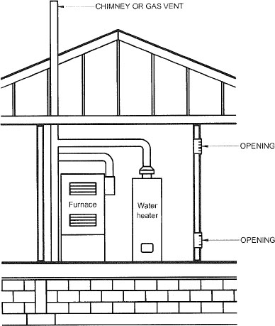
FIGURE 304.5.3
ALL AIR FROM INSIDE THE BUILDING (see Section 304.5.3)
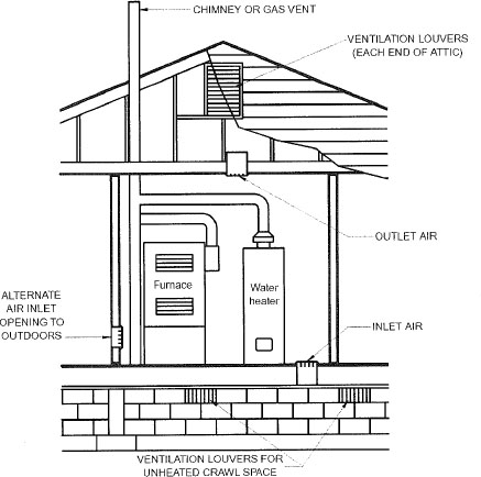
FIGURE 304.6.1(1)
ALL AIR FROM OUTDOORS—INLET AIR FROM VENTILATED CRAWL SPACE AND OUTLET AIR TO VENTILATED ATTIC (see Section 304.6.1)
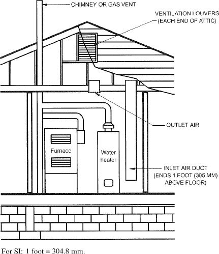
FIGURE 304.6.1(2)
ALL AIR FROM OUTDOORS THROUGH VENTILATED ATTIC (see Section 304.6.1)
304.6.2 One-permanent-opening method. One permanent opening, commencing within 12 inches (305 mm) of the top of the enclosure, shall be provided. The appliance shall have clearances of at least 1 inch (25 mm) from the sides and back and 6 inches (152 mm) from the front of the appliance. The opening shall directly communicate with the outdoors or through a vertical or horizontal duct to the outdoors, or spaces that freely communicate with the outdoors (see Figure 304.6.2) and shall have a minimum free area of 1 square inch per 3,000 Btu/h (734 mm2/kW) of the total input rating of all appliances located in the enclosure and not less than the sum of the areas of all vent connectors in the space.
304.7 Combination indoor and outdoor combustion air. The use of a combination of indoor and outdoor combustion air shall be in accordance with Sections 304.7.1 through 304.7.3.
304.7.1 Indoor openings. Where used, openings connecting the interior spaces shall comply with Section 304.5.3.
304.7.2 Outdoor opening location. Outdoor opening(s) shall be located in accordance with Section 304.6.
304.7.3 Outdoor opening(s) size. The outdoor opening(s) size shall be calculated in accordance with the following:
- The ratio of interior spaces shall be the available volume of all communicating spaces divided by the required volume.
- The outdoor size reduction factor shall be one minus the ratio of interior spaces.
- The minimum size of outdoor opening(s) shall be the full size of outdoor opening(s) calculated in accordance with Section 304.6, multiplied by the reduction factor. The minimum dimension of air openings shall be not less than 3 inches (76 mm).
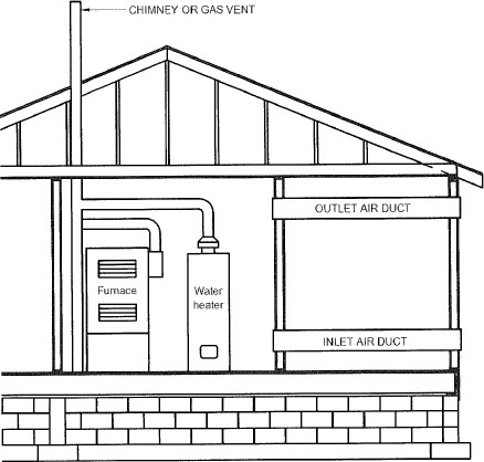
FIGURE 304.6.1(3)
ALL AIR FROM OUTDOORS (see Section 304.6.1)
304.8 Engineered installations. Engineered combustion air installations shall provide an adequate supply of combustion, ventilation and dilution air and shall be approved.
304.9 Mechanical combustion air supply. Where all combustion air is provided by a mechanical air supply system, the combustion air shall be supplied from the outdoors at a rate not less than 0.35 cubic feet per minute per 1,000 Btu/h (0.034 m3/min per kW) of total input rating of all appliances located within the space.
304.9.1 Makeup air. Where exhaust fans are installed, makeup air shall be provided to replace the exhausted air.
304.9.2 Appliance interlock. Each of the appliances served shall be interlocked with the mechanical air supply system to prevent main burner operation when the mechanical air supply system is not in operation.
304.9.3 Combined combustion air and ventilation air system. Where combustion air is provided by the building’s mechanical ventilation system, the system shall provide the specified combustion air rate in addition to the required ventilation air.
304.10 Louvers and grilles. The required size of openings for combustion, ventilation and dilution air shall be based on the net free area of each opening. Where the free area through a design of louver, grille or screen is known, it shall be used in calculating the size opening required to provide the free area specified. Where the design and free area of louvers and grilles are not known, it shall be assumed that wood louvers will have 25-percent free area and metal louvers and grilles will have 75-percent free area. Screens shall have a mesh size not smaller than ¼ inch (6.4 mm). Nonmotorized louvers and grilles shall be fixed in the open position. Motorized louvers
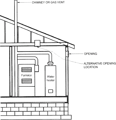
FIGURE 304.6.2
SINGLE COMBUSTION AIR OPENING, ALL AIR FROM THE OUTDOORS (see Section 304.6.2)
shall be interlocked with the appliance so that they are proven to be in the full open position prior to main burner ignition and during main burner operation. Means shall be provided to prevent the main burner from igniting if the louvers fail to open during burner start-up and to shut down the main burner if the louvers close during operation.
304.11 Combustion air ducts. Combustion air ducts shall comply with all of the following:
Exception: Within dwellings units, unobstructed stud and joist spaces shall not be prohibited from conveying combustion air, provided that not more than one required fireblock is removed.
Exception: Direct-vent gas-fired appliances designed for installation in a solid fuel-burning fireplace where installed in accordance with the manufacturer’s instructions.
304.12 Protection from fumes and gases. Where corrosive or flammable process fumes or gases, other than products of combustion, are present, means for the disposal of such fumes or gases shall be provided. Such fumes or gases include carbon monoxide, hydrogen sulfide, ammonia, chlorine and halogenated hydrocarbons.
In barbershops, beauty shops and other facilities where chemicals that generate corrosive or flammable products, such as aerosol sprays, are routinely used, nondirect vent-type appliances shall be located in a mechanical room separated or partitioned off from other areas with provisions for combustion air and dilution air from the outdoors. Direct-vent appliances shall be installed in accordance with the appliance manufacturer’s installation instructions.
305.1 General. Equipment and appliances shall be installed as required by the terms of their approval, in accordance with the conditions of listing, the manufacturer’s instructions and this code. Manufacturers’ installation instructions shall be available on the job site at the time of inspection. Where a code provision is less restrictive than the conditions of the listing of the equipment or appliance or the manufacturer’s installation instructions, the conditions of the listing and the manufacturer’s installation instructions shall apply.
Unlisted appliances approved in accordance with Section 301.3 shall be limited to uses recommended by the manufacturer and shall be installed in accordance with the manufacturer’s instructions, the provisions of this code and the requirements determined by the code official.
305.2 Hazardous area. Equipment and appliances having an ignition source shall not be installed in Group H occupancies or control areas where open use, handling or dispensing of combustible, flammable or explosive materials occurs.
305.3 Elevation of ignition source. Equipment and appliances having an ignition source shall be elevated such that the source of ignition is not less than 18 inches (457 mm) above the floor in hazardous locations and public garages, private garages, repair garages, motor fuel-dispensing facilities and parking garages. For the purpose of this section, rooms or spaces that are not part of the living space of a dwelling unit and that communicate directly with a private garage through openings shall be considered to be part of the private garage.
Exception: Elevation of the ignition source is not required for appliances that are listed as flammable vapor ignition resistant.
305.3.1 (IFGS) Installation in residential garages. In residential garages where appliances are installed in a separate, enclosed space having access only from outside of the garage, such appliances shall be permitted to be installed at floor level, provided that the required combustion air is taken from the exterior of the garage.
305.3.2 Parking garages. Connection of a parking garage with any room in which there is a fuel-fired appliance shall be by means of a vestibule providing a two-doorway separation, except that a single door is permitted where the sources of ignition in the appliance are elevated in accordance with Section 305.3.
Exception: This section shall not apply to appliance installations complying with Section 305.4.
305.4 Public garages. Appliances located in public garages, motor fuel-dispensing facilities, repair garages or other areas frequented by motor vehicles shall be installed a minimum of 8 feet (2438 mm) above the floor. Where motor vehicles are capable of passing under an appliance, the appliance shall be installed at the clearances required by the appliance manufacturer and not less than 1 foot (305 mm) higher than the tallest vehicle garage door opening.
22Exception: The requirements of this section shall not apply where the appliances are protected from motor vehicle
impact and installed in accordance with Section 305.3 and NFPA 30A.
305.5 Private garages. Appliances located in private garages shall be installed with a minimum clearance of 6 feet (1829 mm) above the floor.
Exception: The requirements of this section shall not apply where the appliances are protected from motor vehicle impact and installed in accordance with Section 305.3.
305.6 Construction and protection. Boiler rooms and furnace rooms shall be protected as required by the International Building Code.
305.7 Clearances from grade. Equipment and appliances installed at grade level shall be supported on a level concrete slab or other approved material extending not less than 3-inches (76 mm) above adjoining grade or shall be suspended not less than 6 inches (152 mm) above adjoining grade. Such supports shall be installed in accordance with the manufacturer’s installation instructions.
305.8 Clearances to combustible construction. Heat-producing equipment and appliances shall be installed to maintain the required clearances to combustible construction as specified in the listing and manufacturer’s instructions. Such clearances shall be reduced only in accordance with Section 308. Clearances to combustibles shall include such considerations as door swing, drawer pull, overhead projections or shelving and window swing. Devices, such as door stops or limits and closers, shall not be used to provide the required clearances.
305.9 (IFGS) Parking structures. Appliances installed in enclosed, basement and underground parking structures shall be installed in accordance with NFPA 88A.
305.10 (IFGS) Repair garages. Appliances installed in repair garages shall be installed in a detached building or room, separated from repair areas by walls or partitions, floors or floor-ceiling assemblies that are constructed so as to prohibit the transmission of vapors and having a fire-resistance rating of not less than 1 hour, and that have no openings in the wall separating the repair area within 8 feet (2438 mm) of the floor. Wall penetrations shall be firestopped. Air for combustion purposes shall be obtained from the outdoors. The appliance room shall not be used for the storage of combustible materials.
Exceptions:
- Overhead heaters where installed not less than 8 feet (2438 mm) above the floor shall be permitted.
- Heating appliances for vehicle repair areas where there is no dispensing or transferring of Class I or II flammable or combustible liquids or liquefied petroleum gas shall be installed in accordance with NFPA 30A.
305.11 (IFGS) Installation in aircraft hangars. Heaters in aircraft hangars shall be installed in accordance with NFPA 409.
305.12 (IFGS) Avoid strain on gas piping. Appliances shall be supported and connected to the piping so as not to exert undue strain on the connections.
[M] 306.1 Access for maintenance and replacement. Appliances shall be accessible for inspection, service, repair and replacement without disabling the function of a fire-resistance-rated assembly or removing permanent construction, other appliances, or any other piping or ducts not connected to the appliance being inspected, serviced, repaired or replaced. A level working space at least 30 inches deep and 30 inches wide (762 mm by 762 mm) shall be provided in front of the control side to service an appliance.
[M] 306.2 Appliances in rooms. Rooms containing appliances shall be provided with a door and an unobstructed passageway measuring not less than 36 inches (914 mm) wide and 80 inches (2032 mm) high.
Exception: Within a dwelling unit, appliances installed in a compartment, alcove, basement or similar space shall be provided with access by an opening or door and an unobstructed passageway measuring not less than 24 inches (610 mm) wide and large enough to allow removal of the largest appliance in the space, provided that a level service space of not less than 30 inches (762 mm) deep and the height of the appliance, but not less than 30 inches (762 mm), is present at the front or service side of the appliance with the door open.
[M] 306.3 Appliances in attics. Attics containing appliances shall be provided with an opening and unobstructed passageway large enough to allow removal of the largest appliance. The passageway shall not be less than 30 inches (762 mm) high and 22 inches (559 mm) wide and not more than 20 feet (6096 mm) in length measured along the centerline of the passageway from the opening to the appliance. The passageway shall have continuous solid flooring not less than 24 inches (610 mm) wide. A level service space not less than 30 inches (762 mm) deep and 30 inches (762 mm) wide shall be present at the front or service side of the appliance. The clear access opening dimensions shall be a minimum of 20 inches by 30 inches (508 mm by 762 mm), and large enough to allow removal of the largest appliance.
Exceptions:
- The passageway and level service space are not required where the appliance is capable of being serviced and removed through the required opening.
- Where the passageway is not less than 6 feet (1829 mm) high for its entire length, the passageway shall be not greater than 50 feet (15 250 mm) in length.
[M] 306.3.1 Electrical requirements. A luminaire controlled by a switch located at the required passageway opening and a receptacle outlet shall be provided at or near the appliance location in accordance with NFPA 70.
[M] 306.4 Appliances under floors. Under-floor spaces containing appliances shall be provided with an access opening and unobstructed passageway large enough to remove the largest appliance. The passageway shall not be less than 30 inches (762 mm) high and 22 inches (559 mm) wide, nor more than 20 feet (6096 mm) in length measured along the centerline of the passageway from the opening to the appliance.
23A level service space not less than 30 inches (762 mm) deep and 30 inches (762 mm) wide shall be present at the front or service side of the appliance. If the depth of the passageway or the service space exceeds 12 inches (305 mm) below the adjoining grade, the walls of the passageway shall be lined with concrete or masonry extending 4 inches (102 mm) above the adjoining grade and having sufficient lateral-bearing capacity to resist collapse. The clear access opening dimensions shall be a minimum of 22 inches by 30 inches (559 mm by 762 mm), and large enough to allow removal of the largest appliance.
Exceptions:
- The passageway is not required where the level service space is present when the access is open and the appliance is capable of being serviced and removed through the required opening.
- Where the passageway is not less than 6 feet high (1829 mm) for its entire length, the passageway shall not be limited in length.
[M] 306.4.1 Electrical requirements. A luminaire controlled by a switch located at the required passageway opening and a receptacle outlet shall be provided at or near the appliance location in accordance with NFPA 70.
[M] 306.5 Equipment and appliances on roofs or elevated structures. Where equipment requiring access or appliances are located on an elevated structure or the roof of a building such that personnel will have to climb higher than 16 feet (4877 mm) above grade to access such equipment or appliances, an interior or exterior means of access shall be provided. Such access shall not require climbing over obstructions greater than 30 inches (762 mm) in height or walking on roofs having a slope greater than 4 units vertical in 12 units horizontal (33-percent slope). Such access shall not require the use of portable ladders.
Permanent ladders installed to provide the required access shall comply with the following minimum design criteria:
Catwalks installed to provide the required access shall be not less than 24 inches (610 mm) wide and shall have railings as required for service platforms.
Exception: This section shall not apply to Group R-3 occupancies.
[M] 306.5.1 Sloped roofs. Where appliances, equipment, fans or other components that require service are installed on a roof having a slope of 3 units vertical in 12 units horizontal (25-percent slope) or greater and having an edge more than 30 inches (762 mm) above grade at such edge, a level platform shall be provided on each side of the appliance or equipment to which access is required for service, repair or maintenance. The platform shall be not less than 30 inches (762 mm) in any dimension and shall be provided with guards. The guards shall extend not less than 42 inches (1067 mm) above the platform, shall be constructed so as to prevent the passage of a 21-inch-diameter (533 mm) sphere and shall comply with the loading requirements for guards specified in the International Building Code. Access shall not require walking on roofs having a slope greater than 4 units vertical in 12 units horizontal (33-percent slope). Where access involves obstructions greater than 30 inches (762 mm) in height, such obstructions shall be provided with ladders installed in accordance with Section 306.5 or stairs installed in accordance with the requirements specified in the International Building Code in the path of travel to and from appliances, fans or equipment requiring service.
[M] 306.5.2 Electrical requirements. A receptacle outlet shall be provided at or near the appliance location in accordance with NFPA 70.
[M] 306.6 Guards. Guards shall be provided where appliances or other components that require service and roof hatch openings are located within 10 feet (3048 mm) of a roof edge or open side of a walking surface and such edge or open side is located more than 30 inches (762 mm) above the floor, roof or grade below. The guard shall extend not less than 30 inches (762 mm) beyond each end of such appliances, components and roof hatch openings and the top of the guard
24shall be located not less than 42 inches (1067 mm) above the elevated surface adjacent to the guard. The guard shall be constructed so as to prevent the passage of a 21-inch-diameter (533 mm) sphere and shall comply with the loading requirements for guards specified in the International Building Code.
307.1 Evaporators and cooling coils. Condensate drainage systems shall be provided for equipment and appliances containing evaporators and cooling coils in accordance with the International Mechanical Code.
307.2 Fuel-burning appliances. Liquid combustion byproducts of condensing appliances shall be collected and discharged to an approved plumbing fixture or disposal area in accordance with the manufacturer’s installation instructions. Condensate piping shall be of approved corrosion-resistant material and shall not be smaller than the drain connection on the appliance. Such piping shall maintain a minimum slope in the direction of discharge of not less than one-eighth unit vertical in 12 units horizontal (1-percent slope).
[M] 307.3 Drain pipe materials and sizes. Components of the condensate disposal system shall be cast iron, galvanized steel, copper, cross-linked polyethylene, polybutylene, polyethylene, ABS, CPVC or PVC pipe or tubing. All components shall be selected for the pressure and temperature rating of the installation. Joints and connections shall be made in accordance with the applicable provisions of Chapter 7 of the International Plumbing Code relative to the material type. Condensate waste and drain line size shall be not less than ¾-inch (19 mm) internal diameter and shall not decrease in size from the drain pan connection to the place of condensate disposal. Where the drain pipes from more than one unit are manifolded together for condensate drainage, the pipe or tubing shall be sized in accordance with an approved method.
307.4 Traps. Condensate drains shall be trapped as required by the equipment or appliance manufacturer.
307.5 Auxiliary drain pan. Category IV condensing appliances shall be provided with an auxiliary drain pan where damage to any building component will occur as a result of stoppage in the condensate drainage system. Such pan shall be installed in accordance with the applicable provisions of Section 307 of the International Mechanical Code.
Exception: An auxiliary drain pan shall not be required for appliances that automatically shut down operation in the event of a stoppage in the condensate drainage system.
308.1 Scope. This section shall govern the reduction in required clearances to combustible materials, including gypsum board, and combustible assemblies for chimneys, vents, appliances, devices and equipment. Clearance requirements for air-conditioning equipment and central heating boilers and furnaces shall comply with Sections 308.3 and 308.4.
308.2 Reduction table. The allowable clearance reduction shall be based on one of the methods specified in Table 308.2 or shall utilize an assembly listed for such application. Where required clearances are not listed in Table 308.2, the reduced clearances shall be determined by linear interpolation between the distances listed in the table. Reduced clearances shall not be derived by extrapolation below the range of the table. The reduction of the required clearances to combustibles for listed and labeled appliances and equipment shall be in accordance with the requirements of this section except that such clearances shall not be reduced where reduction is specifically prohibited by the terms of the appliance or equipment listing [see Figures 308.2(1) through 308.2(3)].
308.3 Clearances for indoor air-conditioning appliances. Clearance requirements for indoor air-conditioning appliances shall comply with Sections 308.3.1 through 308.3.4.
308.3.1 Appliance clearances. Air-conditioning appliances shall be installed with clearances in accordance with the manufacturer’s instructions.
308.3.2 Clearance reduction. Air-conditioning appliances shall be permitted to be installed with reduced clearances to combustible material, provided that the combustible material or appliance is protected as described in Table 308.2 and such reduction is allowed by the manufacturer’s instructions.
308.3.3 Plenum clearances. Where the furnace plenum is adjacent to plaster on metal lath or noncombustible material attached to combustible material, the clearance shall be measured to the surface of the plaster or other noncombustible finish where the clearance specified is 2 inches (51 mm) or less.
308.3.4 Clearance from supply ducts. Supply air ducts connecting to listed central heating furnaces shall have the same minimum clearance to combustibles as required for the furnace supply plenum for a distance of not less than 3 feet (914 mm) from the supply plenum. Clearance is not required beyond the 3-foot (914 mm) distance.
308.4 Central-heating boilers and furnaces. Clearance requirements for central-heating boilers and furnaces shall comply with Sections 308.4.1 through 308.4.5. The clearance to these appliances shall not interfere with combustion air; draft hood clearance and relief; and accessibility for servicing.
25308.4.1 Appliance clearances. Central-heating furnaces and low-pressure boilers shall be installed with clearances in accordance with the manufacturer’s instructions.
308.4.2 Clearance reduction. Central-heating furnaces and low-pressure boilers shall be permitted to be installed with reduced clearances to combustible material provided that the combustible material or appliance is protected as described in Table 308.2 and such reduction is allowed by the manufacturer’s instructions.
308.4.3 Clearance for servicing appliances. Front clearance shall be sufficient for servicing the burner and the furnace or boiler.
308.4.4 Plenum clearances. Where the furnace plenum is adjacent to plaster on metal lath or noncombustible material
attached to combustible material, the clearance shall be measured to the surface of the plaster or other noncombustible finish where the clearance specified is 2 inches (51 mm) or less.
308.4.5 Clearance from supply ducts. Supply air ducts connecting to listed central heating furnaces shall have the same minimum clearance to combustibles as required for the furnace supply plenum for a distance of not less than 3 feet (914 mm) from the supply plenum. Clearance is not required beyond the 3-foot (914 mm) distance.
| TYPE OF PROTECTION APPLIED TO AND COVERING ALL SURFACES OF COMBUSTIBLE MATERIAL WITHIN THE DISTANCE SPECIFIED AS THE REQUIRED CLEARANCE WITH NO PROTECTION [see Figures 308.2(1), 308.2(2), and 308.2(3)] | WHERE THE REQUIRED CLEARANCE WITH NO PROTECTION FROM APPLIANCE, VENT CONNECTOR, OR SINGLE-WALL METAL PIPE IS: (inches) | |||||||||
|---|---|---|---|---|---|---|---|---|---|---|
| 36 | 18 | 12 | 9 | 6 | ||||||
| Allowable clearances with specified protection (inches) | ||||||||||
| Use Column 1 for clearances above appliance or horizontal connector. Use Column 2 for clearances from appliance, vertical connector and single-wall metal pipe. | ||||||||||
| Above Col. 1 | Sides and rear Col. 2 | Above Col. 1 | Sides and rear Col. 2 | Above Col. 1 | Sides and rear Col. 2 | Above Col. 1 | Sides and rear Col. 2 | Above Col. 1 | Sides and rear Col. 2 | |
| 1. 3½-inch-thick masonry wall without ventilated airspace | — | 24 | — | 12 | — | 9 | — | 6 | — | 5 |
| 2. ½-inch insulation board over 1-inch glass fiber or mineral wool batts | 24 | 18 | 12 | 9 | 9 | 6 | 6 | 5 | 4 | 3 |
| 3. 0.024-inch (nominal 24 gage) sheet metal over 1-inch glass fiber or mineral wool batts reinforced with wire on rear face with ventilated airspace | 18 | 12 | 9 | 6 | 6 | 4 | 5 | 3 | 3 | 3 |
| 4. 3½-inch-thick masonry wall with ventilated airspace | — | 12 | — | 6 | — | 6 | — | 6 | — | 6 |
| 5. 0.024-inch (nominal 24 gage) sheet metal with ventilated airspace | 18 | 12 | 9 | 6 | 6 | 4 | 5 | 3 | 3 | 2 |
| 6. ½-inch-thick insulation board with ventilated airspace | 18 | 12 | 9 | 6 | 6 | 4 | 5 | 3 | 3 | 3 |
| 7. 0.024-inch (nominal 24 gage) sheet metal with ventilated airspace over 0.024-inch (nominal 24 gage) sheet metal with ventilated airspace | 18 | 12 | 9 | 6 | 6 | 4 | 5 | 3 | 3 | 3 |
| 8. 1-inch glass fiber or mineral wool batts sandwiched between two sheets 0.024-inch (nominal 24 gage) sheet metal with ventilated airspace | 18 | 12 | 9 | 6 | 6 | 4 | 5 | 3 | 3 | 3 |
For SI: 1 inch = 25.4 mm, °C = [(°F − 32)/l .8], 1 pound per cubic foot = 16.02 kg/m3, 1 Btu per inch per square foot per hour per °F = 0.144 W/m2 · K.
|
||||||||||
309.1 Grounding. Gas piping shall not be used as a grounding electrode.
309.2 Connections. Electrical connections between appliances and the building wiring, including the grounding of the appliances, shall conform to NFPA 70.
26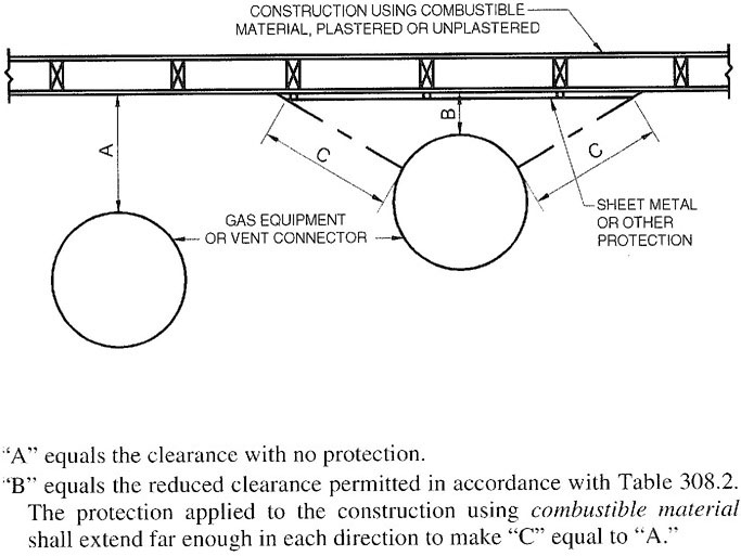
FIGURE 308.2(1)
EXTENT OF PROTECTION NECESSARY TO REDUCE CLEARANCES FROM APPLIANCE FOR VENT CONNECTIONS
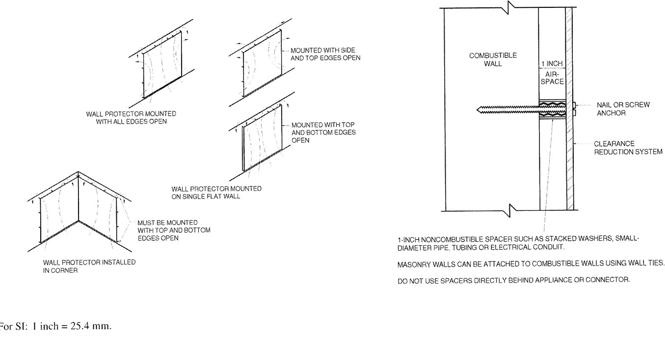
FIGURE 308.2(2)
WALL PROTECTOR CLEARANCE REDUCTION SYSTEM
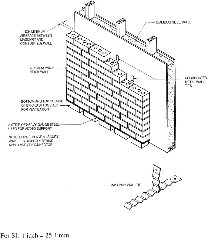
FIGURE 308.2(3)
MASONRY CLEARANCE REDUCTION SYSTEM
310.1 Pipe and tubing other than CSST. Each above-ground portion of a gas piping system other than corrugated stainless steel tubing (CSST) that is likely to become energized shall be electrically continuous and bonded to an effective ground-fault current path. Gas piping other than CSST shall be considered to be bonded where it is connected to appliances that are connected to the equipment grounding conductor of the circuit supplying that appliance.
28310.1.1 CSST. Corrugated stainless steel tubing (CSST) gas piping systems shall be bonded to the electrical service grounding electrode system. The bonding jumper shall connect to a metallic pipe or fitting between the point of delivery and the first downstream CSST fitting. The bonding jumper shall be not smaller than 6 AWG copper wire or equivalent. Gas piping systems that contain one or more segments of CSST shall be bonded in accordance with this section.
401.1 Scope. This chapter shall govern the design, installation, modification and maintenance of piping systems. The applicability of this code to piping systems extends from the point of delivery to the connections with the appliances and includes the design, materials, components, fabrication, assembly, installation, testing, inspection, operation and maintenance of such piping systems.
401.1.1 Utility piping systems located within buildings. Utility service piping located within buildings shall be installed in accordance with the structural safety and fire protection provisions of the International Building Code.
401.2 Liquefied petroleum gas storage. The storage system for liquefied petroleum gas shall be designed and installed in accordance with the International Fire Code and NFPA 58.
401.3 Modifications to existing systems. In modifying or adding to existing piping systems, sizes shall be maintained in accordance with this chapter.
401.4 Additional appliances. Where an additional appliance is to be served, the existing piping shall be checked to determine if it has adequate capacity for all appliances served. If inadequate, the existing system shall be enlarged as required or separate piping of adequate capacity shall be provided.
401.5 Identification. For other than steel pipe, exposed piping shall be identified by a yellow label marked “Gas” in black letters. The marking shall be spaced at intervals not exceeding 5 feet (1524 mm). The marking shall not be required on pipe located in the same room as the appliance served.
401.6 Interconnections. Where two or more meters are installed on the same premises but supply separate consumers, the piping systems shall not be interconnected on the outlet side of the meters.
401.7 Piping meter identification. Piping from multiple meter installations shall be marked with an approved permanent identification by the installer so that the piping system supplied by each meter is readily identifiable.
401.8 Minimum sizes. All pipe utilized for the installation, extension and alteration of any piping system shall be sized to supply the full number of outlets for the intended purpose and shall be sized in accordance with Section 402.
401.9 Identification. Each length of pipe and tubing and each pipe fitting, utilized in a fuel gas system, shall bear the identification of the manufacturer.
401.10 Third-party testing and certification. All piping, tubing and fittings shall comply with the applicable referenced standards, specifications and performance criteria of this code and shall be identified in accordance with Section 401.9. Piping, tubing and fittings shall either be tested by an approved third-party testing agency or certified by an approved third-party certification agency.
402.1 General considerations. Piping systems shall be of such size and so installed as to provide a supply of gas sufficient to meet the maximum demand and supply gas to each appliance inlet at not less than the minimum supply pressure required by the appliance.
402.2 Maximum gas demand. The volumetric flow rate of gas to be provided, in cubic feet per hour, shall be calculated using the manufacturer’s input ratings of the appliances served adjusted for altitude. Where an input rating is not indicated, the gas supplier, appliance manufacturer or a qualified agency shall be contacted, or the rating from Table 402.2 shall be used for estimating the volumetric flow rate of gas to be supplied.
The total connected hourly load shall be used as the basis for pipe sizing, assuming that all appliances could be operating at full capacity simultaneously. Where a diversity of load can be established, pipe sizing shall be permitted to be based on such loads.
402.3 Sizing. Gas piping shall be sized in accordance with one of the following:
402.4 Sizing tables and equations. Where Tables 402.4(1) through 402.4(35) are used to size piping or tubing, the pipe length shall be determined in accordance with Section 402.4.1, 402.4.2 or 402.4.3.
Where Equations 4-1 and 4-2 are used to size piping or tubing, the pipe or tubing shall have smooth inside walls and the pipe length shall be determined in accordance with Section 402.4.1, 402.4.2 or 402.4.3.
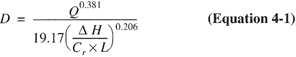
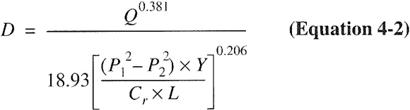
where:
D = Inside diameter of pipe, inches (mm).
Q = Input rate appliance(s), cubic feet per hour at 60°F (16°C) and 30-inch mercury column.
P1 = Upstream pressure, psia (P1 + 14.7).
P2 = Downstream pressure, psia (P2 + 14.7).
L = Equivalent length of pipe, feet.
ΔH = Pressure drop, inch water column (27.7 inch water column = 1 psi).
| GAS | EQUATION FACTORS | |
|---|---|---|
| Cr | Y | |
| Natural gas | 0.6094 | 0.9992 |
| Undiluted propane | 1.2462 | 0.9910 |
| For SI: 1 cubic foot = 0.028 m3, 1 foot = 305 mm, 1-inch water column = 0.2488 kPa, 1 pound per square inch = 6.895 kPa, 1 British thermal unit per hour = 0.293 W. |
||
402.4.1 Longest length method. The pipe size of each section of gas piping shall be determined using the longest length of piping from the point of delivery to the most remote outlet and the load of the section.
402.4.2 Branch length method. Pipe shall be sized as follows:
- Pipe size of each section of the longest pipe run from the point of delivery to the most remote outlet shall be determined using the longest run of piping and the load of the section.
- The pipe size of each section of branch piping not previously sized shall be determined using the length of piping from the point of delivery to the most remote outlet in each branch and the load of the section.
402.4.3 Hybrid pressure. The pipe size for each section of higher pressure gas piping shall be determined using the longest length of piping from the point of delivery to the most remote line pressure regulator. The pipe size from the line pressure regulator to each outlet shall be determined using the length of piping from the regulator to the most remote outlet served by the regulator.
| APPLIANCE | INPUT BTU/H (Approx.) |
|---|---|
| Space Heating Units | |
| Hydronic boiler | |
| Single family | 100,000 |
| Multifamily, per unit | 60,000 |
| Warm-air furnace | |
| Single family | 100,000 |
| Multifamily, per unit | 60,000 |
| Space and Water Heating Units | |
| Hydronic boiler | |
| Single family | 120,000 |
| Multifamily, per unit | 75,000 |
| Water Heating Appliances | |
| Water heater, automatic instantaneous | |
| Capacity at 2 gal./minute | 142,800 |
| Capacity at 4 gal./minute | 285,000 |
| Capacity at 6 gal./minute | 428,400 |
| Water heater, automatic storage, 30- to 40-gal, tank | 35,000 |
| Water heater, automatic storage, 50-gal, tank | 50,000 |
| Water heater, domestic, circulating or side-arm | 35,000 |
| Cooking Appliances | |
| Built-in oven or broiler unit, domestic | 25,000 |
| Built-in top unit, domestic | 40,000 |
| Range, free-standing, domestic | 65,000 |
| Other Appliances | |
| Barbecue | 40,000 |
| Clothes dryer, Type 1 (domestic) | 35,000 |
| Gas fireplace, direct-vent | 40,000 |
| Gas light | 2,500 |
| Gas log | 80,000 |
| Refrigerator | 3,000 |
| For SI: 1 British thermal unit per hour = 0.293 W, 1 gallon = 3.785 L, 1 gallon per minute = 3.785 L/m. |
|
402.5 Allowable pressure drop. The design pressure loss in any piping system under maximum probable flow conditions, from the point of delivery to the inlet connection of the appliance, shall be such that the supply pressure at the appliance is greater than or equal to the minimum pressure required by the appliance.
30| Gas | Natural | |||||||||||||
|---|---|---|---|---|---|---|---|---|---|---|---|---|---|---|
| Inlet Pressure | Less than 2 psi | |||||||||||||
| Pressure Drop | 0.3 in. w.c. | |||||||||||||
| Specific Gravity | 0.60 | |||||||||||||
| PIPE SIZE (inch) | ||||||||||||||
| Nominal | ½ | ¾ | 1 | 1¼ | 1½ | 2 | 2½ | 3 | 4 | 5 | 6 | 8 | 10 | 12 |
| Actual ID | 0.622 | 0.824 | 1.049 | 1.380 | 1.610 | 2.067 | 2.469 | 3.068 | 4.026 | 5.047 | 6.065 | 7.981 | 10.020 | 11.938 |
| Length (ft) | Capacity in Cubic Feet of Gas Per Hour | |||||||||||||
| 10 | 131 | 273 | 514 | 1,060 | 1,580 | 3,050 | 4,860 | 8,580 | 17,500 | 31,700 | 51,300 | 105,000 | 191,000 | 303,000 |
| 20 | 90 | 188 | 353 | 726 | 1,090 | 2,090 | 3,340 | 5,900 | 12,000 | 21,800 | 35,300 | 72,400 | 132,000 | 208,000 |
| 30 | 72 | 151 | 284 | 583 | 873 | 1,680 | 2,680 | 4,740 | 9,660 | 17,500 | 28,300 | 58,200 | 106,000 | 167,000 |
| 40 | 62 | 129 | 243 | 499 | 747 | 1,440 | 2,290 | 4,050 | 8,270 | 15,000 | 24,200 | 49,800 | 90,400 | 143,000 |
| 50 | 55 | 114 | 215 | 442 | 662 | 1,280 | 2,030 | 3,590 | 7,330 | 13,300 | 21,500 | 44,100 | 80,100 | 127,000 |
| 60 | 50 | 104 | 195 | 400 | 600 | 1,160 | 1,840 | 3,260 | 6,640 | 12,000 | 19,500 | 40,000 | 72,600 | 115,000 |
| 70 | 46 | 95 | 179 | 368 | 552 | 1,060 | 1,690 | 3,000 | 6,110 | 11,100 | 17,900 | 36,800 | 66,800 | 106,000 |
| 80 | 42 | 89 | 167 | 343 | 514 | 989 | 1,580 | 2,790 | 5,680 | 10,300 | 16,700 | 34,200 | 62,100 | 98,400 |
| 90 | 40 | 83 | 157 | 322 | 482 | 928 | 1,480 | 2,610 | 5,330 | 9,650 | 15,600 | 32,100 | 58,300 | 92,300 |
| 100 | 38 | 79 | 148 | 304 | 455 | 877 | 1,400 | 2,470 | 5,040 | 9,110 | 14,800 | 30,300 | 55,100 | 87,200 |
| 125 | 33 | 70 | 131 | 269 | 403 | 777 | 1,240 | 2,190 | 4,460 | 8,080 | 13,100 | 26,900 | 48,800 | 77,300 |
| 150 | 30 | 63 | 119 | 244 | 366 | 704 | 1,120 | 1,980 | 4,050 | 7,320 | 11,900 | 24,300 | 44,200 | 70,000 |
| 175 | 28 | 58 | 109 | 224 | 336 | 648 | 1,030 | 1,820 | 3,720 | 6,730 | 10,900 | 22,400 | 40,700 | 64,400 |
| 200 | 26 | 54 | 102 | 209 | 313 | 602 | 960 | 1,700 | 3,460 | 6,260 | 10,100 | 20,800 | 37,900 | 59,900 |
| 250 | 23 | 48 | 90 | 185 | 277 | 534 | 851 | 1,500 | 3,070 | 5,550 | 8,990 | 18,500 | 33,500 | 53,100 |
| 300 | 21 | 43 | 82 | 168 | 251 | 484 | 771 | 1,360 | 2,780 | 5,030 | 8,150 | 16,700 | 30,400 | 48,100 |
| 350 | 19 | 40 | 75 | 154 | 231 | 445 | 709 | 1,250 | 2,560 | 4,630 | 7,490 | 15,400 | 28,000 | 44,300 |
| 400 | 18 | 37 | 70 | 143 | 215 | 414 | 660 | 1,170 | 2,380 | 4,310 | 6,970 | 14,300 | 26,000 | 41,200 |
| 450 | 17 | 35 | 66 | 135 | 202 | 389 | 619 | 1,090 | 2,230 | 4,040 | 6,540 | 13,400 | 24,400 | 38,600 |
| 500 | 16 | 33 | 62 | 127 | 191 | 367 | 585 | 1,030 | 2,110 | 3,820 | 6,180 | 12,700 | 23,100 | 36,500 |
| 550 | 15 | 31 | 59 | 121 | 181 | 349 | 556 | 982 | 2,000 | 3,620 | 5,870 | 12,100 | 21,900 | 34,700 |
| 600 | 14 | 30 | 56 | 115 | 173 | 333 | 530 | 937 | 1,910 | 3,460 | 5,600 | 11,500 | 20,900 | 33,100 |
| 650 | 14 | 29 | 54 | 110 | 165 | 318 | 508 | 897 | 1,830 | 3,310 | 5,360 | 11,000 | 20,000 | 31,700 |
| 700 | 13 | 27 | 52 | 106 | 159 | 306 | 488 | 862 | 1,760 | 3,180 | 5,150 | 10,600 | 19,200 | 30,400 |
| 750 | 13 | 26 | 50 | 102 | 153 | 295 | 470 | 830 | 1,690 | 3,060 | 4,960 | 10,200 | 18,500 | 29,300 |
| 800 | 12 | 26 | 48 | 99 | 148 | 285 | 454 | 802 | 1,640 | 2,960 | 4,790 | 9,840 | 17,900 | 28,300 |
| 850 | 12 | 25 | 46 | 95 | 143 | 275 | 439 | 776 | 1,580 | 2,860 | 4,640 | 9,530 | 17,300 | 27,400 |
| 900 | 11 | 24 | 45 | 93 | 139 | 267 | 426 | 752 | 1,530 | 2,780 | 4,500 | 9,240 | 16,800 | 26,600 |
| 950 | 11 | 23 | 44 | 90 | 135 | 259 | 413 | 731 | 1,490 | 2,700 | 4,370 | 8,970 | 16,300 | 25,800 |
| 1,000 | 11 | 23 | 43 | 87 | 131 | 252 | 402 | 711 | 1,450 | 2,620 | 4,250 | 8,720 | 15,800 | 25,100 |
| 1,100 | 10 | 21 | 40 | 83 | 124 | 240 | 382 | 675 | 1,380 | 2,490 | 4,030 | 8,290 | 15,100 | 23,800 |
| 1,200 | NA | 20 | 39 | 79 | 119 | 229 | 364 | 644 | 1,310 | 2,380 | 3,850 | 7,910 | 14,400 | 22,700 |
| 1,300 | NA | 20 | 37 | 76 | 114 | 219 | 349 | 617 | 1,260 | 2,280 | 3,680 | 7,570 | 13,700 | 21,800 |
| 1,400 | NA | 19 | 35 | 73 | 109 | 210 | 335 | 592 | 1,210 | 2,190 | 3,540 | 7,270 | 13,200 | 20,900 |
| 1,500 | NA | 18 | 34 | 70 | 105 | 203 | 323 | 571 | 1,160 | 2,110 | 3,410 | 7,010 | 12,700 | 20,100 |
| 1,600 | NA | 18 | 33 | 68 | 102 | 196 | 312 | 551 | 1,120 | 2,030 | 3,290 | 6,770 | 12,300 | 19,500 |
| 1,700 | NA | 17 | 32 | 66 | 98 | 189 | 302 | 533 | 1,090 | 1,970 | 3,190 | 6,550 | 11,900 | 18,800 |
| 1,800 | NA | 16 | 31 | 64 | 95 | 184 | 293 | 517 | 1,050 | 1,910 | 3,090 | 6,350 | 11,500 | 18,300 |
| 1,900 | NA | 16 | 30 | 62 | 93 | 178 | 284 | 502 | 1,020 | 1,850 | 3,000 | 6,170 | 11,200 | 17,700 |
| 2,000 | NA | 16 | 29 | 60 | 90 | 173 | 276 | 488 | 1,000 | 1,800 | 2,920 | 6,000 | 10,900 | 17,200 |
| For SI: 1 inch = 25.4 mm, 1 foot = 304.8 mm, 1 pound per square inch = 6.895 kPa, 1-inch water column = 0.2488 kPa, 1 British thermal unit per hour = 0.2931 W, 1 cubic foot per hour = 0.0283 m3/h, 1 degree = 0.01745 rad. |
||||||||||||||
Notes:
|
||||||||||||||
| Gas | Natural | |||||||||||||
|---|---|---|---|---|---|---|---|---|---|---|---|---|---|---|
| Inlet Pressure | Less than 2 psi | |||||||||||||
| Pressure Drop | 0.5 in. w.c. | |||||||||||||
| Specific Gravity | 0.60 | |||||||||||||
| PIPE SIZE (inch) | ||||||||||||||
| Nominal | ½ | ¾ | 1 | 1¼ | 1½ | 2 | 2½ | 3 | 4 | 5 | 6 | 8 | 10 | 12 |
| Actual ID | 0.622 | 0.824 | 1.049 | 1.380 | 1.610 | 2.067 | 2.469 | 3.068 | 4.026 | 5.047 | 6.065 | 7.981 | 10.020 | 11.938 |
| Length (ft) | Capacity in Cubic Feet of Gas Per Hour | |||||||||||||
| 10 | 172 | 360 | 678 | 1,390 | 2,090 | 4,020 | 6,400 | 11,300 | 23,100 | 41,800 | 67,600 | 139,000 | 252,000 | 399,000 |
| 20 | 118 | 247 | 466 | 957 | l ,430 | 2,760 | 4,400 | 7,780 | 15,900 | 28,700 | 46,500 | 95,500 | 173,000 | 275,000 |
| 30 | 95 | 199 | 374 | 768 | 1,150 | 2,220 | 3,530 | 6,250 | 12,700 | 23,000 | 37,300 | 76,700 | 139,000 | 220,000 |
| 40 | 81 | 170 | 320 | 657 | 985 | 1,900 | 3,020 | 5,350 | 10,900 | 19,700 | 31,900 | 65,600 | 119,000 | 189,000 |
| 50 | 72 | 151 | 284 | 583 | 873 | 1,680 | 2,680 | 4,740 | 9,660 | 17,500 | 28,300 | 58,200 | 106,000 | 167,000 |
| 60 | 65 | 137 | 257 | 528 | 791 | 1,520 | 2,430 | 4,290 | 8,760 | 15,800 | 25,600 | 52,700 | 95,700 | 152,000 |
| 70 | 60 | 126 | 237 | 486 | 728 | 1,400 | 2,230 | 3,950 | 8,050 | 14,600 | 23,600 | 48,500 | 88,100 | 139,000 |
| 80 | 56 | 117 | 220 | 452 | 677 | 1,300 | 2,080 | 3,670 | 7,490 | 13,600 | 22,000 | 45,100 | 81,900 | 130,000 |
| 90 | 52 | 110 | 207 | 424 | 635 | 1,220 | 1,950 | 3,450 | 7,030 | 12,700 | 20,600 | 42,300 | 76,900 | 122,000 |
| 100 | 50 | 104 | 195 | 400 | 600 | 1,160 | 1,840 | 3,260 | 6,640 | 12,000 | 19,500 | 40,000 | 72,600 | 115,000 |
| 125 | 44 | 92 | 173 | 355 | 532 | 1,020 | 1,630 | 2,890 | 5,890 | 10,600 | 17,200 | 35,400 | 64,300 | 102,000 |
| 150 | 40 | 83 | 157 | 322 | 482 | 928 | 1,480 | 2,610 | 5,330 | 9,650 | 15,600 | 32,100 | 58,300 | 92,300 |
| 175 | 37 | 77 | 144 | 296 | 443 | 854 | 1,360 | 2,410 | 4,910 | 8,880 | 14,400 | 29,500 | 53,600 | 84,900 |
| 200 | 34 | 71 | 134 | 275 | 412 | 794 | 1,270 | 2,240 | 4,560 | 8,260 | 13,400 | 27,500 | 49,900 | 79,000 |
| 250 | 30 | 63 | 119 | 244 | 366 | 704 | 1,120 | 1,980 | 4,050 | 7,320 | 11,900 | 24,300 | 44,200 | 70,000 |
| 300 | 27 | 57 | 108 | 221 | 331 | 638 | 1,020 | 1,800 | 3,670 | 6,630 | 10,700 | 22,100 | 40,100 | 63,400 |
| 350 | 25 | 53 | 99 | 203 | 305 | 587 | 935 | 1,650 | 3,370 | 6,100 | 9,880 | 20,300 | 36,900 | 58,400 |
| 400 | 23 | 49 | 92 | 189 | 283 | 546 | 870 | 1,540 | 3,140 | 5,680 | 9,190 | 18,900 | 34,300 | 54,300 |
| 450 | 22 | 46 | 86 | 177 | 266 | 512 | 816 | 1,440 | 2,940 | 5,330 | 8,620 | 17,700 | 32,200 | 50,900 |
| 500 | 21 | 43 | 82 | 168 | 251 | 484 | 771 | 1,360 | 2,780 | 5,030 | 8,150 | 16,700 | 30,400 | 48,100 |
| 550 | 20 | 41 | 78 | 159 | 239 | 459 | 732 | 1,290 | 2,640 | 4,780 | 7,740 | 15,900 | 28,900 | 45,700 |
| 600 | 19 | 39 | 74 | 152 | 228 | 438 | 699 | 1,240 | 2,520 | 4,560 | 7,380 | 15,200 | 27,500 | 43,600 |
| 650 | 18 | 38 | 71 | 145 | 218 | 420 | 669 | 1,180 | 2,410 | 4,360 | 7,070 | 14,500 | 26,400 | 41,800 |
| 700 | 17 | 36 | 68 | 140 | 209 | 403 | 643 | 1,140 | 2,320 | 4,190 | 6,790 | 14,000 | 25,300 | 40,100 |
| 750 | 17 | 35 | 66 | 135 | 202 | 389 | 619 | 1,090 | 2,230 | 4,040 | 6,540 | 13,400 | 24,400 | 38,600 |
| 800 | 16 | 34 | 63 | 130 | 195 | 375 | 598 | 1,060 | 2,160 | 3,900 | 6,320 | 13,000 | 23,600 | 37,300 |
| 850 | 16 | 33 | 61 | 126 | 189 | 363 | 579 | 1,020 | 2,090 | 3,780 | 6,110 | 12,600 | 22,800 | 36,100 |
| 900 | 15 | 32 | 59 | 122 | 183 | 352 | 561 | 992 | 2,020 | 3,660 | 5,930 | 12,200 | 22,100 | 35,000 |
| 950 | 15 | 31 | 58 | 118 | 178 | 342 | 545 | 963 | 1,960 | 3,550 | 5,760 | 11,800 | 21,500 | 34,000 |
| 1,000 | 14 | 30 | 56 | 115 | 173 | 333 | 530 | 937 | 1,910 | 3,460 | 5,600 | 11,500 | 20,900 | 33,100 |
| 1,100 | 14 | 28 | 53 | 109 | 164 | 316 | 503 | 890 | 1,810 | 3,280 | 5,320 | 10,900 | 19,800 | 31,400 |
| 1,200 | 13 | 27 | 51 | 104 | 156 | 301 | 480 | 849 | 1,730 | 3,130 | 5,070 | 10,400 | 18,900 | 30,000 |
| 1,300 | 12 | 26 | 49 | 100 | 150 | 289 | 460 | 813 | 1,660 | 3,000 | 4,860 | 9,980 | 18,100 | 28,700 |
| 1,400 | 12 | 25 | 47 | 96 | 144 | 277 | 442 | 781 | 1,590 | 2,880 | 4,670 | 9,590 | 17,400 | 27,600 |
| 1,500 | 11 | 24 | 45 | 93 | 139 | 267 | 426 | 752 | 1,530 | 2,780 | 4,500 | 9,240 | 16,800 | 26,600 |
| 1,600 | 11 | 23 | 44 | 89 | 134 | 258 | 411 | 727 | 1,480 | 2,680 | 4,340 | 8,920 | 16,200 | 25,600 |
| 1,700 | 11 | 22 | 42 | 86 | 130 | 250 | 398 | 703 | 1,430 | 2,590 | 4,200 | 8,630 | 15,700 | 24,800 |
| 1,800 | 10 | 22 | 41 | 84 | 126 | 242 | 386 | 682 | 1,390 | 2,520 | 4,070 | 8,370 | 15,200 | 24,100 |
| 1,900 | 10 | 21 | 40 | 81 | 122 | 235 | 375 | 662 | 1,350 | 2,440 | 3,960 | 8,130 | 14,800 | 23,400 |
| 2,000 | NA | 20 | 39 | 79 | 119 | 229 | 364 | 644 | 1,310 | 2,380 | 3,850 | 7,910 | 14,400 | 22,700 |
| For SI: 1 inch = 25.4 mm, 1 foot = 304.8 mm. 1 pound per square inch = 6.895 kPa, 1-inch water column = 0.2488 kPa, 1 British thermal unit per hour = 0.2931 W, 1 cubic foot per hour = 0.0283 m3/h, 1 degree = 0.01745 rad. |
||||||||||||||
Notes:
|
||||||||||||||
| Gas | Natural | ||||||||
|---|---|---|---|---|---|---|---|---|---|
| Inlet Pressure | Less than 2 psi | ||||||||
| Pressure Drop | 3.0 in. w.c. | ||||||||
| Specific Gravity | 0.60 | ||||||||
| INTENDED USE: Initial supply pressure of 8.0 inches w.c. or greater | |||||||||
| PIPE SIZE (inch) | |||||||||
| Nominal | ½ | ¾ | 1 | 1¼ | 1½ | 2 | 2½ | 3 | 4 |
| Actual ID | 0.622 | 0.824 | 1.049 | 1.380 | 1.610 | 2.067 | 2.469 | 3.068 | 4.026 |
| Length (ft) | Capacity in Cubic Feet of Gas Per Hour | ||||||||
| 10 | 454 | 949 | 1,787 | 3,669 | 5,497 | 10,588 | 16,875 | 29,832 | 43,678 |
| 20 | 312 | 652 | 1,228 | 2,522 | 3,778 | 7,277 | 11,598 | 20,503 | 30,020 |
| 30 | 250 | 524 | 986 | 2,025 | 3,034 | 5,844 | 9,314 | 16,465 | 24,107 |
| 40 | 214 | 448 | 844 | 1,733 | 2,597 | 5,001 | 7,971 | 14,092 | 20,632 |
| 50 | 190 | 397 | 748 | 1,536 | 2,302 | 4,433 | 7,065 | 12,489 | 18,286 |
| 60 | 172 | 360 | 678 | 1,392 | 2,085 | 4,016 | 6,401 | 11,316 | 16,569 |
| 70 | 158 | 331 | 624 | 1,280 | 1,919 | 3,695 | 5,889 | 10,411 | 15,243 |
| 80 | 147 | 308 | 580 | 1,191 | 1,785 | 3,437 | 5,479 | 9,685 | 14,181 |
| 90 | 138 | 289 | 544 | 1,118 | 1,675 | 3,225 | 5,140 | 9,087 | 13,305 |
| 100 | 131 | 273 | 514 | 1,056 | 1,582 | 3,046 | 4,856 | 8,584 | 12,568 |
| 125 | 116 | 242 | 456 | 936 | 1,402 | 2,700 | 4,303 | 7,608 | 11,139 |
| 150 | 105 | 219 | 413 | 848 | 1,270 | 2,446 | 3,899 | 6,893 | 10,092 |
| 175 | 96 | 202 | 380 | 780 | 1,169 | 2,251 | 3,587 | 6,342 | 9,285 |
| 200 | 90 | 188 | 353 | 726 | 1,087 | 2,094 | 3,337 | 5,900 | 8,638 |
| 250 | 80 | 166 | 313 | 643 | 964 | 1,856 | 2,958 | 5,229 | 7,656 |
| 300 | 72 | 151 | 284 | 583 | 873 | 1,681 | 2,680 | 4,738 | 6,937 |
| 350 | 66 | 139 | 261 | 536 | 803 | 1,547 | 2,456 | 4,359 | 6,382 |
| 400 | 62 | 129 | 243 | 499 | 747 | 1,439 | 2,294 | 4,055 | 5,937 |
| 450 | 58 | 121 | 228 | 468 | 701 | 1,350 | 2,152 | 3,804 | 5,570 |
| 500 | 55 | 114 | 215 | 442 | 662 | 1,275 | 2,033 | 3,594 | 5,262 |
| 550 | 52 | 109 | 204 | 420 | 629 | 1,211 | 1,931 | 3,413 | 4,997 |
| 600 | 50 | 104 | 195 | 400 | 600 | 1,156 | 1,842 | 3,256 | 4,767 |
| 650 | 47 | 99 | 187 | 384 | 575 | 1,107 | 1,764 | 3,118 | 4,565 |
| 700 | 46 | 95 | 179 | 368 | 552 | 1,063 | 1,695 | 2,996 | 4,386 |
| 750 | 44 | 92 | 173 | 355 | 532 | 1,024 | 1,632 | 2,886 | 4,225 |
| 800 | 42 | 89 | 167 | 343 | 514 | 989 | 1,576 | 2,787 | 4,080 |
| 850 | 41 | 86 | 162 | 332 | 497 | 957 | 1,526 | 2,697 | 3,949 |
| 900 | 40 | 83 | 157 | 322 | 482 | 928 | 1,479 | 2,615 | 3,828 |
| 950 | 39 | 81 | 152 | 312 | 468 | 901 | 1,436 | 2,539 | 3,718 |
| 1,000 | 38 | 79 | 148 | 304 | 455 | 877 | 1,397 | 2,470 | 3,616 |
| 1,100 | 36 | 75 | 141 | 289 | 432 | 833 | 1,327 | 2,346 | 3,435 |
| 1,200 | 34 | 71 | 134 | 275 | 412 | 794 | 1,266 | 2,238 | 3,277 |
| 1,300 | 33 | 68 | 128 | 264 | 395 | 761 | 1,212 | 2,143 | 3,138 |
| 1,400 | 31 | 65 | 123 | 253 | 379 | 731 | 1,165 | 2,059 | 3,014 |
| 1,500 | 30 | 63 | 119 | 244 | 366 | 704 | 1,122 | 1,983 | 2,904 |
| 1,600 | 29 | 61 | 115 | 236 | 353 | 680 | 1,083 | 1,915 | 2,804 |
| 1,700 | 28 | 59 | 111 | 228 | 342 | 658 | 1,048 | 1,854 | 2,714 |
| 1,800 | 27 | 57 | 108 | 221 | 331 | 638 | 1,017 | 1,797 | 2,631 |
| 1,900 | 27 | 56 | 105 | 215 | 322 | 619 | 987 | 1,745 | 2,555 |
| 2,000 | 26 | 54 | 102 | 209 | 313 | 602 | 960 | 1,698 | 2,485 |
| For SI: 1 inch = 25.4 mm, 1 foot = 304.8 mm, 1 pound per square inch = 6.895 kPa, 1-inch water column = 0.2488 kPa, 1 British thermal unit per hour = 0.2931 W, 1 cubic foot per hour = 0.0283 m3/h, 1 degree = 0.01745 rad. |
|||||||||
| Note: All table entries have been rounded to three significant digits. 33 | |||||||||
| Gas | Natural | |||||||||||||
|---|---|---|---|---|---|---|---|---|---|---|---|---|---|---|
| Inlet Pressure | Less than 2 psi | |||||||||||||
| Pressure Drop | 6.0 in. w.c. | |||||||||||||
| Specific Gravity | 0.60 | |||||||||||||
| INTENDED USE: Initial supply pressure of 11.0 inches w.c. or greater | ||||||||||||||
| PIPE SIZE (inch) | ||||||||||||||
| Nominal | ½ | ¾ | 1 | 1¼ | 1½ | 2 | 2½ | 3 | 4 | |||||
| Actual ID | 0.622 | 0.824 | 1.049 | 1.380 | 1.610 | 2.067 | 2.469 | 3.068 | 4.026 | |||||
| Length (ft) | Capacity in Cubic Feet of Gas Per Hour | |||||||||||||
| 10 | 660 | 1,380 | 2,600 | 5,338 | 7,999 | 15,405 | 24,553 | 43,405 | 63,551 | |||||
| 20 | 454 | 949 | 1,787 | 3,669 | 5,497 | 10,588 | 16,875 | 29,832 | 43,678 | |||||
| 30 | 364 | 762 | 1,435 | 2,946 | 4,415 | 8,502 | 13,551 | 23,956 | 35,075 | |||||
| 40 | 312 | 652 | 1,228 | 2,522 | 3,778 | 7,277 | 11,598 | 20,503 | 30,020 | |||||
| 50 | 276 | 578 | 1,089 | 2,235 | 3,349 | 6,449 | 10,279 | 18,172 | 26,606 | |||||
| 60 | 250 | 524 | 986 | 2,025 | 3,034 | 5,844 | 9,314 | 16,465 | 24,107 | |||||
| 70 | 230 | 482 | 907 | 1,863 | 2,791 | 5,376 | 8,568 | 15,147 | 22,178 | |||||
| 80 | 214 | 448 | 844 | 1,733 | 2,597 | 5,001 | 7,971 | 14,092 | 20,632 | |||||
| 90 | 201 | 420 | 792 | 1,626 | 2,437 | 4,693 | 7,479 | 13,222 | 19,359 | |||||
| 100 | 190 | 397 | 748 | 1,536 | 2,302 | 4,433 | 7,065 | 12,489 | 18,286 | |||||
| 125 | 168 | 352 | 663 | 1,361 | 2,040 | 3,928 | 6,261 | 11,069 | 16,207 | |||||
| 150 | 153 | 319 | 601 | 1,234 | 1,848 | 3,559 | 5,673 | 10,029 | 14,684 | |||||
| 175 | 140 | 293 | 553 | 1,135 | 1,700 | 3,275 | 5,219 | 9,227 | 13,509 | |||||
| 200 | 131 | 273 | 514 | 1,056 | 1,582 | 3,046 | 4,856 | 8,584 | 12,568 | |||||
| 250 | 116 | 242 | 456 | 936 | 1,402 | 2,700 | 4,303 | 7,608 | 11,139 | |||||
| 300 | 105 | 219 | 413 | 848 | 1,270 | 2,446 | 3,899 | 6,893 | 10,093 | |||||
| 350 | 96 | 202 | 380 | 780 | 1,169 | 2,251 | 3,587 | 6,342 | 9,285 | |||||
| 400 | 90 | 188 | 353 | 726 | 1,087 | 2,094 | 3,337 | 5,900 | 8,638 | |||||
| 450 | 84 | 176 | 332 | 681 | 1,020 | 1,965 | 3,131 | 5,535 | 8,105 | |||||
| 500 | 80 | 166 | 313 | 643 | 964 | 1,856 | 2,958 | 5,229 | 7,656 | |||||
| 550 | 76 | 158 | 297 | 611 | 915 | 1,762 | 2,809 | 4,966 | 7,271 | |||||
| 600 | 72 | 151 | 284 | 583 | 873 | 1,681 | 2,680 | 4,738 | 6,937 | |||||
| 650 | 69 | 144 | 272 | 558 | 836 | 1,610 | 2,566 | 4,537 | 6,643 | |||||
| 700 | 66 | 139 | 261 | 536 | 803 | 1,547 | 2,465 | 4,359 | 6,382 | |||||
| 750 | 64 | 134 | 252 | 516 | 774 | 1,490 | 2,375 | 4,199 | 6,148 | |||||
| 800 | 62 | 129 | 243 | 499 | 747 | 1,439 | 2,294 | 4,055 | 5,937 | |||||
| 850 | 60 | 125 | 235 | 483 | 723 | 1,393 | 2,220 | 3,924 | 5,745 | |||||
| 900 | 58 | 121 | 228 | 468 | 701 | 1,350 | 2,152 | 3,804 | 5,570 | |||||
| 950 | 56 | 118 | 221 | 454 | 681 | 1,311 | 2,090 | 3,695 | 5,410 | |||||
| 1,000 | 55 | 114 | 215 | 442 | 662 | 1,275 | 2,033 | 3,594 | 5,262 | |||||
| 1,100 | 52 | 109 | 204 | 420 | 629 | 1,211 | 1,931 | 3,413 | 4,997 | |||||
| 1,200 | 50 | 104 | 195 | 400 | 600 | 1,156 | 1,842 | 3,256 | 4,767 | |||||
| 1,300 | 47 | 99 | 187 | 384 | 575 | 1,107 | 1,764 | 3,118 | 4,565 | |||||
| 1,400 | 46 | 95 | 179 | 368 | 552 | 1,063 | 1,695 | 2,996 | 4,386 | |||||
| 1,500 | 44 | 92 | 173 | 355 | 532 | 1,024 | 1,632 | 2,886 | 4,225 | |||||
| 1,600 | 42 | 89 | 167 | 343 | 514 | 989 | 1,576 | 2,787 | 4,080 | |||||
| 1,700 | 41 | 86 | 162 | 332 | 497 | 957 | 1,526 | 2,697 | 3,949 | |||||
| 1,800 | 40 | 83 | 157 | 322 | 482 | 928 | 1,479 | 2,615 | 3,828 | |||||
| 1,900 | 39 | 81 | 152 | 312 | 468 | 901 | 1,436 | 2,539 | 3,718 | |||||
| 2,000 | 38 | 79 | 148 | 304 | 455 | 877 | 1,397 | 2,470 | 3,616 | |||||
| For SI: 1 inch = 25.4 mm, 1 foot = 304.8 mm, 1 pound per square inch = 6.895 kPa, 1-inch water column = 0.2488 kPa, 1 British thermal unit per hour = 0.2931 W, 1 cubic foot per hour = 0.0283 m3/h, 1 degree = 0.01745 rad. |
||||||||||||||
| Note: All table entries have been rounded to three significant digits. 34 | ||||||||||||||
| Gas | Natural | |||||||||||||
|---|---|---|---|---|---|---|---|---|---|---|---|---|---|---|
| Inlet Pressure | 2.0 psi | |||||||||||||
| Pressure Drop | 1.0 psi | |||||||||||||
| Specific Gravity | 0.60 | |||||||||||||
| PIPE SIZE (inch) | ||||||||||||||
| Nominal | ½ | ¾ | 1 | 1¼ | 1½ | 2 | 2½ | 3 | 4 | |||||
| Actual ID | 0.622 | 0.824 | 1.049 | 1.380 | 1.610 | 2.067 | 2.469 | 3.068 | 4.026 | |||||
| Length (ft) | Capacity in Cubic Feet of Gas Per Hour | |||||||||||||
| 10 | 1,510 | 3,040 | 5,560 | 11,400 | 17,100 | 32,900 | 52,500 | 92,800 | 189,000 | |||||
| 20 | 1,070 | 2,150 | 3,930 | 8,070 | 12,100 | 23,300 | 37,100 | 65,600 | 134,000 | |||||
| 30 | 869 | 1,760 | 3,210 | 6,590 | 9,880 | 19,000 | 30,300 | 53,600 | 109,000 | |||||
| 40 | 753 | 1,520 | 2,780 | 5,710 | 8,550 | 16,500 | 26,300 | 46,400 | 94,700 | |||||
| 50 | 673 | 1,360 | 2,490 | 5,110 | 7,650 | 14,700 | 23,500 | 41,500 | 84,700 | |||||
| 60 | 615 | 1,240 | 2,270 | 4,660 | 6,980 | 13,500 | 21,400 | 37,900 | 77,300 | |||||
| 70 | 569 | 1,150 | 2,100 | 4,320 | 6,470 | 12,500 | 19,900 | 35,100 | 71,600 | |||||
| 80 | 532 | 1,080 | 1,970 | 4,040 | 6,050 | 11,700 | 18,600 | 32,800 | 67,000 | |||||
| 90 | 502 | 1,010 | 1,850 | 3,810 | 5,700 | 11,000 | 17,500 | 30,900 | 63,100 | |||||
| 100 | 462 | 934 | 1,710 | 3,510 | 5,260 | 10,100 | 16,100 | 28,500 | 58,200 | |||||
| 125 | 414 | 836 | 1,530 | 3,140 | 4,700 | 9,060 | 14,400 | 25,500 | 52,100 | |||||
| 150 | 372 | 751 | 1,370 | 2,820 | 4,220 | 8,130 | 13,000 | 22,900 | 46,700 | |||||
| 175 | 344 | 695 | 1,270 | 2,601 | 3,910 | 7,530 | 12,000 | 21,200 | 43,300 | |||||
| 200 | 318 | 642 | 1,170 | 2,410 | 3,610 | 6,960 | 11,100 | 19,600 | 40,000 | |||||
| 250 | 279 | 583 | 1,040 | 2,140 | 3,210 | 6,180 | 9,850 | 17,400 | 35,500 | |||||
| 300 | 253 | 528 | 945 | 1,940 | 2,910 | 5,600 | 8,920 | 15,800 | 32,200 | |||||
| 350 | 232 | 486 | 869 | 1,790 | 2,670 | 5,150 | 8,210 | 14,500 | 29,600 | |||||
| 400 | 216 | 452 | 809 | 1,660 | 2,490 | 4,790 | 7,640 | 13,500 | 27,500 | |||||
| 450 | 203 | 424 | 759 | 1,560 | 2,330 | 4,500 | 7,170 | 12,700 | 25,800 | |||||
| 500 | 192 | 401 | 717 | 1,470 | 2,210 | 4,250 | 6,770 | 12,000 | 24,400 | |||||
| 550 | 182 | 381 | 681 | 1,400 | 2,090 | 4,030 | 6,430 | 11,400 | 23,200 | |||||
| 600 | 174 | 363 | 650 | 1,330 | 2,000 | 3,850 | 6,130 | 10,800 | 22,100 | |||||
| 650 | 166 | 348 | 622 | 1,280 | 1,910 | 3,680 | 5,870 | 10,400 | 21,200 | |||||
| 700 | 160 | 334 | 598 | 1,230 | 1,840 | 3,540 | 5,640 | 9,970 | 20,300 | |||||
| 750 | 154 | 322 | 576 | 1,180 | 1,770 | 3,410 | 5,440 | 9,610 | 19,600 | |||||
| 800 | 149 | 311 | 556 | 1,140 | 1,710 | 3,290 | 5,250 | 9,280 | 18,900 | |||||
| 850 | 144 | 301 | 538 | 1,100 | 1,650 | 3,190 | 5,080 | 8,980 | 18,300 | |||||
| 900 | 139 | 292 | 522 | 1,070 | 1,600 | 3,090 | 4,930 | 8,710 | 17,800 | |||||
| 950 | 135 | 283 | 507 | 1,040 | 1,560 | 3,000 | 4,780 | 8,460 | 17,200 | |||||
| 1,000 | 132 | 275 | 493 | 1,010 | 1,520 | 2,920 | 4,650 | 8,220 | 16,800 | |||||
| 1,100 | 125 | 262 | 468 | 960 | 1,440 | 2,770 | 4,420 | 7,810 | 15,900 | |||||
| 1,200 | 119 | 250 | 446 | 917 | 1,370 | 2,640 | 4,220 | 7,450 | 15,200 | |||||
| 1,300 | 114 | 239 | 427 | 878 | 1,320 | 2,530 | 4,040 | 7,140 | 14,600 | |||||
| 1,400 | 110 | 230 | 411 | 843 | 1,260 | 2,430 | 3,880 | 6,860 | 14,000 | |||||
| 1,500 | 106 | 221 | 396 | 812 | 1,220 | 2,340 | 3,740 | 6,600 | 13,500 | |||||
| 1,600 | 102 | 214 | 382 | 784 | 1,180 | 2,260 | 3,610 | 6,380 | 13,000 | |||||
| 1,700 | 99 | 207 | 370 | 759 | 1,140 | 2,190 | 3,490 | 6,170 | 12,600 | |||||
| 1,800 | 96 | 200 | 358 | 736 | 1,100 | 2,120 | 3,390 | 5,980 | 12,200 | |||||
| 1,900 | 93 | 195 | 348 | 715 | 1,070 | 2,060 | 3,290 | 5,810 | 11,900 | |||||
| 2,000 | 91 | 189 | 339 | 695 | 1,040 | 2,010 | 3,200 | 5,650 | 11,500 | |||||
| For SI: 1 inch = 25.4 mm, 1 foot = 304.8 mm, 1 pound per square inch = 6.895 kPa, 1-inch water column = 0.2488 kPa, 1 British thermal unit per hour = 0.2931 W, 1 cubic foot per hour = 0.0283 m3/h, 1 degree = 0.01745 rad. |
||||||||||||||
| Note: All table entries have been rounded to three significant digits. 35 | ||||||||||||||
| Gas | Natural | |||||||||||||
|---|---|---|---|---|---|---|---|---|---|---|---|---|---|---|
| Inlet Pressure | 3.0 psi | |||||||||||||
| Pressure Drop | 2.0 psi | |||||||||||||
| Specific Gravity | 0.60 | |||||||||||||
| PIPE SIZE (inch) | ||||||||||||||
| Nominal | ½ | ¼ | 1 | 1¼ | 1½ | 2 | 2½ | 3 | 4 | |||||
| Actual ID | 0.622 | 0.824 | 1.049 | 1.380 | 1.610 | 2.067 | 2.469 | 3.068 | 4.026 | |||||
| Length (ft) | Capacity in Cubic Feet of Gas Per Hour | |||||||||||||
| 10 | 2,350 | 4,920 | 9,270 | 19,000 | 28,500 | 54,900 | 87,500 | 155,000 | 316,000 | |||||
| 20 | 1,620 | 3,380 | 6,370 | 13,100 | 19,600 | 37,700 | 60,100 | 106,000 | 217,000 | |||||
| 30 | 1,300 | 2,720 | 5,110 | 10,500 | 15,700 | 30,300 | 48,300 | 85,400 | 174,000 | |||||
| 40 | 1,110 | 2,320 | 4,380 | 8,990 | 13,500 | 25,900 | 41,300 | 73,100 | 149,000 | |||||
| 50 | 985 | 2,060 | 3,880 | 7,970 | 11,900 | 23,000 | 36,600 | 64,800 | 132,000 | |||||
| 60 | 892 | 1,870 | 3,520 | 7,220 | 10,800 | 20,800 | 33,200 | 58,700 | 120,000 | |||||
| 70 | 821 | 1,720 | 3,230 | 6,640 | 9,950 | 19,200 | 30,500 | 54,000 | 110,000 | |||||
| 80 | 764 | 1,600 | 3,010 | 6,180 | 9,260 | 17,800 | 28,400 | 50,200 | 102,000 | |||||
| 90 | 717 | 1,500 | 2,820 | 5,800 | 8,680 | 16,700 | 26,700 | 47,100 | 96,100 | |||||
| 100 | 677 | 1,420 | 2,670 | 5,470 | 8,200 | 15,800 | 25,200 | 44,500 | 90,800 | |||||
| 125 | 600 | 1,250 | 2,360 | 4,850 | 7,270 | 14,000 | 22,300 | 39,500 | 80,500 | |||||
| 150 | 544 | 1,140 | 2,140 | 4,400 | 6,590 | 12,700 | 20,200 | 35,700 | 72,900 | |||||
| 175 | 500 | 1,050 | 1,970 | 4,040 | 6,060 | 11,700 | 18,600 | 32,900 | 67,100 | |||||
| 200 | 465 | 973 | 1,830 | 3,760 | 5,640 | 10,900 | 17,300 | 30,600 | 62,400 | |||||
| 250 | 412 | 862 | 1,620 | 3,330 | 5,000 | 9,620 | 15,300 | 27,100 | 55,300 | |||||
| 300 | 374 | 781 | 1,470 | 3,020 | 4,530 | 8,720 | 13,900 | 24,600 | 50,100 | |||||
| 350 | 344 | 719 | 1,350 | 2,780 | 4,170 | 8,020 | J 2,800 | 22,600 | 46,100 | |||||
| 400 | 320 | 669 | 1,260 | 2,590 | 3,870 | 7,460 | 11,900 | 21,000 | 42,900 | |||||
| 450 | 300 | 627 | 1,180 | 2,430 | 3,640 | 7,000 | 11,200 | 19,700 | 40,200 | |||||
| 500 | 283 | 593 | 1,120 | 2,290 | 3,430 | 6,610 | 10,500 | 18,600 | 38,000 | |||||
| 550 | 269 | 563 | 1,060 | 2,180 | 3,260 | 6,280 | 10,000 | 17,700 | 36,100 | |||||
| 600 | 257 | 537 | 1,010 | 2,080 | 3,110 | 5,990 | 9,550 | 16,900 | 34,400 | |||||
| 650 | 246 | 514 | 969 | 1,990 | 2,980 | 5,740 | 9,150 | 16,200 | 33,000 | |||||
| 700 | 236 | 494 | 931 | 1,910 | 2,860 | 5,510 | 8,790 | 15,500 | 31,700 | |||||
| 750 | 228 | 476 | 897 | 1,840 | 2,760 | 5,310 | 8,470 | 15,000 | 30,500 | |||||
| 800 | 220 | 460 | 866 | 1,780 | 2,660 | 5,130 | 8,180 | 14,500 | 29,500 | |||||
| 850 | 213 | 445 | 838 | 1,720 | 2,580 | 4,960 | 7,910 | 14,000 | 28,500 | |||||
| 900 | 206 | 431 | 812 | 1,670 | 2,500 | 4,810 | 7,670 | 13,600 | 27,700 | |||||
| 950 | 200 | 419 | 789 | 1,620 | 2,430 | 4,670 | 7,450 | 13,200 | 26,900 | |||||
| 1,000 | 195 | 407 | 767 | 1,580 | 2,360 | 4,550 | 7,240 | 12,800 | 26,100 | |||||
| 1,100 | 185 | 387 | 729 | 1,500 | 2,240 | 4,320 | 6,890 | 12,200 | 24,800 | |||||
| 1,200 | 177 | 369 | 695 | 1,430 | 2,140 | 4,120 | 6,570 | 11,600 | 23,700 | |||||
| 1,300 | 169 | 353 | 666 | 1,370 | 2,050 | 3,940 | 6,290 | 11,100 | 22,700 | |||||
| 1,400 | 162 | 340 | 640 | 1,310 | 1,970 | 3,790 | 6,040 | 10,700 | 21,800 | |||||
| 1,500 | 156 | 327 | 616 | 1,270 | 1,900 | 3,650 | 5,820 | 10,300 | 21,000 | |||||
| 1,600 | 151 | 316 | 595 | 1,220 | 1,830 | 3,530 | 5,620 | 10,000 | 20,300 | |||||
| 1,700 | 146 | 306 | 576 | 1,180 | 1,770 | 3,410 | 5,440 | 9,610 | 19,600 | |||||
| 1,800 | 142 | 296 | 558 | 1,150 | 1,720 | 3,310 | 5,270 | 9,320 | 19,000 | |||||
| 1,900 | 138 | 288 | 542 | 1,110 | 1,670 | 3,210 | 5,120 | 9,050 | 18,400 | |||||
| 2,000 | 134 | 280 | 527 | 1,080 | 1,620 | 3,120 | 4,980 | 8,800 | 18,000 | |||||
| For SI: 1 inch = 25.4 mm, 1 foot = 304.8 mm, 1 pound per square inch = 6.895 kPa, 1-inch water column = 0.2488 kPa, 1 British thermal unit per hour = 0.2931 W, 1 cubic foot per hour = 0.0283 m3/h, 1 degree = 0.01745 rad. |
||||||||||||||
| Note: All table entries have been rounded to three significant digits. 36 | ||||||||||||||
| Gas | Natural | ||||||||
| Inlet Pressure | 5.0 psi | ||||||||
| Pressure Drop | 3.5 psi | ||||||||
| Specific Gravity | 0.60 | ||||||||
| PIPE SIZE (inch) | |||||||||
| Nominal | ½ | ¾ | 1 | 1¼ | 1½ | 2 | 2½ | 3 | 4 |
| Actual ID | 0.622 | 0.824 | 1.049 | 1.380 | 1.610 | 2.067 | 2.469 | 3.068 | 4.026 |
| Length (ft) | Capacity in Cubic Feet of Gas Per Hour | ||||||||
| 10 | 3,190 | 6,430 | 11,800 | 24,200 | 36,200 | 69,700 | 111,000 | 196,000 | 401,000 |
| 20 | 2,250 | 4,550 | 8,320 | 17,100 | 25,600 | 49,300 | 78,600 | 139,000 | 283,000 |
| 30 | 1,840 | 3,720 | 6,790 | 14,000 | 20,900 | 40,300 | 64,200 | 113,000 | 231,000 |
| 40 | 1,590 | 3,220 | 5,880 | 12,100 | 18,100 | 34,900 | 55,600 | 98,200 | 200,000 |
| 50 | 1,430 | 2,880 | 5,260 | 10,800 | 16,200 | 31,200 | 49,700 | 87,900 | 179,000 |
| 60 | 1,300 | 2,630 | 4,800 | 9,860 | 14,800 | 28,500 | 45,400 | 80,200 | 164,000 |
| 70 | 1,200 | 2,430 | 4,450 | 9,130 | 13,700 | 26,400 | 42,000 | 74,300 | 151,000 |
| 80 | 1,150 | 2,330 | 4,260 | 8,540 | 12,800 | 24,700 | 39,300 | 69,500 | 142,000 |
| 90 | 1,060 | 2,150 | 3,920 | 8,050 | 12,100 | 23,200 | 37,000 | 65,500 | 134,000 |
| 100 | 979 | 1,980 | 3,620 | 7,430 | 11,100 | 21,400 | 34,200 | 60,400 | 123,000 |
| 125 | 876 | 1,770 | 3,240 | 6,640 | 9,950 | 19,200 | 30,600 | 54,000 | 110,000 |
| 150 | 786 | 1,590 | 2,910 | 5,960 | 8,940 | 17,200 | 27,400 | 48,500 | 98,900 |
| 175 | 728 | 1,470 | 2,690 | 5,520 | 8,270 | 15,900 | 25,400 | 44,900 | 91,600 |
| 200 | 673 | 1,360 | 2,490 | 5,100 | 7,650 | 14,700 | 23,500 | 41,500 | 84,700 |
| 250 | 558 | 1,170 | 2,200 | 4,510 | 6,760 | 13,000 | 20,800 | 36,700 | 74,900 |
| 300 | 506 | 1,060 | 1,990 | 4,090 | 6,130 | 11,800 | 18,800 | 33,300 | 67,800 |
| 350 | 465 | 973 | 1,830 | 3,760 | 5,640 | 10,900 | 17,300 | 30,600 | 62,400 |
| 400 | 433 | 905 | 1,710 | 3,500 | 5,250 | 10,100 | 16,100 | 28,500 | 58,100 |
| 450 | 406 | 849 | 1,600 | 3,290 | 4,920 | 9,480 | 15,100 | 26,700 | 54,500 |
| 500 | 384 | 802 | 1,510 | 3,100 | 4,650 | 8,950 | 14,300 | 25,200 | 51,500 |
| 550 | 364 | 762 | 1,440 | 2,950 | 4,420 | 8,500 | 13,600 | 24,000 | 48,900 |
| 600 | 348 | 727 | 1,370 | 2,810 | 4,210 | 8,110 | 12,900 | 22,900 | 46,600 |
| 650 | 333 | 696 | 1,310 | 2,690 | 4,030 | 7,770 | 12,400 | 21,900 | 44,600 |
| 700 | 320 | 669 | 1,260 | 2,590 | 3,880 | 7,460 | 11,900 | 21,000 | 42,900 |
| 750 | 308 | 644 | 1,210 | 2,490 | 3,730 | 7,190 | 11,500 | 20,300 | 41,300 |
| 800 | 298 | 622 | 1,170 | 2,410 | 3,610 | 6,940 | 11,100 | 19,600 | 39,900 |
| 850 | 288 | 602 | 1,130 | 2,330 | 3,490 | 6,720 | 10,700 | 18,900 | 38,600 |
| 900 | 279 | 584 | 1,100 | 2,260 | 3,380 | 6,520 | 10,400 | 18,400 | 37,400 |
| 950 | 271 | 567 | 1,070 | 2,190 | 3,290 | 6,330 | 10,100 | 17,800 | 36,400 |
| 1,000 | 264 | 551 | 1,040 | 2,130 | 3,200 | 6,150 | 9,810 | 17,300 | 35,400 |
| 1,100 | 250 | 524 | 987 | 2,030 | 3,030 | 5,840 | 9,320 | 16,500 | 33,600 |
| 1,200 | 239 | 500 | 941 | 1,930 | 2,900 | 5,580 | 8,890 | 15,700 | 32,000 |
| 1,300 | 229 | 478 | 901 | 1,850 | 2,770 | 5,340 | 8,510 | 15,000 | 30,700 |
| 1,400 | 220 | 460 | 866 | 1,780 | 2,660 | 5,130 | 8,180 | 14,500 | 29,500 |
| 1,500 | 212 | 443 | 834 | 1,710 | 2,570 | 4,940 | 7,880 | 13,900 | 28,400 |
| 1,600 | 205 | 428 | 806 | 1,650 | 2,480 | 4,770 | 7,610 | 13,400 | 27,400 |
| 1,700 | 198 | 414 | 780 | 1,600 | 2,400 | 4,620 | 7,360 | 13,000 | 26,500 |
| 1,800 | 192 | 401 | 756 | 1,550 | 2,330 | 4,480 | 7,140 | 12,600 | 25,700 |
| 1,900 | 186 | 390 | 734 | 1,510 | 2,260 | 4,350 | 6,930 | 12,300 | 25,000 |
| 2,000 | 181 | 379 | 714 | 1,470 | 2,200 | 4,230 | 6,740 | 11,900 | 24,300 |
| For SI: 1 inch = 25.4 mm, 1 foot = 304.8 mm, 1 pound per square inch = 6.895 kPa, 1-inch water column = 0.2488 kPa, 1 British thermal unit per hour = 0.2931 W, 1 cubic foot per hour = 0.0283 m3/h, 1 degree = 0.01745 rad. Note: All table entries have been rounded to three significant digits. |
|||||||||
| Gas | Natural | |||||||||
| Inlet Pressure | Less than 2 psi | |||||||||
| Pressure Drop | 0.3 in. W.C. | |||||||||
| Specific Gravity | 0.60 | |||||||||
| TUBE SIZE (inch) | ||||||||||
| Nominal | K & L | ¼ | ⅜ | ½ | ⅝ | ¾ | 1 | 1¼ | 1½ | 2 |
| ACR | ⅜ | ½ | ⅝ | ¾ | ⅞ | 1⅛ | 1⅜ | — | — | |
| Outside | 0.375 | 0.500 | 0.625 | 0.750 | 0.875 | 1.125 | 1.375 | 1.625 | 2.125 | |
| Inside | 0.305 | 0.402 | 0.527 | 0.652 | 0.745 | 0.995 | 1.245 | 1.481 | 1.959 | |
| Length (ft) | Capacity in Cubic Feet of Gas Per Hour | |||||||||
| 10 | 20 | 42 | 85 | 148 | 210 | 448 | 806 | 1,270 | 2,650 | |
| 20 | 14 | 29 | 58 | 102 | 144 | 308 | 554 | 873 | 1,820 | |
| 30 | 11 | 23 | 47 | 82 | 116 | 247 | 445 | 701 | 1,460 | |
| 40 | 10 | 20 | 40 | 70 | 99 | 211 | 381 | 600 | 1,250 | |
| 50 | NA | 17 | 35 | 62 | 88 | 187 | 337 | 532 | 1,110 | |
| 60 | NA | 16 | 32 | 56 | 79 | 170 | 306 | 482 | 1,000 | |
| 70 | NA | 14 | 29 | 52 | 73 | 156 | 281 | 443 | 924 | |
| 80 | NA | 13 | 27 | 48 | 68 | 145 | 262 | 413 | 859 | |
| 90 | NA | 13 | 26 | 45 | 64 | 136 | 245 | 387 | 806 | |
| 100 | NA | 12 | 24 | 43 | 60 | 129 | 232 | 366 | 761 | |
| 125 | NA | 11 | 22 | 38 | 53 | 114 | 206 | 324 | 675 | |
| 150 | NA | 10 | 20 | 34 | 48 | 103 | 186 | 294 | 612 | |
| 175 | NA | NA | 18 | 31 | 45 | 95 | 171 | 270 | 563 | |
| 200 | NA | NA | 17 | 29 | 41 | 89 | 159 | 251 | 523 | |
| 250 | NA | NA | 15 | 26 | 37 | 78 | 141 | 223 | 464 | |
| 300 | NA | NA | 13 | 23 | 33 | 71 | 128 | 202 | 420 | |
| 350 | NA | NA | 12 | 22 | 31 | 65 | 118 | 186 | 387 | |
| 400 | NA | NA | 11 | 20 | 28 | 61 | 110 | 173 | 360 | |
| 450 | NA | NA | 11 | 19 | 27 | 57 | 103 | 162 | 338 | |
| 500 | NA | NA | 10 | 18 | 25 | 54 | 97 | 153 | 319 | |
| 550 | NA | NA | NA | 17 | 24 | 51 | 92 | 145 | 303 | |
| 600 | NA | NA | NA | 16 | 23 | 49 | 88 | 139 | 289 | |
| 650 | NA | NA | NA | 15 | 22 | 47 | 84 | 133 | 277 | |
| 700 | NA | NA | NA | 15 | 21 | 45 | 81 | 128 | 266 | |
| 750 | NA | NA | NA | 14 | 20 | 43 | 78 | 123 | 256 | |
| 800 | NA | NA | NA | 14 | 20 | 42 | 75 | 119 | 247 | |
| 850 | NA | NA | NA | 13 | 19 | 40 | 73 | 115 | 239 | |
| 900 | NA | NA | NA | 13 | 18 | 39 | 71 | 111 | 232 | |
| 950 | NA | NA | NA | 13 | 18 | 38 | 69 | 108 | 225 | |
| 1,000 | NA | NA | NA | 12 | 17 | 37 | 67 | 105 | 219 | |
| 1,100 | NA | NA | NA | 12 | 16 | 35 | 63 | 100 | 208 | |
| 1,200 | NA | NA | NA | 11 | 16 | 34 | 60 | 95 | 199 | |
| 1,300 | NA | NA | NA | 11 | 15 | 32 | 58 | 91 | 190 | |
| 1,400 | NA | NA | NA | 10 | 14 | 31 | 56 | 88 | 183 | |
| 1,500 | NA | NA | NA | NA | 14 | 30 | 54 | 84 | 176 | |
| 1,600 | NA | NA | NA | NA | 13 | 29 | 52 | 82 | 170 | |
| 1,700 | NA | NA | NA | NA | 13 | 28 | 50 | 79 | 164 | |
| 1,800 | NA | NA | NA | NA | 13 | 27 | 49 | 77 | 159 | |
| 1,900 | NA | NA | NA | NA | 12 | 26 | 47 | 74 | 155 | |
| 2,000 | NA | NA | NA | NA | 12 | 25 | 46 | 72 | 151 | |
| For SI: 1 inch = 25.4 mm, 1 foot = 304.8 mm, 1 pound per square inch = 6.895 kPa, 1-inch water column = 0.2488 kPa, 1 British thermal unit per hour = 0.2931 W, 1 cubic foot per hour = 0.0283 m3/h, 1 degree = 0.01745 rad. Notes:
|
||||||||||
| Gas | Natural | |||||||||
| Inlet Pressure | Less than 2 psi | |||||||||
| Pressure Drop | 0.5 in. W.C. | |||||||||
| Specific Gravity | 0.60 | |||||||||
| TUBE SIZE (inch) | ||||||||||
| Nominal | K & L | ¼ | ⅜ | ½ | ⅝ | ¾ | 1 | 1¼ | 1½ | 2 |
| ACR | ⅜ | ½ | ⅝ | ¾ | ⅞ | 1⅛ | 1⅜ | — | — | |
| Outside | 0.375 | 0.500 | 0.625 | 0.750 | 0.875 | 1.125 | 1.375 | 1.625 | 2.125 | |
| Inside | 0.305 | 0.402 | 0.527 | 0.652 | 0.745 | 0.995 | 1.245 | 1.481 | 1.959 | |
| Length (ft) | Capacity in Cubic Feet of Gas Per Hour | |||||||||
| 10 | 27 | 55 | 111 | 195 | 276 | 590 | 1,060 | 1,680 | 3,490 | |
| 20 | 18 | 38 | 77 | 134 | 190 | 406 | 730 | 1,150 | 2,400 | |
| 30 | 15 | 30 | 61 | 107 | 152 | 326 | 586 | 925 | 1,930 | |
| 40 | 13 | 26 | 53 | 92 | 131 | 279 | 502 | 791 | 1,650 | |
| 50 | 11 | 23 | 47 | 82 | 116 | 247 | 445 | 701 | 1,460 | |
| 60 | 10 | 21 | 42 | 74 | 105 | 224 | 403 | 635 | 1,320 | |
| 70 | NA | 19 | 39 | 68 | 96 | 206 | 371 | 585 | 1,220 | |
| 80 | NA | 18 | 36 | 63 | 90 | 192 | 345 | 544 | 1,130 | |
| 90 | NA | 17 | 34 | 59 | 84 | 180 | 324 | 510 | 1,060 | |
| 100 | NA | 16 | 32 | 56 | 79 | 170 | 306 | 482 | 1,000 | |
| 125 | NA | 14 | 28 | 50 | 70 | 151 | 271 | 427 | 890 | |
| 150 | NA | 13 | 26 | 45 | 64 | 136 | 245 | 387 | 806 | |
| 175 | NA | 12 | 24 | 41 | 59 | 125 | 226 | 356 | 742 | |
| 200 | NA | 11 | 22 | 39 | 55 | 117 | 210 | 331 | 690 | |
| 250 | NA | NA | 20 | 34 | 48 | 103 | 186 | 294 | 612 | |
| 300 | NA | NA | 18 | 31 | 44 | 94 | 169 | 266 | 554 | |
| 350 | NA | NA | 16 | 28 | 40 | 86 | 155 | 245 | 510 | |
| 400 | NA | NA | 15 | 26 | 38 | 80 | 144 | 228 | 474 | |
| 450 | NA | NA | 14 | 25 | 35 | 75 | 135 | 214 | 445 | |
| 500 | NA | NA | 13 | 23 | 33 | 71 | 128 | 202 | 420 | |
| 550 | NA | NA | 13 | 22 | 32 | 68 | 122 | 192 | 399 | |
| 600 | NA | NA | 12 | 21 | 30 | 64 | 116 | 183 | 381 | |
| 650 | NA | NA | 12 | 20 | 29 | 62 | 111 | 175 | 365 | |
| 700 | NA | NA | 11 | 20 | 28 | 59 | 107 | 168 | 350 | |
| 750 | NA | NA | 11 | 19 | 27 | 57 | 103 | 162 | 338 | |
| 800 | NA | NA | 10 | 18 | 26 | 55 | 99 | 156 | 326 | |
| 850 | NA | NA | 10 | 18 | 25 | 53 | 96 | 151 | 315 | |
| 900 | NA | NA | NA | 17 | 24 | 52 | 93 | 147 | 306 | |
| 950 | NA | NA | NA | 17 | 24 | 50 | 90 | 143 | 297 | |
| 1,000 | NA | NA | NA | 16 | 23 | 49 | 88 | 139 | 289 | |
| 1,100 | NA | NA | NA | 15 | 22 | 46 | 84 | 132 | 274 | |
| 1,200 | NA | NA | NA | 15 | 21 | 44 | 80 | 126 | 262 | |
| 1,300 | NA | NA | NA | 14 | 20 | 42 | 76 | 120 | 251 | |
| 1,400 | NA | NA | NA | 13 | 19 | 41 | 73 | 116 | 241 | |
| 1,500 | NA | NA | NA | 13 | 18 | 39 | 71 | 111 | 232 | |
| 1,600 | NA | NA | NA | 13 | 18 | 38 | 68 | 108 | 224 | |
| 1,700 | NA | NA | NA | 12 | 17 | 37 | 66 | 104 | 217 | |
| 1,800 | NA | NA | NA | 12 | 17 | 36 | 64 | 101 | 210 | |
| 1,900 | NA | NA | NA | 11 | 16 | 35 | 62 | 98 | 204 | |
| 2,000 | NA | NA | NA | 11 | 16 | 34 | 60 | 95 | 199 | |
| For SI: 1 inch = 25.4 mm, 1 foot = 304.8 mm. 1 pound per square inch = 6.895 kPa, 1-inch water column = 0.2488 kPa, 1 British thermal unit per hour = 0.2931 W, 1 cubic foot per hour = 0.0283 m3/h, 1 degree = 0.01745 rad. Notes:
|
||||||||||
| Gas | Natural | |||||||||
| Inlet Pressure | Less than 2 psi | |||||||||
| Pressure Drop | 1.0 in. W.C. | |||||||||
| Specific Gravity | 0.60 | |||||||||
| INTENDED USE: SIZING BETWEEN HOUSE LINE REGULATOR AND THE APPLIANCE | ||||||||||
| TUBE SIZE (inch) | ||||||||||
| Nominal | K & L | ¼ | ⅜ | ½ | ⅝ | ¾ | 1 | 1¼ | 1½ | 2 |
| ACR | ⅜ | ½ | ⅝ | ¾ | ⅞ | 1⅛ | 1⅜ | — | — | |
| Outside | 0.375 | 0.500 | 0.625 | 0.750 | 0.875 | 1.125 | 1.375 | 1.625 | 2.125 | |
| Inside | 0.305 | 0.402 | 0.527 | 0.652 | 0.745 | 0.995 | 1.245 | 1.481 | 1.959 | |
| Length (ft) | Capacity in Cubic Feet of Gas Per Hour | |||||||||
| 10 | 39 | 80 | 162 | 283 | 402 | 859 | 1,550 | 2,440 | 5,080 | |
| 20 | 27 | 55 | 111 | 195 | 276 | 590 | 1,060 | 1,680 | 3,490 | |
| 30 | 21 | 44 | 89 | 156 | 222 | 474 | 853 | 1,350 | 2,800 | |
| 40 | 18 | 38 | 77 | 134 | 190 | 406 | 730 | 1,150 | 2,400 | |
| 50 | 16 | 33 | 68 | 119 | 168 | 359 | 647 | 1,020 | 2,130 | |
| 60 | 15 | 30 | 61 | 107 | 152 | 326 | 586 | 925 | 1,930 | |
| 70 | 13 | 28 | 57 | 99 | 140 | 300 | 539 | 851 | 1,770 | |
| 80 | 13 | 26 | 53 | 92 | 131 | 279 | 502 | 791 | 1,650 | |
| 90 | 12 | 24 | 49 | 86 | 122 | 262 | 471 | 742 | 1,550 | |
| 100 | 11 | 23 | 47 | 82 | 116 | 247 | 445 | 701 | 1,460 | |
| 125 | NA | 20 | 41 | 72 | 103 | 219 | 394 | 622 | 1,290 | |
| 150 | NA | 18 | 37 | 65 | 93 | 198 | 357 | 563 | 1,170 | |
| 175 | NA | 17 | 34 | 60 | 85 | 183 | 329 | 518 | 1,080 | |
| 200 | NA | 16 | 32 | 56 | 79 | 170 | 306 | 482 | 1,000 | |
| 250 | NA | 14 | 28 | 50 | 70 | 151 | 271 | 427 | 890 | |
| 300 | NA | 13 | 26 | 45 | 64 | 136 | 245 | 387 | 806 | |
| 350 | NA | 12 | 24 | 41 | 59 | 125 | 226 | 356 | 742 | |
| 400 | NA | 11 | 22 | 39 | 55 | 117 | 210 | 331 | 690 | |
| 450 | NA | 10 | 21 | 36 | 51 | 110 | 197 | 311 | 647 | |
| 500 | NA | NA | 20 | 34 | 48 | 103 | 186 | 294 | 612 | |
| 550 | NA | NA | 19 | 32 | 46 | 98 | 177 | 279 | 581 | |
| 600 | NA | NA | 18 | 31 | 44 | 94 | 169 | 266 | 554 | |
| 650 | NA | NA | 17 | 30 | 42 | 90 | 162 | 255 | 531 | |
| 700 | NA | NA | 16 | 28 | 40 | 86 | 155 | 245 | 510 | |
| 750 | NA | NA | 16 | 27 | 39 | 83 | 150 | 236 | 491 | |
| 800 | NA | NA | 15 | 26 | 38 | 80 | 144 | 228 | 474 | |
| 850 | NA | NA | 15 | 26 | 36 | 78 | 140 | 220 | 459 | |
| 900 | NA | NA | 14 | 25 | 35 | 75 | 135 | 214 | 445 | |
| 950 | NA | NA | 14 | 24 | 34 | 73 | 132 | 207 | 432 | |
| 1,000 | NA | NA | 13 | 23 | 33 | 71 | 128 | 202 | 420 | |
| 1,100 | NA | NA | 13 | 22 | 32 | 68 | 122 | 192 | 399 | |
| 1,200 | NA | NA | 12 | 21 | 30 | 64 | 116 | 183 | 381 | |
| 1,300 | NA | NA | 12 | 20 | 29 | 62 | 111 | 175 | 365 | |
| 1,400 | NA | NA | 11 | 20 | 28 | 59 | 107 | 168 | 350 | |
| 1,500 | NA | NA | 11 | 19 | 27 | 57 | 103 | 162 | 338 | |
| 1,600 | NA | NA | 10 | 18 | 26 | 55 | 99 | 156 | 326 | |
| 1,700 | NA | NA | 10 | 18 | 25 | 53 | 96 | 151 | 315 | |
| 1,800 | NA | NA | NA | 17 | 24 | 52 | 93 | 147 | 306 | |
| 1,900 | NA | NA | NA | 17 | 24 | 50 | 90 | 143 | 297 | |
| 2,000 | NA | NA | NA | 16 | 23 | 49 | 88 | 139 | 289 | |
| For SI: 1 inch = 25.4 mm, 1 foot = 304.8 mm, 1 pound per square inch = 6.895 kPa, 1 -inch water column = 0.2488 kPa, 1 British thermal unit per hour = 0.2931 W, 1 cubic foot per hour = 0.0283 m3/h, 1 degree = 0.01745 rad. Notes:
|
||||||||||
| Gas | Natural | |||||||||
| Inlet Pressure | Less than 2 psi | |||||||||
| Pressure Drop | 17.0 in. W.C. | |||||||||
| Specific Gravity | 0.60 | |||||||||
| TUBE SIZE (inch) | ||||||||||
| Nominal | K & L | ¼ | ⅜ | ½ | ⅝ | ¾ | 1 | 1¼ | 1½ | 2 |
| ACR | ⅜ | ½ | ⅝ | ¾ | ⅞ | 1⅛ | 1⅜ | — | — | |
| Outside | 0.375 | 0.500 | 0.625 | 0.750 | 0.875 | 1.125 | 1.375 | 1.625 | 2.125 | |
| Inside | 0.305 | 0.402 | 0.527 | 0.652 | 0.745 | 0.995 | 1.245 | 1.481 | 1.959 | |
| Length (ft) | Capacity in Cubic Feet of Gas Per Hour | |||||||||
| 10 | 190 | 391 | 796 | 1,390 | 1,970 | 4,220 | 7,590 | 12,000 | 24,900 | |
| 20 | 130 | 269 | 547 | 956 | 1,360 | 2,900 | 5,220 | 8,230 | 17,100 | |
| 30 | 105 | 216 | 439 | 768 | 1,090 | 2,330 | 4,190 | 6,610 | 13,800 | |
| 40 | 90 | 185 | 376 | 657 | 932 | 1,990 | 3,590 | 5,650 | 11,800 | |
| 50 | 79 | 164 | 333 | 582 | 826 | 1,770 | 3,180 | 5,010 | 10,400 | |
| 60 | 72 | 148 | 302 | 528 | 749 | 1,600 | 2,880 | 4,540 | 9,460 | |
| 70 | 66 | 137 | 278 | 486 | 689 | 1,470 | 2,650 | 4,180 | 8,700 | |
| 80 | 62 | 127 | 258 | 452 | 641 | 1,370 | 2,460 | 3,890 | 8,090 | |
| 90 | 58 | 119 | 243 | 424 | 601 | 1,280 | 2,310 | 3,650 | 7,590 | |
| 100 | 55 | 113 | 229 | 400 | 568 | 1,210 | 2,180 | 3,440 | 7,170 | |
| 125 | 48 | 100 | 203 | 355 | 503 | 1,080 | 1,940 | 3,050 | 6,360 | |
| 150 | 44 | 90 | 184 | 321 | 456 | 974 | 1,750 | 2,770 | 5,760 | |
| 175 | 40 | 83 | 169 | 296 | 420 | 896 | 1,610 | 2,540 | 5,300 | |
| 200 | 38 | 77 | 157 | 275 | 390 | 834 | 1,500 | 2,370 | 4,930 | |
| 250 | 33 | 69 | 140 | 244 | 346 | 739 | 1,330 | 2,100 | 4,370 | |
| 300 | 30 | 62 | 126 | 221 | 313 | 670 | 1,210 | 1,900 | 3,960 | |
| 350 | 28 | 57 | 116 | 203 | 288 | 616 | 1,110 | 1,750 | 3,640 | |
| 400 | 26 | 53 | 108 | 189 | 268 | 573 | 1,030 | 1,630 | 3,390 | |
| 450 | 24 | 50 | 102 | 177 | 252 | 538 | 968 | 1,530 | 3,180 | |
| 500 | 23 | 47 | 96 | 168 | 238 | 508 | 914 | 1,440 | 3,000 | |
| 550 | 22 | 45 | 91 | 159 | 226 | 482 | 868 | 1,370 | 2,850 | |
| 600 | 21 | 43 | 87 | 152 | 215 | 460 | 829 | 1,310 | 2,720 | |
| 650 | 20 | 41 | 83 | 145 | 206 | 441 | 793 | 1,250 | 2,610 | |
| 700 | 19 | 39 | 80 | 140 | 198 | 423 | 762 | 1,200 | 2,500 | |
| 750 | 18 | 38 | 77 | 135 | 191 | 408 | 734 | 1,160 | 2,410 | |
| 800 | 18 | 37 | 74 | 130 | 184 | 394 | 709 | 1,120 | 2,330 | |
| 850 | 17 | 35 | 72 | 126 | 178 | 381 | 686 | 1,080 | 2,250 | |
| 900 | 17 | 34 | 70 | 122 | 173 | 370 | 665 | 1,050 | 2,180 | |
| 950 | 16 | 33 | 68 | 118 | 168 | 359 | 646 | 1,020 | 2,120 | |
| 1,000 | 16 | 32 | 66 | 115 | 163 | 349 | 628 | 991 | 2,060 | |
| 1,100 | 15 | 31 | 63 | 109 | 155 | 332 | 597 | 941 | 1,960 | |
| 1,200 | 14 | 29 | 60 | 104 | 148 | 316 | 569 | 898 | 1,870 | |
| 1,300 | 14 | 28 | 57 | 100 | 142 | 303 | 545 | 860 | 1,790 | |
| 1,400 | 13 | 27 | 55 | 96 | 136 | 291 | 524 | 826 | 1,720 | |
| 1,500 | 13 | 26 | 53 | 93 | 131 | 280 | 505 | 796 | 1,660 | |
| 1,600 | 12 | 25 | 51 | 89 | 127 | 271 | 487 | 768 | 1,600 | |
| 1,700 | 12 | 24 | 49 | 86 | 123 | 262 | 472 | 744 | 1,550 | |
| 1,800 | 11 | 24 | 48 | 84 | 119 | 254 | 457 | 721 | 1,500 | |
| 1,900 | 11 | 23 | 47 | 81 | 115 | 247 | 444 | 700 | 1,460 | |
| 2,000 | 11 | 22 | 45 | 79 | 112 | 240 | 432 | 681 | 1,420 | |
| For SI: 1 inch = 25.4 mm, 1 foot = 304.8 mm, 1 pound per square inch = 6.895 kPa, 1 -inch water column = 0.2488 kPa, 1 British thermal unit per hour = 0.2931 W, 1 cubic foot per hour = 0.0283 m3/h, 1 degree = 0.01745 rad. Notes:
|
||||||||||
| Gas | Natural | |||||||||
| Inlet Pressure | 2.0 psi | |||||||||
| Pressure Drop | 1.0 psi | |||||||||
| Specific Gravity | 0.60 | |||||||||
| TUBE SIZE (inch) | ||||||||||
| Nominal | K & L | ¼ | ⅜ | ½ | ⅝ | ¾ | 1 | 1¼ | 1½ | 2 |
| ACR | ⅜ | ½ | ⅝ | ¾ | ⅞ | 1⅛ | 1⅜ | — | — | |
| Outside | 0.375 | 0.500 | 0.625 | 0.750 | 0.875 | 1.125 | 1.375 | 1.625 | 2.125 | |
| Inside | 0.305 | 0.402 | 0.527 | 0.652 | 0.745 | 0.995 | 1.245 | 1.481 | 1.959 | |
| Length (ft) | Capacity in Cubic Feet of Gas Per Hour | |||||||||
| 10 | 245 | 506 | 1,030 | 1,800 | 2,550 | 5,450 | 9,820 | 15,500 | 32,200 | |
| 20 | 169 | 348 | 708 | 1,240 | 1,760 | 3,750 | 6,750 | 10,600 | 22,200 | |
| 30 | 135 | 279 | 568 | 993 | 1,410 | 3,010 | 5,420 | 8,550 | 17,800 | |
| 40 | 116 | 239 | 486 | 850 | 1,210 | 2,580 | 4,640 | 7,310 | 15,200 | |
| 50 | 103 | 212 | 431 | 754 | 1,070 | 2,280 | 4,110 | 6,480 | 13,500 | |
| 60 | 93 | 192 | 391 | 683 | 969 | 2,070 | 3,730 | 5,870 | 12,200 | |
| 70 | 86 | 177 | 359 | 628 | 891 | 1,900 | 3,430 | 5,400 | 11,300 | |
| 80 | 80 | 164 | 334 | 584 | 829 | 1,770 | 3,190 | 5,030 | 10,500 | |
| 90 | 75 | 154 | 314 | 548 | 778 | 1,660 | 2,990 | 4,720 | 9,820 | |
| 100 | 71 | 146 | 296 | 518 | 735 | 1,570 | 2,830 | 4,450 | 9,280 | |
| 125 | 63 | 129 | 263 | 459 | 651 | 1,390 | 2,500 | 3,950 | 8,220 | |
| 150 | 57 | 117 | 238 | 416 | 590 | 1,260 | 2,270 | 3,580 | 7,450 | |
| 175 | 52 | 108 | 219 | 383 | 543 | 1,160 | 2,090 | 3,290 | 6,850 | |
| 200 | 49 | 100 | 204 | 356 | 505 | 1,080 | 1,940 | 3,060 | 6,380 | |
| 250 | 43 | 89 | 181 | 315 | 448 | 956 | 1,720 | 2,710 | 5,650 | |
| 300 | 39 | 80 | 164 | 286 | 406 | 866 | 1,560 | 2,460 | 5,120 | |
| 350 | 36 | 74 | 150 | 263 | 373 | 797 | 1,430 | 2,260 | 4,710 | |
| 400 | 33 | 69 | 140 | 245 | 347 | 741 | 1,330 | 2,100 | 4,380 | |
| 450 | 31 | 65 | 131 | 230 | 326 | 696 | 1,250 | 1,970 | 4,110 | |
| 500 | 30 | 61 | 124 | 217 | 308 | 657 | 1,180 | 1,870 | 3,880 | |
| 550 | 28 | 58 | 118 | 206 | 292 | 624 | 1,120 | 1,770 | 3,690 | |
| 600 | 27 | 55 | 112 | 196 | 279 | 595 | 1,070 | 1,690 | 3,520 | |
| 650 | 26 | 53 | 108 | 188 | 267 | 570 | 1,030 | 1,620 | 3,370 | |
| 700 | 25 | 51 | 103 | 181 | 256 | 548 | 986 | 1,550 | 3,240 | |
| 750 | 24 | 49 | 100 | 174 | 247 | 528 | 950 | 1,500 | 3,120 | |
| 800 | 23 | 47 | 96 | 168 | 239 | 510 | 917 | 1,450 | 3,010 | |
| 850 | 22 | 46 | 93 | 163 | 231 | 493 | 888 | 1,400 | 2,920 | |
| 900 | 22 | 44 | 90 | 158 | 224 | 478 | 861 | 1,360 | 2,830 | |
| 950 | 21 | 43 | 88 | 153 | 217 | 464 | 836 | 1,320 | 2,740 | |
| 1,000 | 20 | 42 | 85 | 149 | 211 | 452 | 813 | 1,280 | 2,670 | |
| 1,100 | 19 | 40 | 81 | 142 | 201 | 429 | 772 | 1,220 | 2,540 | |
| 1,200 | 18 | 38 | 77 | 135 | 192 | 409 | 737 | 1,160 | 2,420 | |
| 1,300 | 18 | 36 | 74 | 129 | 183 | 392 | 705 | 1,110 | 2,320 | |
| 1,400 | 17 | 35 | 71 | 124 | 176 | 376 | 678 | 1,070 | 2,230 | |
| 1,500 | 16 | 34 | 68 | 120 | 170 | 363 | 653 | 1,030 | 2,140 | |
| 1,600 | 16 | 33 | 66 | 116 | 164 | 350 | 630 | 994 | 2,070 | |
| 1,700 | 15 | 31 | 64 | 112 | 159 | 339 | 610 | 962 | 2,000 | |
| 1,800 | 15 | 30 | 62 | 108 | 154 | 329 | 592 | 933 | 1,940 | |
| 1,900 | 14 | 30 | 60 | 105 | 149 | 319 | 575 | 906 | 1,890 | |
| 2,000 | 14 | 29 | 59 | 102 | 145 | 310 | 559 | 881 | 1,830 | |
| For SI: 1 inch = 25.4 mm, 1 foot = 304.8 mm, 1 pound per square inch = 6.895 kPa, 1-inch water column = 0.2488 kPa, 1 British thermal unit per hour = 0.2931 W, 1 cubic foot per hour = 0.0283 m3/h, 1 degree = 0.01745 rad. Notes:
|
||||||||||
| Gas | Natural | |||||||||
| Inlet Pressure | 2.0 psi | |||||||||
| Pressure Drop | 1.5 psi | |||||||||
| Specific Gravity | 0.60 | |||||||||
| INTENDED USE | Pipe sizing between point of delivery and the house line regulator. Total load supplied by a single house line regulator not exceeding 150 cubic feet per hour. |
|||||||||
| TUBE SIZE (inch) | ||||||||||
| Nominal | K & L | ¼ | ⅜ | ½ | ⅝ | ¾ | 1 | 1¼ | 1½ | 2 |
| ACR | ⅜ | ½ | ⅝ | ¾ | ⅞ | 1⅛ | 1⅜ | — | — | |
| Outside | 0.375 | 0.500 | 0.625 | 0.750 | 0.875 | 1.125 | 1.375 | 1.625 | 2.125 | |
| Inside | 0.305 | 0.402 | 0.527 | 0.652 | 0.745 | 0.995 | 1.245 | 1.481 | 1.959 | |
| Length (ft) | Capacity in Cubic Feet of Gas Per Hour | |||||||||
| 10 | 303 | 625 | 1,270 | 2,220 | 3,150 | 6,740 | 12,100 | 19,100 | 39,800 | |
| 20 | 208 | 430 | 874 | 1,530 | 2,170 | 4,630 | 8,330 | 13,100 | 27,400 | |
| 30 | 167 | 345 | 702 | 1,230 | 1,740 | 3,720 | 6,690 | 10,600 | 22,000 | |
| 40 | 143 | 295 | 601 | 1,050 | 1,490 | 3,180 | 5,730 | 9,030 | 18,800 | |
| 50 | 127 | 262 | 532 | 931 | 1,320 | 2,820 | 5,080 | 8,000 | 16,700 | |
| 60 | 115 | 237 | 482 | 843 | 1,200 | 2,560 | 4,600 | 7,250 | 15,100 | |
| 70 | 106 | 218 | 444 | 776 | 1,100 | 2,350 | 4,230 | 6,670 | 13,900 | |
| 80 | 98 | 203 | 413 | 722 | 1,020 | 2,190 | 3,940 | 6,210 | 12,900 | |
| 90 | 92 | 190 | 387 | 677 | 961 | 2,050 | 3,690 | 5,820 | 12,100 | |
| 100 | 87 | 180 | 366 | 640 | 907 | 1,940 | 3,490 | 5,500 | 11,500 | |
| 125 | 77 | 159 | 324 | 567 | 804 | 1,720 | 3,090 | 4,880 | 10,200 | |
| 150 | 70 | 144 | 294 | 514 | 729 | 1,560 | 2,800 | 4,420 | 9,200 | |
| 175 | 64 | 133 | 270 | 472 | 670 | 1,430 | 2,580 | 4,060 | 8,460 | |
| 200 | 60 | 124 | 252 | 440 | 624 | 1,330 | 2,400 | 3,780 | 7,870 | |
| 250 | 53 | 110 | 223 | 390 | 553 | 1,180 | 2,130 | 3,350 | 6,980 | |
| 300 | 48 | 99 | 202 | 353 | 501 | 1,070 | 1,930 | 3,040 | 6,320 | |
| 350 | 44 | 91 | 186 | 325 | 461 | 984 | 1,770 | 2,790 | 5,820 | |
| 400 | 41 | 85 | 173 | 302 | 429 | 916 | 1,650 | 2,600 | 5,410 | |
| 450 | 39 | 80 | 162 | 283 | 402 | 859 | 1,550 | 2,440 | 5,080 | |
| 500 | 36 | 75 | 153 | 268 | 380 | 811 | 1,460 | 2,300 | 4,800 | |
| 550 | 35 | 72 | 146 | 254 | 361 | 771 | 1,390 | 2,190 | 4,560 | |
| 600 | 33 | 68 | 139 | 243 | 344 | 735 | 1,320 | 2,090 | 4,350 | |
| 650 | 32 | 65 | 133 | 232 | 330 | 704 | 1,270 | 2,000 | 4,160 | |
| 700 | 30 | 63 | 128 | 223 | 317 | 676 | 1,220 | 1,920 | 4,000 | |
| 750 | 29 | 60 | 123 | 215 | 305 | 652 | 1,170 | 1,850 | 3,850 | |
| 800 | 28 | 58 | 119 | 208 | 295 | 629 | 1,130 | 1,790 | 3,720 | |
| 850 | 27 | 57 | 115 | 201 | 285 | 609 | 1,100 | 1,730 | 3,600 | |
| 900 | 27 | 55 | 111 | 195 | 276 | 590 | 1,060 | 1,680 | 3,490 | |
| 950 | 26 | 53 | 108 | 189 | 268 | 573 | 1,030 | 1,630 | 3,390 | |
| 1,000 | 25 | 52 | 105 | 184 | 261 | 558 | 1,000 | 1,580 | 3,300 | |
| 1,100 | 24 | 49 | 100 | 175 | 248 | 530 | 954 | 1,500 | 3,130 | |
| 1,200 | 23 | 47 | 95 | 167 | 237 | 505 | 910 | 1,430 | 2,990 | |
| 1,300 | 22 | 45 | 91 | 160 | 227 | 484 | 871 | 1,370 | 2,860 | |
| 1,400 | 21 | 43 | 88 | 153 | 218 | 465 | 837 | 1,320 | 2,750 | |
| 1,500 | 20 | 42 | 85 | 148 | 210 | 448 | 806 | 1,270 | 2,650 | |
| 1,600 | 19 | 40 | 82 | 143 | 202 | 432 | 779 | 1,230 | 2,560 | |
| 1,700 | 19 | 39 | 79 | 138 | 196 | 419 | 753 | 1,190 | 2,470 | |
| 1,800 | 18 | 38 | 77 | 134 | 190 | 406 | 731 | 1,150 | 2,400 | |
| 1,900 | 18 | 37 | 74 | 130 | 184 | 394 | 709 | 1,120 | 2,330 | |
| 2,000 | 17 | 36 | 72 | 126 | 179 | 383 | 690 | 1,090 | 2,270 | |
| For SI: 1 inch = 25.4 mm, 1 foot = 304.8 mm, 1 pound per square inch = 6.895 kPa, 1-inch water column = 0.2488 kPa, 1 British thermal unit per hour = 0.2931 W, 1 cubic foot per hour = 0.0283 m3/h, 1 degree = 0.01745 rad. Notes:
|
||||||||||
| Gas | Natural | |||||||||
| Inlet Pressure | 5.0 psi | |||||||||
| Pressure Drop | 3.5 psi | |||||||||
| Specific Gravity | 0.60 | |||||||||
| TUBE SIZE (inch) | ||||||||||
| Nominal | K & L | ¼ | ⅜ | ½ | ⅝ | ¾ | 1 | 1¼ | 1½ | 2 |
| ACR | ⅜ | ½ | ⅝ | ¾ | ⅞ | 1⅛ | 1⅜ | — | — | |
| Outside | 0.375 | 0.500 | 0.625 | 0.750 | 0.875 | 1.125 | 1.375 | 1.625 | 2.125 | |
| Inside | 0.305 | 0.402 | 0.527 | 0.652 | 0.745 | 0.995 | 1.245 | 1.481 | 1.959 | |
| Length (ft) | Capacity in Cubic Feet of Gas Per Hour | |||||||||
| 10 | 511 | 1,050 | 2,140 | 3,750 | 5,320 | 11,400 | 20,400 | 32,200 | 67,100 | |
| 20 | 351 | 724 | 1,470 | 2,580 | 3,650 | 7,800 | 14,000 | 22,200 | 46,100 | |
| 30 | 282 | 582 | 1,180 | 2,070 | 2,930 | 6,270 | 11,300 | 17,800 | 37,000 | |
| 40 | 241 | 498 | 1,010 | 1,770 | 2,510 | 5,360 | 9,660 | 15,200 | 31,700 | |
| 50 | 214 | 441 | 898 | 1,570 | 2,230 | 4,750 | 8,560 | 13,500 | 28,100 | |
| 60 | 194 | 400 | 813 | 1,420 | 2,020 | 4,310 | 7,750 | 12,200 | 25,500 | |
| 70 | 178 | 368 | 748 | 1,310 | 1,860 | 3,960 | 7,130 | 11,200 | 23,400 | |
| 80 | 166 | 342 | 696 | 1,220 | 1,730 | 3,690 | 6,640 | 10,500 | 21,800 | |
| 90 | 156 | 321 | 653 | 1,140 | 1,620 | 3,460 | 6,230 | 9,820 | 20,400 | |
| 100 | 147 | 303 | 617 | 1,080 | 1,530 | 3,270 | 5,880 | 9,270 | 19,300 | |
| 125 | 130 | 269 | 547 | 955 | 1,360 | 2,900 | 5,210 | 8,220 | 17,100 | |
| 150 | 118 | 243 | 495 | 866 | 1,230 | 2,620 | 4,720 | 7,450 | 15,500 | |
| 175 | 109 | 224 | 456 | 796 | 1,130 | 2,410 | 4,350 | 6,850 | 14,300 | |
| 200 | 101 | 208 | 424 | 741 | 1,050 | 2,250 | 4,040 | 6,370 | 13,300 | |
| 250 | 90 | 185 | 376 | 657 | 932 | 1,990 | 3,580 | 5,650 | 11,800 | |
| 300 | 81 | 167 | 340 | 595 | 844 | 1,800 | 3,250 | 5,120 | 10,700 | |
| 350 | 75 | 154 | 313 | 547 | 777 | 1,660 | 2,990 | 4,710 | 9,810 | |
| 400 | 69 | 143 | 291 | 509 | 722 | 1,540 | 2,780 | 4,380 | 9,120 | |
| 450 | 65 | 134 | 273 | 478 | 678 | 1,450 | 2,610 | 4,110 | 8,560 | |
| 500 | 62 | 127 | 258 | 451 | 640 | 1,370 | 2,460 | 3,880 | 8,090 | |
| 550 | 58 | 121 | 245 | 429 | 608 | 1,300 | 2,340 | 3,690 | 7,680 | |
| 600 | 56 | 115 | 234 | 409 | 580 | 1,240 | 2,230 | 3,520 | 7,330 | |
| 650 | 53 | 110 | 224 | 392 | 556 | 1,190 | 2,140 | 3,370 | 7,020 | |
| 700 | 51 | 106 | 215 | 376 | 534 | 1,140 | 2,050 | 3,240 | 6,740 | |
| 750 | 49 | 102 | 207 | 362 | 514 | 1,100 | 1,980 | 3,120 | 6,490 | |
| 800 | 48 | 98 | 200 | 350 | 497 | 1,060 | 1,910 | 3,010 | 6,270 | |
| 850 | 46 | 95 | 194 | 339 | 481 | 1,030 | 1,850 | 2,910 | 6,070 | |
| 900 | 45 | 92 | 188 | 328 | 466 | 1,000 | 1,790 | 2,820 | 5,880 | |
| 950 | 43 | 90 | 182 | 319 | 452 | 967 | 1,740 | 2,740 | 5,710 | |
| 1,000 | 42 | 87 | 177 | 310 | 440 | 940 | J ,690 | 2,670 | 5,560 | |
| 1,100 | 40 | 83 | 169 | 295 | 418 | 893 | 1,610 | 2,530 | 5,280 | |
| 1,200 | 38 | 79 | 161 | 281 | 399 | 852 | 1,530 | 2,420 | 5,040 | |
| 1,300 | 37 | 76 | 154 | 269 | 382 | 816 | 1,470 | 2,320 | 4,820 | |
| 1,400 | 35 | 73 | 148 | 259 | 367 | 784 | 1,410 | 2,220 | 4,630 | |
| 1,500 | 34 | 70 | 143 | 249 | 353 | 755 | 1,360 | 2,140 | 4,460 | |
| 1,600 | 33 | 68 | 138 | 241 | 341 | 729 | 1,310 | 2,070 | 4,310 | |
| 1,700 | 32 | 65 | 133 | 233 | 330 | 705 | 1,270 | 2,000 | 4,170 | |
| 1,800 | 31 | 63 | 129 | 226 | 320 | 684 | 1,230 | 1,940 | 4,040 | |
| 1,900 | 30 | 62 | 125 | 219 | 311 | 664 | 1,200 | 1,890 | 3,930 | |
| 2,000 | 29 | 60 | 122 | 213 | 302 | 646 | 1,160 | 1,830 | 3,820 | |
| For SI: 1 inch = 25.4 mm, 1 foot = 304.8 mm, 1 pound per square inch = 6.895 kPa, 1-inch water column = 0.2488 kPa, 1 British thermal unit per hour = 0.2931 W, 1 cubic foot per hour = 0.0283 m3/h, 1 degree = 0.01745 rad. Notes:
|
||||||||||
| Gas | Natural | |||||||||||||
| Inlet Pressure | Less than 2 psi | |||||||||||||
| Pressure Drop | 0.5 in. W.C. | |||||||||||||
| Specific Gravity | 0.60 | |||||||||||||
| TUBE SIZE (EHD) | ||||||||||||||
| Flow Designation | 13 | 15 | 18 | 19 | 23 | 25 | 30 | 31 | 37 | 39 | 46 | 48 | 60 | 62 |
| Length (ft) | Capacity in Cubic Feet of Gas Per Hour | |||||||||||||
| 5 | 46 | 63 | 115 | 134 | 225 | 270 | 471 | 546 | 895 | 1,037 | 1,790 | 2,070 | 3,660 | 4,140 |
| 10 | 32 | 44 | 82 | 95 | 161 | 192 | 330 | 383 | 639 | 746 | 1,260 | 1,470 | 2,600 | 2,930 |
| 15 | 25 | 35 | 66 | 77 | 132 | 157 | 267 | 310 | 524 | 615 | 1,030 | 1,200 | 2,140 | 2,400 |
| 20 | 22 | 31 | 58 | 67 | 116 | 137 | 231 | 269 | 456 | 536 | 888 | 1,050 | 1,850 | 2,080 |
| 25 | 19 | 27 | 52 | 60 | 104 | 122 | 206 | 240 | 409 | 482 | 793 | 936 | 1,660 | 1,860 |
| 30 | 18 | 25 | 47 | 55 | 96 | 112 | 188 | 218 | 374 | 442 | 723 | 856 | 1,520 | 1,700 |
| 40 | 15 | 21 | 41 | 47 | 83 | 97 | 162 | 188 | 325 | 386 | 625 | 742 | 1,320 | 1,470 |
| 50 | 13 | 19 | 37 | 42 | 75 | 87 | 144 | 168 | 292 | 347 | 559 | 665 | 1,180 | 1,320 |
| 60 | 12 | 17 | 34 | 38 | 68 | 80 | 131 | 153 | 267 | 318 | 509 | 608 | 1,080 | 1,200 |
| 70 | 11 | 16 | 31 | 36 | 63 | 74 | 121 | 141 | 248 | 295 | 471 | 563 | 1,000 | 1,110 |
| 80 | 10 | 15 | 29 | 33 | 60 | 69 | 113 | 132 | 232 | 277 | 440 | 527 | 940 | 1,040 |
| 90 | 10 | 14 | 28 | 32 | 57 | 65 | 107 | 125 | 219 | 262 | 415 | 498 | 887 | 983 |
| 100 | 9 | 13 | 26 | 30 | 54 | 62 | 101 | 118 | 208 | 249 | 393 | 472 | 843 | 933 |
| 150 | 7 | 10 | 20 | 23 | 42 | 48 | 78 | 91 | 171 | 205 | 320 | 387 | 691 | 762 |
| 200 | 6 | 9 | 18 | 21 | 38 | 44 | 71 | 82 | 148 | 179 | 277 | 336 | 600 | 661 |
| 250 | 5 | 8 | 16 | 19 | 34 | 39 | 63 | 74 | 133 | 161 | 247 | 301 | 538 | 591 |
| 300 | 5 | 7 | 15 | 17 | 32 | 36 | 57 | 67 | 95 | 148 | 226 | 275 | 492 | 540 |
| For SI: 1 inch = 25.4 mm. 1 foot = 304.8 mm, 1 pound per square inch = 6.895 kPa, 1-inch water column = 0.2488 kPa, 1 British thermal unit per hour = 0.2931 W, 1 cubic foot per hour = 0.0283 m3/h, 1 degree = 0.01745 rad. Notes:
|
||||||||||||||
| Gas | Natural | |||||||||||||
| Inlet Pressure | Less than 2 psi | |||||||||||||
| Pressure Drop | 3.0 in. W.C. | |||||||||||||
| Specific Gravity | 0.60 | |||||||||||||
| INTENDED USE: Inital supply pressure of 8.0 inches w.c. or greater | ||||||||||||||
| TUBE SIZE (EHD) | ||||||||||||||
| Flow Designation | 13 | 15 | 18 | 19 | 23 | 25 | 30 | 31 | 37 | 46 | 48 | 60 | 62 | |
| Length (ft) | Capacity in Cubic Feet of Gas Per Hour | |||||||||||||
| 5 | 120 | 160 | 277 | 327 | 529 | 649 | 1,180 | 1,370 | 2,140 | 4,430 | 5,010 | 8,800 | 10,100 | |
| 10 | 83 | 112 | 197 | 231 | 380 | 462 | 828 | 958 | 1,530 | 3,200 | 3,560 | 6,270 | 7,160 | |
| 15 | 67 | 90 | 161 | 189 | 313 | 379 | 673 | 778 | 1,250 | 2,540 | 2,910 | 5,140 | 5,850 | |
| 20 | 57 | 78 | 140 | 164 | 273 | 329 | 580 | 672 | 1,090 | 2,200 | 2,530 | 4,460 | 5,070 | |
| 25 | 51 | 69 | 125 | 147 | 245 | 295 | 518 | 599 | 978 | 1,960 | 2,270 | 4,000 | 4,540 | |
| 30 | 46 | 63 | 115 | 134 | 225 | 270 | 471 | 546 | 895 | 1,790 | 2,070 | 3,660 | 4,140 | |
| 40 | 39 | 54 | 100 | 116 | 196 | 234 | 407 | 471 | 778 | 1,550 | 1,800 | 3,180 | 3,590 | |
| 50 | 35 | 48 | 89 | 104 | 176 | 210 | 363 | 421 | 698 | 1,380 | 1,610 | 2,850 | 3,210 | |
| 60 | 32 | 44 | 82 | 95 | 161 | 192 | 330 | 383 | 639 | 1,260 | 1,470 | 2,600 | 2,930 | |
| 70 | 29 | 41 | 76 | 88 | 150 | 178 | 306 | 355 | 593 | 1,170 | 1,360 | 2,420 | 2,720 | |
| 80 | 27 | 38 | 71 | 82 | 141 | 167 | 285 | 331 | 555 | 1,090 | 1,280 | 2,260 | 2,540 | |
| 90 | 26 | 36 | 67 | 77 | 133 | 157 | 268 | 311 | 524 | 1,030 | 1,200 | 2,140 | 2,400 | |
| 100 | 24 | 34 | 63 | 73 | 126 | 149 | 254 | 295 | 498 | 974 | 1,140 | 2,030 | 2,280 | |
| 150 | 19 | 27 | 52 | 60 | 104 | 122 | 206 | 240 | 409 | 793 | 936 | 1,660 | 1,860 | |
| 200 | 17 | 23 | 45 | 52 | 91 | 106 | 178 | 207 | 355 | 686 | 812 | 1,440 | 1,610 | |
| 250 | 15 | 21 | 40 | 46 | 82 | 95 | 159 | 184 | 319 | 613 | 728 | 1,290 | 1,440 | |
| 300 | 13 | 19 | 37 | 42 | 75 | 87 | 144 | 168 | 234 | 559 | 665 | 1,180 | 1,320 | |
| For SI: 1 inch = 25.4 mm, 1 foot = 304.8 mm, 1 pound per square inch = 6.895 kPa, 1-inch water column = 0.2488 kPa, 1 British thermal unit per hour = 0.2931 W, 1 cubic foot per hour = 0.0283 m3/h, 1 degree = 0.01745 rad. Notes:
|
||||||||||||||
| Gas | Natural | ||||||||||||
| Inlet Pressure | Less than 2 psi | ||||||||||||
| Pressure Drop | 6.0 in. W.C. | ||||||||||||
| Specific Gravity | 0.60 | ||||||||||||
| INTENDED USE: Inital supply pressure of 11.0 inches w.c. or greater | |||||||||||||
| TUBE SIZE (EHD) | |||||||||||||
| Flow Designation | 13 | 15 | 18 | 19 | 23 | 25 | 30 | 31 | 37 | 46 | 48 | 60 | 62 |
| Length (ft) | Capacity in Cubic Feet of Gas Per Hour | ||||||||||||
| 5 | 173 | 229 | 389 | 461 | 737 | 911 | 1,690 | 1,950 | 3,000 | 6,280 | 7,050 | 12,400 | 14,260 |
| 10 | 120 | 160 | 277 | 327 | 529 | 649 | 1,180 | 1,370 | 2,140 | 4,430 | 5,010 | 8,800 | 10,100 |
| 15 | 96 | 130 | 227 | 267 | 436 | 532 | 960 | 1,110 | 1,760 | 3,610 | 4,100 | 7,210 | 8,260 |
| 20 | 83 | 112 | 197 | 231 | 380 | 462 | 828 | 958 | 1,530 | 3,120 | 3,560 | 6,270 | 7,160 |
| 25 | 74 | 99 | 176 | 207 | 342 | 414 | 739 | 855 | 1,370 | 2,790 | 3,190 | 5,620 | 6,400 |
| 30 | 67 | 90 | 161 | 189 | 313 | 379 | 673 | 778 | 1,250 | 2,540 | 2,910 | 5,140 | 5,850 |
| 40 | 57 | 78 | 140 | 164 | 273 | 329 | 580 | 672 | 1,090 | 2,200 | 2,530 | 4,460 | 5,070 |
| 50 | 51 | 69 | 125 | 147 | 245 | 295 | 518 | 599 | 978 | 1,960 | 2,270 | 4,000 | 4,540 |
| 60 | 46 | 63 | 115 | 134 | 225 | 270 | 471 | 546 | 895 | 1,790 | 2,070 | 3,660 | 4,140 |
| 70 | 42 | 58 | 106 | 124 | 209 | 250 | 435 | 505 | 830 | 1,660 | 1,920 | 3,390 | 3,840 |
| 80 | 39 | 54 | 100 | 116 | 196 | 234 | 407 | 471 | 778 | 1,550 | 1,800 | 3,180 | 3,590 |
| 90 | 37 | 51 | 94 | 109 | 185 | 221 | 383 | 444 | 735 | 1,460 | 1,700 | 3,000 | 3,390 |
| 100 | 35 | 48 | 89 | 104 | 176 | 210 | 363 | 421 | 698 | 1,380 | 1,610 | 2,850 | 3,210 |
| 150 | 28 | 39 | 73 | 85 | 145 | 172 | 294 | 342 | 573 | 1,130 | 1,320 | 2,340 | 2,630 |
| 200 | 24 | 34 | 63 | 73 | 126 | 149 | 254 | 295 | 498 | 974 | 1,140 | 2,030 | 2,280 |
| 250 | 21 | 30 | 57 | 66 | 114 | 134 | 226 | 263 | 447 | 870 | 1,020 | 1,820 | 2,040 |
| 300 | 19 | 27 | 52 | 60 | 104 | 122 | 206 | 240 | 409 | 793 | 936 | 1,660 | 1,860 |
| For SI: 1 inch = 25.4 mm, 1 foot = 304.8 mm, 1 pound per square inch = 6.895 kPa, 1-inch water column = 0.2488 kPa, 1 British thermal unit per hour = 0.2931 W, 1 cubic foot per hour = 0.0283 m3/h, 1 degree = 0.01745 rad. Notes:
|
|||||||||||||
| Gas | Natural | |||||||||||||
| Inlet Pressure | 2 psi | |||||||||||||
| Pressure Drop | 1.0 psi | |||||||||||||
| Specific Gravity | 0.60 | |||||||||||||
| TUBE SIZE (EHD) | ||||||||||||||
| Flow Designation | 13 | 15 | 18 | 19 | 23 | 25 | 30 | 31 | 37 | 39 | 46 | 48 | 60 | 62 |
| Length (ft) | Capacity in Cubic Feet of Gas Per Hour | |||||||||||||
| 10 | 270 | 353 | 587 | 700 | 1,100 | 1,370 | 2,590 | 2,990 | 4,510 | 5,037 | 9,600 | 10,700 | 18,600 | 21,600 |
| 25 | 166 | 220 | 374 | 444 | 709 | 876 | 1,620 | 1,870 | 2,890 | 3,258 | 6,040 | 6,780 | 11,900 | 13,700 |
| 30 | 151 | 200 | 342 | 405 | 650 | 801 | 1,480 | 1,700 | 2,640 | 2,987 | 5,510 | 6,200 | 10,900 | 12,500 |
| 40 | 129 | 172 | 297 | 351 | 567 | 696 | 1,270 | 1,470 | 2,300 | 2,605 | 4,760 | 5,380 | 9,440 | 10,900 |
| 50 | 115 | 154 | 266 | 314 | 510 | 624 | 1,140 | 1,310 | 2,060 | 2,343 | 4,260 | 4,820 | 8,470 | 9,720 |
| 75 | 93 | 124 | 218 | 257 | 420 | 512 | 922 | 1,070 | 1,690 | 1,932 | 3,470 | 3,950 | 6,940 | 7,940 |
| 80 | 89 | 120 | 211 | 249 | 407 | 496 | 892 | 1,030 | 1,640 | 1,874 | 3,360 | 3,820 | 6,730 | 7,690 |
| 100 | 79 | 107 | 189 | 222 | 366 | 445 | 795 | 920 | 1,470 | 1,685 | 3,000 | 3,420 | 6,030 | 6,880 |
| 150 | 64 | 87 | 155 | 182 | 302 | 364 | 646 | 748 | 1,210 | 1,389 | 2,440 | 2,800 | 4,940 | 5,620 |
| 200 | 55 | 75 | 135 | 157 | 263 | 317 | 557 | 645 | 1,050 | 1,212 | 2,110 | 2,430 | 4,290 | 4,870 |
| 250 | 49 | 67 | 121 | 141 | 236 | 284 | 497 | 576 | 941 | 1,090 | 1,890 | 2,180 | 3,850 | 4,360 |
| 300 | 44 | 61 | 110 | 129 | 217 | 260 | 453 | 525 | 862 | 999 | 1,720 | 1,990 | 3,520 | 3,980 |
| 400 | 38 | 52 | 96 | 111 | 189 | 225 | 390 | 453 | 749 | 871 | 1,490 | 1,730 | 3,060 | 3,450 |
| 500 | 34 | 46 | 86 | 100 | 170 | 202 | 348 | 404 | 552 | 783 | 1,330 | 1,550 | 2,740 | 3,090 |
| For SI: 1 inch = 25.4 mm, 1 foot = 304.8 mm, 1 pound per square inch = 6.895 kPa, 1-inch water column = 0.2488 kPa, 1 British thermal unit per hour = 0.2931 W, 1 cubic foot per hour = 0.0283 m3/h, 1 degree = 0.01745 rad. Notes:
|
||||||||||||||
| Gas | Natural | |||||||||||||
| Inlet Pressure | 5.0 psi | |||||||||||||
| Pressure Drop | 3.5 psi | |||||||||||||
| Specific Gravity | 0.60 | |||||||||||||
| TUBE SIZE (EHD) | ||||||||||||||
| Flow Designation | 13 | 15 | 18 | 19 | 23 | 25 | 30 | 31 | 37 | 39 | 46 | 48 | 60 | 62 |
| Length (ft) | Capacity in Cubic Feet of Gas Per Hour | |||||||||||||
| 10 | 523 | 674 | 1,080 | 1,300 | 2,000 | 2,530 | 4,920 | 5,660 | 8,300 | 9,140 | 18,100 | 19,800 | 34,400 | 40,400 |
| 25 | 322 | 420 | 691 | 827 | 1,290 | 1,620 | 3,080 | 3,540 | 5,310 | 5,911 | 11,400 | 12,600 | 22,000 | 25,600 |
| 30 | 292 | 382 | 632 | 755 | 1,180 | 1,480 | 2,800 | 3,230 | 4,860 | 5,420 | 10,400 | 11,500 | 20,100 | 23,400 |
| 40 | 251 | 329 | 549 | 654 | 1,030 | 1,280 | 2,420 | 2,790 | 4,230 | 4,727 | 8,970 | 10,000 | 17,400 | 20,200 |
| 50 | 223 | 293 | 492 | 586 | 926 | 1,150 | 2,160 | 2,490 | 3,790 | 4,251 | 8,020 | 8,930 | 15,600 | 18,100 |
| 75 | 180 | 238 | 403 | 479 | 763 | 944 | 1,750 | 2,020 | 3,110 | 3,506 | 6,530 | 7,320 | 12,800 | 14,800 |
| 80 | 174 | 230 | 391 | 463 | 740 | 915 | 1,690 | 1,960 | 3,020 | 3,400 | 6,320 | 7,090 | 12,400 | 14,300 |
| 100 | 154 | 205 | 350 | 415 | 665 | 820 | 1,510 | 1,740 | 2,710 | 3,057 | 5,650 | 6,350 | 11,100 | 12,800 |
| 150 | 124 | 166 | 287 | 339 | 548 | 672 | 1,230 | 1,420 | 2,220 | 2,521 | 4,600 | 5,200 | 9,130 | 10,500 |
| 200 | 107 | 143 | 249 | 294 | 478 | 584 | 1,060 | 1,220 | 1,930 | 2,199 | 3,980 | 4,510 | 7,930 | 9,090 |
| 250 | 95 | 128 | 223 | 263 | 430 | 524 | 945 | 1,090 | 1,730 | 1,977 | 3,550 | 4,040 | 7,110 | 8,140 |
| 300 | 86 | 116 | 204 | 240 | 394 | 479 | 860 | 995 | 1,590 | 1,813 | 3,240 | 3,690 | 6,500 | 7,430 |
| 400 | 74 | 100 | 177 | 208 | 343 | 416 | 742 | 858 | 1,380 | 1,581 | 2,800 | 3,210 | 5,650 | 6,440 |
| 500 | 66 | 89 | 159 | 186 | 309 | 373 | 662 | 766 | 1,040 | 1,422 | 2,500 | 2,870 | 5,060 | 5,760 |
| For SI: 1 inch = 25.4 mm, 1 foot = 304.8 mm, 1 pound per square inch = 6.895 kPa, 1-inch water column = 0.2488 kPa, 1 British thermal unit per hour = 0.2931 W, 1 cubic foot per hour = 0.0283 m3/h, 1 degree = 0.01745 rad. Notes:
|
||||||||||||||
| Gas | Natural | |||||||
| Inlet Pressure | Less than 2 psi | |||||||
| Pressure Drop | 0.3 in. W.C. | |||||||
| Specific Gravity | 0.60 | |||||||
| PIPE SIZE (inch) | ||||||||
| Nominal OD | ½ | ¾ | 1 | 1¼ | 1½ | 2 | 3 | 4 |
| Designation | SDR 9 | SDR 11 | SDR 11 | SDR 10 | SDR 11 | SDR 11 | SDR 11 | SDR 11 |
| Actual ID | 0.660 | 0.860 | 1.077 | 1.328 | 1.554 | 1.943 | 2.864 | 3.682 |
| Length (ft) | Capacity in Cubic Feet of Gas Per Hour | |||||||
| 10 | 153 | 305 | 551 | 955 | 1,440 | 2,590 | 7,170 | 13,900 |
| 20 | 105 | 210 | 379 | 656 | 991 | 1,780 | 4,920 | 9,520 |
| 30 | 84 | 169 | 304 | 527 | 796 | 1,430 | 3,950 | 7,640 |
| 40 | 72 | 144 | 260 | 451 | 681 | 1,220 | 3,380 | 6,540 |
| 50 | 64 | 128 | 231 | 400 | 604 | 1,080 | 3,000 | 5,800 |
| 60 | 58 | 116 | 209 | 362 | 547 | 983 | 2,720 | 5,250 |
| 70 | 53 | 107 | 192 | 333 | 503 | 904 | 2,500 | 4,830 |
| 80 | 50 | 99 | 179 | 310 | 468 | 841 | 2,330 | 4,500 |
| 90 | 46 | 93 | 168 | 291 | 439 | 789 | 2,180 | 4,220 |
| 100 | 44 | 88 | 159 | 275 | 415 | 745 | 2,060 | 3,990 |
| 125 | 39 | 78 | 141 | 243 | 368 | 661 | 1,830 | 3,530 |
| 150 | 35 | 71 | 127 | 221 | 333 | 598 | 1,660 | 3,200 |
| 175 | 32 | 65 | 117 | 203 | 306 | 551 | 1,520 | 2,940 |
| 200 | 30 | 60 | 109 | 189 | 285 | 512 | 1,420 | 2,740 |
| 250 | 27 | 54 | 97 | 167 | 253 | 454 | 1,260 | 2,430 |
| 300 | 24 | 48 | 88 | 152 | 229 | 411 | 1,140 | 2,200 |
| 350 | 22 | 45 | 81 | 139 | 211 | 378 | 1,050 | 2,020 |
| 400 | 21 | 42 | 75 | 130 | 196 | 352 | 974 | 1,880 |
| 450 | 19 | 39 | 70 | 122 | 184 | 330 | 914 | 1,770 |
| 500 | 18 | 37 | 66 | 115 | 174 | 312 | 863 | 1,670 |
| For SI: 1 inch = 25.4 mm, 1 foot = 304.8 mm, 1 pound per square inch = 6.895 kPa, 1-inch water column = 0.2488 kPa, 1 British thermal unit per hour = 0.2931 W, 1 cubic foot per hour = 0.0283 m3/h, 1 degree = 0.01745 rad. Note: All table entries have been rounded to three significant digits. |
||||||||
| Gas | Natural | |||||||
| Inlet Pressure | Less than 2 psi | |||||||
| Pressure Drop | 0.5 in. W.C. | |||||||
| Specific Gravity | 0.60 | |||||||
| PIPE SIZE (inch) | ||||||||
| Nominal OD | ½ | ¾ | 1 | 1¼ | 1½ | 2 | 3 | 4 |
| Designation | SDR 9 | SDR 11 | SDR 11 | SDR 10 | SDR 11 | SDR 11 | SDR 11 | SDR 11 |
| Actual ID | 0.660 | 0.860 | 1.077 | 1.328 | 1.554 | 1.943 | 2.864 | 3.682 |
| Length (ft) | Capacity in Cubic Feet of Gas Per Hour | |||||||
| 10 | 201 | 403 | 726 | 1,260 | 1,900 | 3,410 | 9,450 | 18,260 |
| 20 | 138 | 277 | 499 | 865 | 1,310 | 2,350 | 6,490 | 12,550 |
| 30 | 111 | 222 | 401 | 695 | 1,050 | 1,880 | 5,210 | 10,080 |
| 40 | 95 | 190 | 343 | 594 | 898 | 1,610 | 4,460 | 8,630 |
| 50 | 84 | 169 | 304 | 527 | 796 | 1,430 | 3,950 | 7,640 |
| 60 | 76 | 153 | 276 | 477 | 721 | 1,300 | 3,580 | 6,930 |
| 70 | 70 | 140 | 254 | 439 | 663 | 1,190 | 3,300 | 6,370 |
| 80 | 65 | 131 | 236 | 409 | 617 | 1,110 | 3,070 | 5,930 |
| 90 | 61 | 123 | 221 | 383 | 579 | 1,040 | 2,880 | 5,560 |
| 100 | 58 | 116 | 209 | 362 | 547 | 983 | 2,720 | 5,250 |
| 125 | 51 | 103 | 185 | 321 | 485 | 871 | 2,410 | 4,660 |
| 150 | 46 | 93 | 168 | 291 | 439 | 789 | 2,180 | 4,220 |
| 175 | 43 | 86 | 154 | 268 | 404 | 726 | 2,010 | 3,880 |
| 200 | 40 | 80 | 144 | 249 | 376 | 675 | 1,870 | 3,610 |
| 250 | 35 | 71 | 127 | 221 | 333 | 598 | 1,660 | 3,200 |
| 300 | 32 | 64 | 115 | 200 | 302 | 542 | 1,500 | 2,900 |
| 350 | 29 | 59 | 106 | 184 | 278 | 499 | 1,380 | 2,670 |
| 400 | 27 | 55 | 99 | 171 | 258 | 464 | 1,280 | 2,480 |
| 450 | 26 | 51 | 93 | 160 | 242 | 435 | 1,200 | 2,330 |
| 500 | 24 | 48 | 88 | 152 | 229 | 411 | 1,140 | 2,200 |
| For SI: 1 inch = 25.4 mm, 1 foot = 304.8 mm, 1 pound per square inch = 6.895 kPa, 1-inch water column = 0.2488 kPa, 1 British thermal unit per hour = 0.2931 W, 1 cubic foot per hour = 0.0283 m3/h, 1 degree = 0.01745 rad. Note: All table entries have been rounded to three significant digits. |
||||||||
| Gas | Natural | |||||||
| Inlet Pressure | 2.0 psi | |||||||
| Pressure Drop | 1.0 psi | |||||||
| Specific Gravity | 0.60 | |||||||
| PIPE SIZE (inch) | ||||||||
| Nominal OD | ½ | ¾ | 1 | 1¼ | 1½ | 2 | 3 | 4 |
| Designation | SDR 9 | SDR 11 | SDR 11 | SDR 10 | SDR 11 | SDR 11 | SDR 11 | SDR 11 |
| Actual ID | 0.660 | 0.860 | 1.077 | 1.328 | 1.554 | 1.943 | 2.864 | 3.682 |
| Length (ft) | Capacity in Cubic Feet of Gas Per Hour | |||||||
| 10 | 1,860 | 3,720 | 6,710 | 11,600 | 17,600 | 31,600 | 87,300 | 169,000 |
| 20 | 1,280 | 2,560 | 4,610 | 7,990 | 12,100 | 21,700 | 60,000 | 116,000 |
| 30 | 1,030 | 2,050 | 3,710 | 6,420 | 9,690 | 17,400 | 48,200 | 93,200 |
| 40 | 878 | 1,760 | 3,170 | 5,490 | 8,300 | 14,900 | 41,200 | 79,700 |
| 50 | 778 | 1,560 | 2,810 | 4,870 | 7,350 | 13,200 | 36,600 | 70,700 |
| 60 | 705 | 1,410 | 2,550 | 4,410 | 6,660 | 12,000 | 33,100 | 64,000 |
| 70 | 649 | 1,300 | 2,340 | 4,060 | 6,130 | 11,000 | 30,500 | 58,900 |
| 80 | 603 | 1,210 | 2,180 | 3,780 | 5,700 | 10,200 | 28,300 | 54,800 |
| 90 | 566 | 1,130 | 2,050 | 3,540 | 5,350 | 9,610 | 26,600 | 51,400 |
| 100 | 535 | 1,070 | 1,930 | 3,350 | 5,050 | 9,080 | 25,100 | 48,600 |
| 125 | 474 | 949 | 1,710 | 2,970 | 4,480 | 8,050 | 22,300 | 43,000 |
| 150 | 429 | 860 | 1,550 | 2,690 | 4,060 | 7,290 | 20,200 | 39,000 |
| 175 | 395 | 791 | 1,430 | 2,470 | 3,730 | 6,710 | 18,600 | 35,900 |
| 200 | 368 | 736 | 1,330 | 2,300 | 3,470 | 6,240 | 17,300 | 33,400 |
| 250 | 326 | 652 | 1,180 | 2,040 | 3,080 | 5,530 | 15,300 | 29,600 |
| 300 | 295 | 591 | 1,070 | 1,850 | 2,790 | 5,010 | 13,900 | 26,800 |
| 350 | 272 | 544 | 981 | 1,700 | 2,570 | 4,610 | 12,800 | 24,700 |
| 400 | 253 | 506 | 913 | 1,580 | 2,390 | 4,290 | 11,900 | 22,900 |
| 450 | 237 | 475 | 856 | 1,480 | 2,240 | 4,020 | 11,100 | 21,500 |
| 500 | 224 | 448 | 809 | 1,400 | 2,120 | 3,800 | 10,500 | 20,300 |
| 550 | 213 | 426 | 768 | 1,330 | 2,010 | 3,610 | 9,990 | 19,300 |
| 600 | 203 | 406 | 733 | 1,270 | 1,920 | 3,440 | 9,530 | 18,400 |
| 650 | 194 | 389 | 702 | 1,220 | 1,840 | 3,300 | 9,130 | 17,600 |
| 700 | 187 | 374 | 674 | 1,170 | 1,760 | 3,170 | 8,770 | 16,900 |
| 750 | 180 | 360 | 649 | 1,130 | 1,700 | 3,050 | 8,450 | 16,300 |
| 800 | 174 | 348 | 627 | 1,090 | 1,640 | 2,950 | 8,160 | 15,800 |
| 850 | 168 | 336 | 607 | 1,050 | 1,590 | 2,850 | 7,890 | 15,300 |
| 900 | 163 | 326 | 588 | 1,020 | 1,540 | 2,770 | 7,650 | 14,800 |
| 950 | 158 | 317 | 572 | 990 | 1,500 | 2,690 | 7,430 | 14,400 |
| 1,000 | 154 | 308 | 556 | 963 | 1,450 | 2,610 | 7,230 | 14,000 |
| 1,100 | 146 | 293 | 528 | 915 | 1,380 | 2,480 | 6,870 | 13,300 |
| 1,200 | 139 | 279 | 504 | 873 | 1,320 | 2,370 | 6,550 | 12,700 |
| 1,300 | 134 | 267 | 482 | 836 | 1,260 | 2,270 | 6,270 | 12,100 |
| 1,400 | 128 | 257 | 463 | 803 | 1,210 | 2,180 | 6,030 | 11,600 |
| 1,500 | 124 | 247 | 446 | 773 | 1,170 | 2,100 | 5,810 | 11,200 |
| 1,600 | 119 | 239 | 431 | 747 | 1,130 | 2,030 | 5,610 | 10,800 |
| 1,700 | 115 | 231 | 417 | 723 | 1,090 | 1,960 | 5,430 | 10,500 |
| 1,800 | 112 | 224 | 404 | 701 | 1,060 | 1,900 | 5,260 | 10,200 |
| 1,900 | 109 | 218 | 393 | 680 | 1,030 | 1,850 | 5,110 | 9,900 |
| 2,000 | 106 | 212 | 382 | 662 | 1,000 | 1,800 | 4,970 | 9,600 |
| For SI: 1 inch = 25.4 mm, 1 foot = 304.8 mm, 1 pound per square inch = 6.895 kPa, 1-inch water column = 0.2488 kPa, 1 British thermal unit per hour = 0.2931 W, 1 cubic foot per hour = 0.0283 m3/h, 1 degree = 0.01745 rad. Note: All table entries have been rounded to three significant digits. |
||||||||
| Gas | Natural | ||
| Inlet Pressure | Less than 2.0 psi | ||
| Pressure Drop | 0.3 in. W.C. | ||
| Specific Gravity | 0.60 | ||
| PLASTIC TUBING SIZE (CTS) (inch) | |||
| Nominal OD | ½ | ¾ | |
| Designation | SDR 7 | SDR 11 | |
| Actual ID | 0.445 | 0.927 | |
| Length (ft) | Capacity in Cubic Feet of Gas per Hour | ||
| 10 | 54 | 372 | |
| 20 | 37 | 256 | |
| 30 | 30 | 205 | |
| 40 | 26 | 176 | |
| 50 | 23 | 156 | |
| 60 | 21 | 141 | |
| 70 | 19 | 130 | |
| 80 | 18 | 121 | |
| 90 | 17 | 113 | |
| 100 | 16 | 107 | |
| 125 | 14 | 95 | |
| 150 | 13 | 86 | |
| 175 | 12 | 79 | |
| 200 | 11 | 74 | |
| 225 | 10 | 69 | |
| 250 | NA | 65 | |
| 275 | NA | 62 | |
| 300 | NA | 59 | |
| 350 | NA | 54 | |
| 400 | NA | 51 | |
| 450 | NA | 47 | |
| 500 | NA | 45 | |
| For SI: 1 inch = 25.4 mm. 1 foot = 304.8 mm, 1 pound per square inch = 6.895 kPa, 1 -inch water column = 0.2488 kPa, 1 British thermal unit per hour = 0.2931 W, 1 cubic foot per hour = 0.0283 m3/h, 1 degree = 0.01745 rad. Notes:
|
|||
| Gas | Natural | ||
| Inlet Pressure | Less than 2.0 psi | ||
| Pressure Drop | 0.5 in. W.C. | ||
| Specific Gravity | 0.60 | ||
| PLASTIC TUBING SIZE (CTS) (inch) | |||
| Nominal OD | ½ | ¾ | |
| Designation | SDR 7 | SDR 11 | |
| Actual ID | 0.445 | 0.927 | |
| Length (ft) | Capacity in Cubic Feet of Gas per Hour | ||
| 10 | 72 | 490 | |
| 20 | 49 | 337 | |
| 30 | 39 | 271 | |
| 40 | 34 | 232 | |
| 50 | 30 | 205 | |
| 60 | 27 | 186 | |
| 70 | 25 | 171 | |
| 80 | 23 | 159 | |
| 90 | 22 | 149 | |
| 100 | 21 | 141 | |
| 125 | 18 | 125 | |
| 150 | 17 | 113 | |
| 175 | 15 | 104 | |
| 200 | 14 | 97 | |
| 225 | 13 | 91 | |
| 250 | 12 | 86 | |
| 275 | 11 | 82 | |
| 300 | 11 | 78 | |
| 350 | 10 | 72 | |
| 400 | NA | 67 | |
| 450 | NA | 63 | |
| 500 | NA | 59 | |
| For SI: 1 inch = 25.4 mm, 1 foot = 304.8 mm, 1 pound per square inch = 6.895 kPa, 1-inch water column = 0.2488 kPa, 1 British thermal unit per hour = 0.2931 W, 1 cubic foot per hour = 0.0283 m3/h, 1 degree = 0.01745 rad. Notes:
|
|||
| Gas | Undiluted Propane | ||||||||
| Inlet Pressure | 10.0 psi | ||||||||
| Pressure Drop | 1.0 psi | ||||||||
| Specific Gravity | 1.50 | ||||||||
| INTENDED USE | Pipe sizing between first stage (high-pressure regulator) and second stage (low-pressure regulator). | ||||||||
| PIPE SIZE (inch) | |||||||||
| Nominal | ½ | ¾ | 1 | 1¼ | 1½ | 2 | 2½ | 3 | 4 |
| Actual ID | 0.622 | 0.824 | 1.049 | 1.380 | 1.610 | 2.067 | 2.469 | 3.068 | 4.026 |
| Length (ft) | Capacity in Thousands of Btu per Hour | ||||||||
| 10 | 3,320 | 6,950 | 13,100 | 26,900 | 40,300 | 77,600 | 124,000 | 219,000 | 446,000 |
| 20 | 2,280 | 4,780 | 9,000 | 18,500 | 27,700 | 53,300 | 85,000 | 150,000 | 306,000 |
| 30 | 1,830 | 3,840 | 7,220 | 14,800 | 22,200 | 42,800 | 68,200 | 121,000 | 246,000 |
| 40 | 1,570 | 3,280 | 6,180 | 12,700 | 19,000 | 36,600 | 58,400 | 103,000 | 211,000 |
| 50 | 1,390 | 2,910 | 5,480 | 11,300 | 16,900 | 32,500 | 51,700 | 91,500 | 187,000 |
| 60 | 1,260 | 2,640 | 4,970 | 10,200 | 15,300 | 29,400 | 46,900 | 82,900 | 169,000 |
| 70 | 1,160 | 2,430 | 4,570 | 9,380 | 14,100 | 27,100 | 43,100 | 76,300 | 156,000 |
| 80 | 1,080 | 2,260 | 4,250 | 8,730 | 13,100 | 25,200 | 40,100 | 70,900 | 145,000 |
| 90 | 1,010 | 2,120 | 3,990 | 8,190 | 12,300 | 23,600 | 37,700 | 66,600 | 136,000 |
| 100 | 956 | 2,000 | 3,770 | 7,730 | 11,600 | 22,300 | 35,600 | 62,900 | 128,000 |
| 125 | 848 | 1,770 | 3,340 | 6,850 | 10,300 | 19,800 | 31,500 | 55,700 | 114,000 |
| 150 | 768 | 1,610 | 3,020 | 6,210 | 9,300 | 17,900 | 28,600 | 50,500 | 103,000 |
| 175 | 706 | 1,480 | 2,780 | 5,710 | 8,560 | 16,500 | 26,300 | 46,500 | 94,700 |
| 200 | 657 | 1,370 | 2,590 | 5,320 | 7,960 | 15,300 | 24,400 | 43,200 | 88,100 |
| 250 | 582 | 1,220 | 2,290 | 4,710 | 7,060 | 13,600 | 21,700 | 38,300 | 78,100 |
| 300 | 528 | 1,100 | 2,080 | 4,270 | 6,400 | 12,300 | 19,600 | 34,700 | 70,800 |
| 350 | 486 | 1,020 | 1,910 | 3,930 | 5,880 | 11,300 | 18,100 | 31,900 | 65,100 |
| 400 | 452 | 945 | 1,780 | 3,650 | 5,470 | 10,500 | 16,800 | 29,700 | 60,600 |
| 450 | 424 | 886 | 1,670 | 3,430 | 5,140 | 9,890 | 15,800 | 27,900 | 56,800 |
| 500 | 400 | 837 | 1,580 | 3,240 | 4,850 | 9,340 | 14,900 | 26,300 | 53,700 |
| 550 | 380 | 795 | 1,500 | 3,070 | 4,610 | 8,870 | 14,100 | 25,000 | 51,000 |
| 600 | 363 | 759 | 1,430 | 2,930 | 4,400 | 8,460 | 13,500 | 23,900 | 48,600 |
| 650 | 347 | 726 | 1,370 | 2,810 | 4,210 | 8,110 | 12,900 | 22,800 | 46,600 |
| 700 | 334 | 698 | 1,310 | 2,700 | 4,040 | 7,790 | 12,400 | 21,900 | 44,800 |
| 750 | 321 | 672 | 1,270 | 2,600 | 3,900 | 7,500 | 12,000 | 21,100 | 43,100 |
| 800 | 310 | 649 | 1,220 | 2,510 | 3,760 | 7,240 | 11,500 | 20,400 | 41,600 |
| 850 | 300 | 628 | 1,180 | 2,430 | 3,640 | 7,010 | 11,200 | 19,800 | 40,300 |
| 900 | 291 | 609 | 1,150 | 2,360 | 3,530 | 6,800 | 10,800 | 19,200 | 39,100 |
| 950 | 283 | 592 | 1,110 | 2,290 | 3,430 | 6,600 | 10,500 | 18,600 | 37,900 |
| 1,000 | 275 | 575 | 1,080 | 2,230 | 3,330 | 6,420 | 10,200 | 18,100 | 36,900 |
| 1,100 | 261 | 546 | 1,030 | 2,110 | 3,170 | 6,100 | 9,720 | 17,200 | 35,000 |
| 1,200 | 249 | 521 | 982 | 2,020 | 3,020 | 5,820 | 9,270 | 16,400 | 33,400 |
| 1,300 | 239 | 499 | 940 | 1,930 | 2,890 | 5,570 | 8,880 | 15,700 | 32,000 |
| 1,400 | 229 | 480 | 903 | 1,850 | 2,780 | 5,350 | 8,530 | 15,100 | 30,800 |
| 1,500 | 221 | 462 | 870 | 1,790 | 2,680 | 5,160 | 8,220 | 14,500 | 29,600 |
| 1,600 | 213 | 446 | 840 | 1,730 | 2,590 | 4,980 | 7,940 | 14,000 | 28,600 |
| 1,700 | 206 | 432 | 813 | 1,670 | 2,500 | 4,820 | 7,680 | 13,600 | 27,700 |
| 1,800 | 200 | 419 | 789 | 1,620 | 2,430 | 4,670 | 7,450 | 13,200 | 26,900 |
| 1,900 | 194 | 407 | 766 | 1,570 | 2,360 | 4,540 | 7,230 | 12,800 | 26,100 |
| 2,000 | 189 | 395 | 745 | 1,530 | 2,290 | 4,410 | 7,030 | 12,400 | 25,400 |
| For SI: 1 inch = 25.4 mm, 1 foot = 304.8 mm, 1 pound per square inch = 6.895 kPa, 1 -inch water column = 0.2488 kPa, 1 British thermal unit per hour = 0.2931 W, 1 cubic foot per hour = 0.0283 m3/h, 1 degree = 0.01745 rad. Note: All table entries have been rounded to three significant digits. |
|||||||||
| Gas | Undiluted Propane | ||||||||
| Inlet Pressure | 10.0 psi | ||||||||
| Pressure Drop | 3.0 psi | ||||||||
| Specific Gravity | 1.50 | ||||||||
| INTENDED USE | Pipe sizing between first stage (high-pressure regulator) and second stage (low-pressure regulator). | ||||||||
| PIPE SIZE (inch) | |||||||||
| Nominal | ½ | ¾ | 1 | 1¼ | 1½ | 2 | 2½ | 3 | 4 |
| Actual ID | 0.622 | 0.824 | 1.049 | 1.380 | 1.610 | 2.067 | 2.469 | 3.068 | 4.026 |
| Length (ft) | Capacity in Thousands of Btu per Hour | ||||||||
| 10 | 5,890 | 12,300 | 23,200 | 47,600 | 71,300 | 137,000 | 219,000 | 387,000 | 789,000 |
| 20 | 4,050 | 8,460 | 15,900 | 32,700 | 49,000 | 94,400 | 150,000 | 266,000 | 543,000 |
| 30 | 3,250 | 6,790 | 12,800 | 26,300 | 39,400 | 75,800 | 121,000 | 214,000 | 436,000 |
| 40 | 2,780 | 5,810 | 11,000 | 22,500 | 33,700 | 64,900 | 103,000 | 183,000 | 373,000 |
| 50 | 2,460 | 5,150 | 9,710 | 19,900 | 29,900 | 57,500 | 91,600 | 162,000 | 330,000 |
| 60 | 2,230 | 4,670 | 8,790 | 18,100 | 27,100 | 52,100 | 83,000 | 147,000 | 299,000 |
| 70 | 2,050 | 4,300 | 8,090 | 16,600 | 24,900 | 47,900 | 76,400 | 135,000 | 275,000 |
| 80 | 1,910 | 4,000 | 7,530 | 15,500 | 23,200 | 44,600 | 71,100 | 126,000 | 256,000 |
| 90 | 1,790 | 3,750 | 7,060 | 14,500 | 21,700 | 41,800 | 66,700 | 118,000 | 240,000 |
| 100 | 1,690 | 3,540 | 6,670 | 13,700 | 20,500 | 39,500 | 63,000 | 111,000 | 227,000 |
| 125 | 1,500 | 3,140 | 5,910 | 12,100 | 18,200 | 35,000 | 55,800 | 98,700 | 201,000 |
| 150 | 1,360 | 2,840 | 5,360 | 11,000 | 16,500 | 31,700 | 50,600 | 89,400 | 182,000 |
| 175 | 1,250 | 2,620 | 4,930 | 10,100 | 15,200 | 29,200 | 46,500 | 82,300 | 167,800 |
| 200 | 1,160 | 2,430 | 4,580 | 9,410 | 14,100 | 27,200 | 43,300 | 76,500 | 156,100 |
| 250 | 1,030 | 2,160 | 4,060 | 8,340 | 12,500 | 24,100 | 38,400 | 67,800 | 138,400 |
| 300 | 935 | 1,950 | 3,680 | 7,560 | 11,300 | 21,800 | 34,800 | 61,500 | 125,400 |
| 350 | 860 | 1,800 | 3,390 | 6,950 | 10,400 | 20,100 | 32,000 | 56,500 | 115,300 |
| 400 | 800 | 1,670 | 3,150 | 6,470 | 9,690 | 18,700 | 29,800 | 52,600 | 107,300 |
| 450 | 751 | 1,570 | 2,960 | 6,070 | 9,090 | 17,500 | 27,900 | 49,400 | 100,700 |
| 500 | 709 | 1,480 | 2,790 | 5,730 | 8,590 | 16,500 | 26,400 | 46,600 | 95,100 |
| 550 | 673 | 1,410 | 2,650 | 5,450 | 8,160 | 15,700 | 25,000 | 44,300 | 90,300 |
| 600 | 642 | 1,340 | 2,530 | 5,200 | 7,780 | 15,000 | 23,900 | 42,200 | 86,200 |
| 650 | 615 | 1,290 | 2,420 | 4,980 | 7,450 | 14,400 | 22,900 | 40,500 | 82,500 |
| 700 | 591 | 1,240 | 2,330 | 4,780 | 7,160 | 13,800 | 22,000 | 38,900 | 79,300 |
| 750 | 569 | 1,190 | 2,240 | 4,600 | 6,900 | 13,300 | 21,200 | 37,400 | 76,400 |
| 800 | 550 | 1,150 | 2,170 | 4,450 | 6,660 | 12,800 | 20,500 | 36,200 | 73,700 |
| 850 | 532 | 1,110 | 2,100 | 4,300 | 6,450 | 12,400 | 19,800 | 35,000 | 71,400 |
| 900 | 516 | 1,080 | 2,030 | 4,170 | 6,250 | 12,000 | 19,200 | 33,900 | 69,200 |
| 950 | 501 | 1,050 | 1,970 | 4,050 | 6,070 | 11,700 | 18,600 | 32,900 | 67,200 |
| 1,000 | 487 | 1,020 | 1,920 | 3,940 | 5,900 | 11,400 | 18,100 | 32,000 | 65,400 |
| 1,100 | 463 | 968 | 1,820 | 3,740 | 5,610 | 10,800 | 17,200 | 30,400 | 62,100 |
| 1,200 | 442 | 923 | 1,740 | 3,570 | 5,350 | 10,300 | 16,400 | 29,000 | 59,200 |
| 1,300 | 423 | 884 | 1,670 | 3,420 | 5,120 | 9,870 | 15,700 | 27,800 | 56,700 |
| 1,400 | 406 | 849 | 1,600 | 3,280 | 4,920 | 9,480 | 15,100 | 26,700 | 54,500 |
| 1,500 | 391 | 818 | 1,540 | 3,160 | 4,740 | 9,130 | 14,600 | 25,700 | 52,500 |
| 1,600 | 378 | 790 | 1,490 | 3,060 | 4,580 | 8,820 | 14,100 | 24,800 | 50,700 |
| 1,700 | 366 | 765 | 1,440 | 2,960 | 4,430 | 8,530 | 13,600 | 24,000 | 49,000 |
| 1,800 | 355 | 741 | 1,400 | 2,870 | 4,300 | 8,270 | 13,200 | 23,300 | 47,600 |
| 1,900 | 344 | 720 | 1,360 | 2,780 | 4,170 | 8,040 | 12,800 | 22,600 | 46,200 |
| 2,000 | 335 | 700 | 1,320 | 2,710 | 4,060 | 7,820 | 12,500 | 22,000 | 44,900 |
| For SI: 1 inch = 25.4 mm, 1 foot = 304.8 mm, 1 pound per square inch = 6.895 kPa, 1 -inch water column = 0.2488 kPa, 1 British thermal unit per hour = 0.2931W, 1 cubic foot per hour = 0.0283 m3/h, 1 degree = 0.01745 rad. Note: All table entries have been rounded to three significant digits. |
|||||||||
| Gas | Undiluted Propane | ||||||||
| Inlet Pressure | 2.0 psi | ||||||||
| Pressure Drop | 1.0 psi | ||||||||
| Specific Gravity | 1.50 | ||||||||
| INTENDED USE | Pipe sizing between 2 psig service and line pressure regulator. | ||||||||
| PIPE SIZE (inch) | |||||||||
| Nominal | ½ | ¾ | 1 | 1¼ | 1½ | 2 | 2½ | 3 | 4 |
| Actual ID | 0.622 | 0.824 | 1.049 | 1.380 | 1.610 | 2.067 | 2.469 | 3.068 | 4.026 |
| Length (ft) | Capacity in Thousands of Btu per Hour | ||||||||
| 10 | 2,680 | 5,590 | 10,500 | 21,600 | 32,400 | 62,400 | 99,500 | 176,000 | 359,000 |
| 20 | 1,840 | 3,850 | 7,240 | 14,900 | 22,300 | 42,900 | 68,400 | 121,000 | 247,000 |
| 30 | 1,480 | 3,090 | 5,820 | 11,900 | 17,900 | 34,500 | 54,900 | 97,100 | 198,000 |
| 40 | 1,260 | 2,640 | 4,980 | 10,200 | 15,300 | 29,500 | 47,000 | 83,100 | 170,000 |
| 50 | 1,120 | 2,340 | 4,410 | 9,060 | 13,600 | 26,100 | 41,700 | 73,700 | 150,000 |
| 60 | 1,010 | 2,120 | 4,000 | 8,210 | 12,300 | 23,700 | 37,700 | 66,700 | 136,000 |
| 70 | 934 | 1,950 | 3,680 | 7,550 | 11,300 | 21,800 | 34,700 | 61,400 | 125,000 |
| 80 | 869 | 1,820 | 3,420 | 7,020 | 10,500 | 20,300 | 32,300 | 57,100 | 116,000 |
| 90 | 815 | 1,700 | 3,210 | 6,590 | 9,880 | 19,000 | 30,300 | 53,600 | 109,000 |
| 100 | 770 | 1,610 | 3,030 | 6,230 | 9,330 | 18,000 | 28,600 | 50,600 | 103,000 |
| 125 | 682 | 1,430 | 2,690 | 5,520 | 8,270 | 15,900 | 25,400 | 44,900 | 91,500 |
| 150 | 618 | 1,290 | 2,440 | 5,000 | 7,490 | 14,400 | 23,000 | 40,700 | 82,900 |
| 175 | 569 | 1,190 | 2,240 | 4,600 | 6,890 | 13,300 | 21,200 | 37,400 | 76,300 |
| 200 | 529 | 1,110 | 2,080 | 4,280 | 6,410 | 12,300 | 19,700 | 34,800 | 71,000 |
| 250 | 469 | 981 | 1,850 | 3,790 | 5,680 | 10,900 | 17,400 | 30,800 | 62,900 |
| 300 | 425 | 889 | 1,670 | 3,440 | 5,150 | 9,920 | 15,800 | 27,900 | 57,000 |
| 350 | 391 | 817 | 1,540 | 3,160 | 4,740 | 9,120 | 14,500 | 25,700 | 52,400 |
| 400 | 364 | 760 | 1,430 | 2,940 | 4,410 | 8,490 | 13,500 | 23,900 | 48,800 |
| 450 | 341 | 714 | 1,340 | 2,760 | 4,130 | 7,960 | 12,700 | 22,400 | 45,800 |
| 500 | 322 | 674 | 1,270 | 2,610 | 3,910 | 7,520 | 12,000 | 21,200 | 43,200 |
| 550 | 306 | 640 | 1,210 | 2,480 | 3,710 | 7,140 | 11,400 | 20,100 | 41,100 |
| 600 | 292 | 611 | 1,150 | 2,360 | 3,540 | 6,820 | 10,900 | 19,200 | 39,200 |
| 650 | 280 | 585 | 1,100 | 2,260 | 3,390 | 6,530 | 10,400 | 18,400 | 37,500 |
| 700 | 269 | 562 | 1,060 | 2,170 | 3,260 | 6,270 | 9,990 | 17,700 | 36,000 |
| 750 | 259 | 541 | 1,020 | 2,090 | 3,140 | 6,040 | 9,630 | 17,000 | 34,700 |
| 800 | 250 | 523 | 985 | 2,020 | 3,030 | 5,830 | 9,300 | 16,400 | 33,500 |
| 850 | 242 | 506 | 953 | 1,960 | 2,930 | 5,640 | 9,000 | 15,900 | 32,400 |
| 900 | 235 | 490 | 924 | 1,900 | 2,840 | 5,470 | 8,720 | 15,400 | 31,500 |
| 950 | 228 | 476 | 897 | 1,840 | 2,760 | 5,310 | 8,470 | 15,000 | 30,500 |
| 1,000 | 222 | 463 | 873 | 1,790 | 2,680 | 5,170 | 8,240 | 14,600 | 29,700 |
| 1,100 | 210 | 440 | 829 | 1,700 | 2,550 | 4,910 | 7,830 | 13,800 | 28,200 |
| 1,200 | 201 | 420 | 791 | 1,620 | 2,430 | 4,680 | 7,470 | 13,200 | 26,900 |
| 1,300 | 192 | 402 | 757 | 1,550 | 2,330 | 4,490 | 7,150 | 12,600 | 25,800 |
| 1,400 | 185 | 386 | 727 | 1,490 | 2,240 | 4,310 | 6,870 | 12,100 | 24,800 |
| 1,500 | 178 | 372 | 701 | 1,440 | 2,160 | 4,150 | 6,620 | 11,700 | 23,900 |
| 1,600 | 172 | 359 | 677 | 1,390 | 2,080 | 4,010 | 6,390 | 11,300 | 23,000 |
| 1,700 | 166 | 348 | 655 | 1,340 | 2,010 | 3,880 | 6,180 | 10,900 | 22,300 |
| 1,800 | 161 | 337 | 635 | 1,300 | 1,950 | 3,760 | 6,000 | 10,600 | 21,600 |
| 1,900 | 157 | 327 | 617 | 1,270 | 1,900 | 3,650 | 5,820 | 10,300 | 21,000 |
| 2,000 | 152 | 318 | 600 | 1,230 | 1,840 | 3,550 | 5,660 | 10,000 | 20,400 |
| For SI: 1 inch = 25.4 mm, 1 foot = 304.8 mm, 1 pound per square inch = 6.895 kPa, 1-inch water column = 0.2488 kPa, 1 British thermal unit per hour = 0.2931 W, 1 cubic foot per hour = 0.0283 m3/h, 1 degree = 0.01745 rad. Note: All table entries have been rounded to three significant digits. |
|||||||||
| Gas | Undiluted Propane | ||||||||
| Inlet Pressure | 11.0 in. W.C. | ||||||||
| Pressure Drop | 0.5 in. W.C. | ||||||||
| Specific Gravity | 1.50 | ||||||||
| INTENDED USE | Pipe sizing between single- or second-stage (low pressure) regulator and appliance. | ||||||||
| PIPE SIZE (inch) | |||||||||
| Nominal | ½ | ¾ | 1 | 1¼ | 1½ | 2 | 2½ | 3 | 4 |
| Actual ID | 0.622 | 0.824 | 1.049 | 1.380 | 1.610 | 2.067 | 2,469 | 3.068 | 4.026 |
| Length (ft) | Capacity in Thousands of Btu per Hour | ||||||||
| 10 | 291 | 608 | 1,150 | 2,350 | 3,520 | 6,790 | 10,800 | 19,100 | 39,000 |
| 20 | 200 | 418 | 787 | 1,620 | 2,420 | 4,660 | 7,430 | 13,100 | 26,800 |
| 30 | 160 | 336 | 632 | 1,300 | 1,940 | 3,750 | 5,970 | 10,600 | 21,500 |
| 40 | 137 | 287 | 541 | 1,110 | 1,660 | 3,210 | 5,110 | 9,030 | 18,400 |
| 50 | 122 | 255 | 480 | 985 | 1,480 | 2,840 | 4,530 | 8,000 | 16,300 |
| 60 | 110 | 231 | 434 | 892 | 1,340 | 2,570 | 4,100 | 7,250 | 14,800 |
| 80 | 101 | 212 | 400 | 821 | 1,230 | 2,370 | 3,770 | 6,670 | 13,600 |
| 100 | 94 | 197 | 372 | 763 | 1,140 | 2,200 | 3,510 | 6,210 | 12,700 |
| 125 | 89 | 185 | 349 | 716 | 1,070 | 2,070 | 3,290 | 5,820 | 11,900 |
| 150 | 84 | 175 | 330 | 677 | 1,010 | 1,950 | 3,110 | 5,500 | 11,200 |
| 175 | 74 | 155 | 292 | 600 | 899 | 1,730 | 2,760 | 4,880 | 9,950 |
| 200 | 67 | 140 | 265 | 543 | 814 | 1,570 | 2,500 | 4,420 | 9,010 |
| 250 | 62 | 129 | 243 | 500 | 749 | 1,440 | 2,300 | 4,060 | 8,290 |
| 300 | 58 | 120 | 227 | 465 | 697 | 1,340 | 2,140 | 3,780 | 7,710 |
| 350 | 51 | 107 | 201 | 412 | 618 | 1,190 | 1,900 | 3,350 | 6,840 |
| 400 | 46 | 97 | 182 | 373 | 560 | 1,080 | 1,720 | 3,040 | 6,190 |
| 450 | 42 | 89 | 167 | 344 | 515 | 991 | 1,580 | 2,790 | 5,700 |
| 500 | 40 | 83 | 156 | 320 | 479 | 922 | 1,470 | 2,600 | 5,300 |
| 550 | 37 | 78 | 146 | 300 | 449 | 865 | 1,380 | 2,440 | 4,970 |
| 600 | 35 | 73 | 138 | 283 | 424 | 817 | 1,300 | 2,300 | 4,700 |
| 650 | 33 | 70 | 131 | 269 | 403 | 776 | 1,240 | 2,190 | 4,460 |
| 700 | 32 | 66 | 125 | 257 | 385 | 741 | 1,180 | 2,090 | 4,260 |
| 750 | 30 | 64 | 120 | 246 | 368 | 709 | 1,130 | 2,000 | 4,080 |
| 800 | 29 | 61 | 115 | 236 | 354 | 681 | 1,090 | 1,920 | 3,920 |
| 850 | 28 | 59 | 111 | 227 | 341 | 656 | 1,050 | 1,850 | 3,770 |
| 900 | 27 | 57 | 107 | 220 | 329 | 634 | 1,010 | 1,790 | 3,640 |
| 950 | 26 | 55 | 104 | 213 | 319 | 613 | 978 | 1,730 | 3,530 |
| 1,000 | 25 | 53 | 100 | 206 | 309 | 595 | 948 | 1,680 | 3,420 |
| 1,100 | 25 | 52 | 97 | 200 | 300 | 578 | 921 | 1,630 | 3,320 |
| 1,200 | 24 | 50 | 95 | 195 | 292 | 562 | 895 | 1,580 | 3,230 |
| 1,300 | 23 | 48 | 90 | 185 | 277 | 534 | 850 | 1,500 | 3,070 |
| 1,400 | 22 | 46 | 86 | 176 | 264 | 509 | 81 1 | 1,430 | 2,930 |
| 1,500 | 21 | 44 | 82 | 169 | 253 | 487 | 777 | 1,370 | 2,800 |
| 1,600 | 20 | 42 | 79 | 162 | 243 | 468 | 746 | 1,320 | 2,690 |
| 1,700 | 19 | 40 | 76 | 156 | 234 | 451 | 719 | 1,270 | 2,590 |
| 1,800 | 19 | 39 | 74 | 151 | 226 | 436 | 694 | 1,230 | 2,500 |
| 1,900 | 18 | 38 | 71 | 146 | 219 | 422 | 672 | 1,190 | 2,420 |
| 2,000 | 18 | 37 | 69 | 142 | 212 | 409 | 652 | 1,150 | 2,350 |
| For SI: 1 inch = 25.4 mm, 1 foot = 304.8 mm, 1 pound per square inch = 6.895 kPa, 1-inch water column = 0.2488 kPa, 1 British thermal unit per hour = 0.2931 W, 1 cubic foot per hour = 0.0283 m3/h, 1 degree = 0.01745 rad. Note: All table entries have been rounded to three significant digits. |
|||||||||
| Gas | Undiluted Propane | |||||||||
| Inlet Pressure | 10.0 psi | |||||||||
| Pressure Drop | 1.0 psi | |||||||||
| Specific Gravity | 1.50 | |||||||||
| INTENDED USE | Sizing between first stage (high-pressure regulator) and second stage (low-pressure regulator). | |||||||||
| TUBE SIZE (in.) | ||||||||||
| Nominal | K & L | ¼ | ⅜ | ½ | ⅝ | ¾ | 1 | 1¼ | 1½ | 2 |
| ACR | ⅜ | ½ | ⅝ | ¾ | ⅞ | 1⅛ | 1⅜ | — | — | |
| Outside | 0.375 | 0.500 | 0.625 | 0.750 | 0.875 | 1.125 | 1.375 | 1.625 | 2.125 | |
| Inside | 0.305 | 0.402 | 0.527 | 0.652 | 0.745 | 0.995 | 1.245 | 1.481 | 1.959 | |
| Length (ft) | Capacity in Thousands of Btu per Hour | |||||||||
| 10 | 513 | 1,060 | 2,150 | 3,760 | 5,330 | 11,400 | 20,500 | 32,300 | 67,400 | |
| 20 | 352 | 727 | 1,480 | 2,580 | 3,670 | 7,830 | 14,100 | 22,200 | 46,300 | |
| 30 | 283 | 584 | 1,190 | 2,080 | 2,940 | 6,290 | 11,300 | 17,900 | 37,200 | |
| 40 | 242 | 500 | 1,020 | 1,780 | 2,520 | 5,380 | 9,690 | 15,300 | 31,800 | |
| 50 | 215 | 443 | 901 | 1,570 | 2,230 | 4,770 | 8,590 | 13,500 | 28,200 | |
| 60 | 194 | 401 | 816 | 1,430 | 2,020 | 4,320 | 7,780 | 12,300 | 25,600 | |
| 70 | 179 | 369 | 751 | 1,310 | 1,860 | 3,980 | 7,160 | 11,300 | 23,500 | |
| 80 | 166 | 343 | 699 | 1,220 | 1,730 | 3,700 | 6,660 | 10,500 | 21,900 | |
| 90 | 156 | 322 | 655 | 1,150 | 1,630 | 3,470 | 6,250 | 9,850 | 20,500 | |
| 100 | 147 | 304 | 619 | 1,080 | 1,540 | 3,280 | 5,900 | 9,310 | 19,400 | |
| 125 | 131 | 270 | 549 | 959 | 1,360 | 2,910 | 5,230 | 8,250 | 17,200 | |
| 150 | 118 | 244 | 497 | 869 | 1,230 | 2,630 | 4,740 | 7,470 | 15,600 | |
| 175 | 109 | 225 | 457 | 799 | 1,130 | 2,420 | 4,360 | 6,880 | 14,300 | |
| 200 | 101 | 209 | 426 | 744 | 1,060 | 2,250 | 4,060 | 6,400 | 13,300 | |
| 250 | 90 | 185 | 377 | 659 | 935 | 2,000 | 3,600 | 5,670 | 11,800 | |
| 300 | 81 | 168 | 342 | 597 | 847 | 1,810 | 3,260 | 5,140 | 10,700 | |
| 350 | 75 | 155 | 314 | 549 | 779 | 1,660 | 3,000 | 4,730 | 9,840 | |
| 400 | 70 | 144 | 292 | 511 | 725 | 1,550 | 2,790 | 4,400 | 9,160 | |
| 450 | 65 | 135 | 274 | 480 | 680 | 1,450 | 2,620 | 4,130 | 8,590 | |
| 500 | 62 | 127 | 259 | 453 | 643 | 1,370 | 2,470 | 3,900 | 8,120 | |
| 550 | 59 | 121 | 246 | 430 | 610 | 1,300 | 2,350 | 3,700 | 7,710 | |
| 600 | 56 | 115 | 235 | 410 | 582 | 1,240 | 2,240 | 3,530 | 7,350 | |
| 650 | 54 | 111 | 225 | 393 | 558 | 1,190 | 2,140 | 3,380 | 7,040 | |
| 700 | 51 | 106 | 216 | 378 | 536 | 1,140 | 2,060 | 3,250 | 6,770 | |
| 750 | 50 | 102 | 208 | 364 | 516 | 1,100 | 1,980 | 3,130 | 6,520 | |
| 800 | 48 | 99 | 201 | 351 | 498 | 1,060 | 1,920 | 3,020 | 6,290 | |
| 850 | 46 | 96 | 195 | 340 | 482 | 1,030 | 1,850 | 2,920 | 6,090 | |
| 900 | 45 | 93 | 189 | 330 | 468 | 1,000 | 1,800 | 2,840 | 5,910 | |
| 950 | 44 | 90 | 183 | 320 | 454 | 970 | 1,750 | 2,750 | 5,730 | |
| 1,000 | 42 | 88 | 178 | 311 | 442 | 944 | 1,700 | 2,680 | 5,580 | |
| 1,100 | 40 | 83 | 169 | 296 | 420 | 896 | 1,610 | 2,540 | 5,300 | |
| 1,200 | 38 | 79 | 161 | 282 | 400 | 855 | 1,540 | 2,430 | 5,050 | |
| 1,300 | 37 | 76 | 155 | 270 | 383 | 819 | 1,470 | 2,320 | 4,840 | |
| 1,400 | 35 | 73 | 148 | 260 | 368 | 787 | 1,420 | 2,230 | 4,650 | |
| 1,500 | 34 | 70 | 143 | 250 | 355 | 758 | 1,360 | 2,150 | 4,480 | |
| 1,600 | 33 | 68 | 138 | 241 | 343 | 732 | 1,320 | 2,080 | 4,330 | |
| 1,700 | 32 | 66 | 134 | 234 | 331 | 708 | 1,270 | 2,010 | 4,190 | |
| 1,800 | 31 | 64 | 130 | 227 | 321 | 687 | 1,240 | 1,950 | 4,060 | |
| 1,900 | 30 | 62 | 126 | 220 | 312 | 667 | 1,200 | 1,890 | 3,940 | |
| 2,000 | 29 | 60 | 122 | 214 | 304 | 648 | 1,170 | 1,840 | 3,830 | |
| For SI: 1 inch = 25.4 mm, 1 foot = 304.8 mm, 1 pound per square inch = 6.895 kPa, 1-inch water column = 0.2488 kPa, 1 British thermal unit per hour = 0.2931 W, 1 cubic foot per hour = 0.0283 m3/h, 1 degree = 0.01745 rad. Notes:
|
||||||||||
| Gas | Undiluted Propane | |||||||||
| Inlet Pressure | 11.0 in. W.C. | |||||||||
| Pressure Drop | 0.5 in. W.C. | |||||||||
| Specific Gravity | 1.50 | |||||||||
| INTENDED USE | Sizing between single or second stage (low-pressure regulator) and appliance. | |||||||||
| TUBE SIZE (inch) | ||||||||||
| Nominal | K & L | ¼ | ⅜ | ½ | ⅝ | ¾ | 1 | 1¼ | 1½ | 2 |
| ACR | ⅜ | ½ | ⅝ | ¾ | ⅞ | 1⅛ | 1⅜ | — | — | |
| Outside | 0.375 | 0.500 | 0.625 | 0.750 | 0.875 | 1.125 | 1.375 | 1.625 | 2.125 | |
| Inside | 0.305 | 0.402 | 0.527 | 0.652 | 0.745 | 0.995 | 1.245 | 1.481 | 1.959 | |
| Length (ft) | Capacity in Thousands of Btu per Hour | |||||||||
| 10 | 45 | 93 | 188 | 329 | 467 | 997 | 1,800 | 2,830 | 5,890 | |
| 20 | 31 | 64 | 129 | 226 | 321 | 685 | 1,230 | 1,950 | 4,050 | |
| 30 | 25 | 51 | 104 | 182 | 258 | 550 | 991 | 1,560 | 3,250 | |
| 40 | 21 | 44 | 89 | 155 | 220 | 471 | 848 | 1,340 | 2,780 | |
| 50 | 19 | 39 | 79 | 138 | 195 | 417 | 752 | 1,180 | 2,470 | |
| 60 | 17 | 35 | 71 | 125 | 177 | 378 | 681 | 1,070 | 2,240 | |
| 70 | 16 | 32 | 66 | 115 | 163 | 348 | 626 | 988 | 2,060 | |
| 80 | 15 | 30 | 61 | 107 | 152 | 324 | 583 | 919 | 1,910 | |
| 90 | 14 | 28 | 57 | 100 | 142 | 304 | 547 | 862 | 1,800 | |
| 100 | 13 | 27 | 54 | 95 | 134 | 287 | 517 | 814 | 1,700 | |
| 125 | 11 | 24 | 48 | 84 | 119 | 254 | 458 | 722 | 1,500 | |
| 150 | 10 | 21 | 44 | 76 | 108 | 230 | 415 | 654 | 1,360 | |
| 175 | NA | 20 | 40 | 70 | 99 | 212 | 382 | 602 | 1,250 | |
| 200 | NA | 18 | 37 | 65 | 92 | 197 | 355 | 560 | 1,170 | |
| 250 | NA | 16 | 33 | 58 | 82 | 175 | 315 | 496 | 1,030 | |
| 300 | NA | 15 | 30 | 52 | 74 | 158 | 285 | 449 | 936 | |
| 350 | NA | 14 | 28 | 48 | 68 | 146 | 262 | 414 | 861 | |
| 400 | NA | 13 | 26 | 45 | 63 | 136 | 244 | 385 | 801 | |
| 450 | NA | 12 | 24 | 42 | 60 | 127 | 229 | 361 | 752 | |
| 500 | NA | 11 | 23 | 40 | 56 | 120 | 216 | 341 | 710 | |
| 550 | NA | 11 | 22 | 38 | 53 | 114 | 205 | 324 | 674 | |
| 600 | NA | 10 | 21 | 36 | 51 | 109 | 196 | 309 | 643 | |
| 650 | NA | NA | 20 | 34 | 49 | 104 | 188 | 296 | 616 | |
| 700 | NA | NA | 19 | 33 | 47 | 100 | 180 | 284 | 592 | |
| 750 | NA | NA | 18 | 32 | 45 | 96 | 174 | 274 | 570 | |
| 800 | NA | NA | 18 | 31 | 44 | 93 | 168 | 264 | 551 | |
| 850 | NA | NA | 17 | 30 | 42 | 90 | 162 | 256 | 533 | |
| 900 | NA | NA | 17 | 29 | 41 | 87 | 157 | 248 | 517 | |
| 950 | NA | NA | 16 | 28 | 40 | 85 | 153 | 241 | 502 | |
| 1,000 | NA | NA | 16 | 27 | 39 | 83 | 149 | 234 | 488 | |
| 1,100 | NA | NA | 15 | 26 | 37 | 78 | 141 | 223 | 464 | |
| 1,200 | NA | NA | 14 | 25 | 35 | 75 | 135 | 212 | 442 | |
| 1,300 | NA | NA | 14 | 24 | 34 | 72 | 129 | 203 | 423 | |
| 1,400 | NA | NA | 13 | 23 | 32 | 69 | 124 | 195 | 407 | |
| 1,500 | NA | NA | 13 | 22 | 31 | 66 | 119 | 188 | 392 | |
| 1,600 | NA | NA | 12 | 21 | 30 | 64 | 115 | 182 | 378 | |
| 1,700 | NA | NA | 12 | 20 | 29 | 62 | 112 | 176 | 366 | |
| 1,800 | NA | NA | 11 | 20 | 28 | 60 | 108 | 170 | 355 | |
| 1,900 | NA | NA | 11 | 19 | 27 | 58 | 105 | 166 | 345 | |
| 2,000 | NA | NA | 11 | 19 | 27 | 57 | 102 | 161 | 335 | |
| For SI: 1 inch = 25.4 mm, 1 foot = 304.8 mm, 1 pound per square inch = 6.895 kPa, 1 -inch water column = 0.2488 kPa, 1 British thermal unit per hour = 0.2931 W, 1 cubic foot per hour = 0.0283 m3/h, 1 degree = 0.01745 rad. Notes:
|
||||||||||
| Gas | Undiluted Propane | |||||||||
| Inlet Pressure | 2.0 psi | |||||||||
| Pressure Drop | 1.0 psi | |||||||||
| Specific Gravity | 1.50 | |||||||||
| INTENDED USE | Tube sizing between 2 psig service and line pressure regulator. | |||||||||
| TUBE SIZE (inch) | ||||||||||
| Nominal | K & L | ¼ | ⅜ | ½ | ⅝ | ¾ | 1 | 1¼ | 1½ | 2 |
| ACR | ⅜ | ½ | ⅝ | ¾ | ⅞ | 1⅛ | 1⅜ | — | — | |
| Outside | 0.375 | 0.500 | 0.625 | 0.750 | 0.875 | 1.125 | 1.375 | 1.625 | 2.125 | |
| Inside | 0.305 | 0.402 | 0.527 | 0.652 | 0.745 | 0.995 | 1.245 | 1.481 | 1.959 | |
| Length (ft) | Capacity in Thousands of Btu per Hour | |||||||||
| 10 | 413 | 852 | 1,730 | 3,030 | 4,300 | 9,170 | 16,500 | 26,000 | 54,200 | |
| 20 | 284 | 585 | 1,190 | 2,080 | 2,950 | 6,310 | 11,400 | 17,900 | 37,300 | |
| 30 | 228 | 470 | 956 | 1,670 | 2,370 | 5,060 | 9,120 | 14,400 | 29,900 | |
| 40 | 195 | 402 | 818 | 1,430 | 2,030 | 4,330 | 7,800 | 12,300 | 25,600 | |
| 50 | 173 | 356 | 725 | 1,270 | 1,800 | 3,840 | 6,920 | 10,900 | 22,700 | |
| 60 | 157 | 323 | 657 | 1,150 | 1,630 | 3,480 | 6,270 | 9,880 | 20,600 | |
| 70 | 144 | 297 | 605 | 1,060 | 1,500 | 3,200 | 5,760 | 9,090 | 18,900 | |
| 80 | 134 | 276 | 562 | 983 | 1,390 | 2,980 | 5,360 | 8,450 | 17,600 | |
| 90 | 126 | 259 | 528 | 922 | 1,310 | 2,790 | 5,030 | 7,930 | 16,500 | |
| 100 | 119 | 245 | 498 | 871 | 1,240 | 2,640 | 4,750 | 7,490 | 15,600 | |
| 125 | 105 | 217 | 442 | 772 | 1,100 | 2,340 | 4,210 | 6,640 | 13,800 | |
| 150 | 95 | 197 | 400 | 700 | 992 | 2,120 | 3,820 | 6,020 | 12,500 | |
| 175 | 88 | 181 | 368 | 644 | 913 | 1,950 | 3,510 | 5,540 | 11,500 | |
| 200 | 82 | 168 | 343 | 599 | 849 | 1,810 | 3,270 | 5,150 | 10,700 | |
| 250 | 72 | 149 | 304 | 531 | 753 | 1,610 | 2,900 | 4,560 | 9,510 | |
| 300 | 66 | 135 | 275 | 481 | 682 | 1,460 | 2,620 | 4,140 | 8,610 | |
| 350 | 60 | 124 | 253 | 442 | 628 | 1,340 | 2,410 | 3,800 | 7,920 | |
| 400 | 56 | 116 | 235 | 411 | 584 | 1,250 | 2,250 | 3,540 | 7,370 | |
| 450 | 53 | 109 | 221 | 386 | 548 | 1,170 | 2,110 | 3,320 | 6,920 | |
| 500 | 50 | 103 | 209 | 365 | 517 | 1,110 | 1,990 | 3,140 | 6,530 | |
| 550 | 47 | 97 | 198 | 346 | 49,1 | 1,050 | 1,890 | 2,980 | 6,210 | |
| 600 | 45 | 93 | 189 | 330 | 469 | 1,000 | 1,800 | 2,840 | 5,920 | |
| 650 | 43 | 89 | 181 | 316 | 449 | 959 | 1,730 | 2,720 | 5,670 | |
| 700 | 41 | 86 | 174 | 304 | 431 | 921 | 1,660 | 2,620 | 5,450 | |
| 750 | 40 | 82 | 168 | 293 | 415 | 888 | 1,600 | 2,520 | 5,250 | |
| 800 | 39 | 80 | 162 | 283 | 401 | 857 | 1,540 | 2,430 | 5,070 | |
| 850 | 37 | 77 | 157 | 274 | 388 | 829 | 1,490 | 2,350 | 4,900 | |
| 900 | 36 | 75 | 152 | 265 | 376 | 804 | 1,450 | 2,280 | 4,750 | |
| 950 | 35 | 72 | 147 | 258 | 366 | 781 | 1,410 | 2,220 | 4,620 | |
| 1,000 | 34 | 71 | 143 | 251 | 356 | 760 | 1,370 | 2,160 | 4,490 | |
| 1,100 | 32 | 67 | 136 | 238 | 338 | 721 | 1,300 | 2,050 | 4,270 | |
| 1,200 | 31 | 64 | 130 | 227 | 322 | 688 | 1,240 | 1,950 | 4,070 | |
| 1,300 | 30 | 61 | 124 | 217 | 309 | 659 | 1,190 | 1,870 | 3,900 | |
| 1,400 | 28 | 59 | 120 | 209 | 296 | 633 | 1,140 | 1,800 | 3,740 | |
| 1,500 | 27 | 57 | 115 | 201 | 286 | 610 | 1,100 | 1,730 | 3,610 | |
| 1,600 | 26 | 55 | 111 | 194 | 276 | 589 | 1,060 | 1,670 | 3,480 | |
| 1,700 | 26 | 53 | 108 | 188 | 267 | 570 | 1,030 | 1,620 | 3,370 | |
| 1,800 | 25 | 51 | 104 | 182 | 259 | 553 | 1,000 | 1,570 | 3,270 | |
| 1,900 | 24 | 50 | 101 | 177 | 251 | 537 | 966 | 1,520 | 3,170 | |
| 2,000 | 23 | 48 | 99 | 172 | 244 | 522 | 940 | 1,480 | 3,090 | |
| For SI: 1 inch = 25.4 mm, 1 foot = 304.8 mm, 1 pound per square inch = 6.895 kPa, 1-inch water column = 0.2488 kPa, 1 British thermal unit per hour = 0.2931 W, 1 cubic foot per hour = 0.0283 m3/h, 1 degree = 0.01745 rad. Notes:
|
||||||||||
| Gas | Undiluted Propane | |||||||||||||
| Inlet Pressure | 11.0 in. W.C. | |||||||||||||
| Pressure Drop | 0.5 in. W.C. | |||||||||||||
| Specific Gravity | 1.50 | |||||||||||||
| INTENDED USE: SIZING BETWEEN SINGLE OR SECOND STAGE (Low Pressure) REGULATOR AND THE APPLIANCE SHUTOFF VALVE | ||||||||||||||
| TUBE SIZE (EHD) | ||||||||||||||
| Flow Designation | 13 | 15 | 18 | 19 | 23 | 25 | 30 | 31 | 37 | 39 | 46 | 48 | 60 | 62 |
| Length (ft) | Capacity in Thousands of Btu per Hour | |||||||||||||
| 5 | 72 | 99 | 181 | 211 | 355 | 426 | 744 | 863 | 1,420 | 1,638 | 2,830 | 3,270 | 5,780 | 6,550 |
| 10 | 50 | 69 | 129 | 150 | 254 | 303 | 521 | 605 | 971 | 1,179 | 1,990 | 2,320 | 4,110 | 4,640 |
| 15 | 39 | 55 | 104 | 121 | 208 | 248 | 422 | 490 | 775 | 972 | 1,620 | 1,900 | 3,370 | 3,790 |
| 20 | 34 | 49 | 91 | 106 | 183 | 216 | 365 | 425 | 661 | 847 | 1,400 | 1,650 | 2,930 | 3,290 |
| 25 | 30 | 42 | 82 | 94 | 164 | 192 | 325 | 379 | 583 | 762 | 1,250 | 1,480 | 2,630 | 2,940 |
| 30 | 28 | 39 | 74 | 87 | 151 | 177 | 297 | 344 | 528 | 698 | 1,140 | 1,350 | 2,400 | 2,680 |
| 40 | 23 | 33 | 64 | 74 | 131 | 153 | 256 | 297 | 449 | 610 | 988 | 1,170 | 2,090 | 2,330 |
| 50 | 20 | 30 | 58 | 66 | 118 | 137 | 227 | 265 | 397 | 548 | 884 | 1,050 | 1,870 | 2,080 |
| 60 | 19 | 26 | 53 | 60 | 107 | 126 | 207 | 241 | 359 | 502 | 805 | 961 | 1,710 | 1,900 |
| 70 | 17 | 25 | 49 | 57 | 99 | 117 | 191 | 222 | 330 | 466 | 745 | 890 | 1,590 | 1,760 |
| 80 | 15 | 23 | 45 | 52 | 94 | 109 | 178 | 208 | 307 | 438 | 696 | 833 | 1,490 | 1,650 |
| 90 | 15 | 22 | 44 | 50 | 90 | 102 | 169 | 197 | 286 | 414 | 656 | 787 | 1,400 | 1,550 |
| 100 | 14 | 20 | 41 | 47 | 85 | 98 | 159 | 186 | 270 | 393 | 621 | 746 | 1,330 | 1,480 |
| 150 | 11 | 15 | 31 | 36 | 66 | 75 | 123 | 143 | 217 | 324 | 506 | 611 | 1,090 | 1,210 |
| 200 | 9 | 14 | 28 | 33 | 60 | 69 | 112 | 129 | 183 | 283 | 438 | 531 | 948 | 1,050 |
| 250 | 8 | 12 | 25 | 30 | 53 | 61 | 99 | 117 | 163 | 254 | 390 | 476 | 850 | 934 |
| 300 | 8 | 11 | 23 | 26 | 50 | 57 | 90 | 107 | 147 | 234 | 357 | 434 | 777 | 854 |
| For SI: 1 inch = 25.4 mm, 1 foot = 304.8 mm, 1 pound per square inch = 6.895 kPa. 1-inch water column = 0.2488 kPa, 1 British thermal unit per hour = 0.2931 W, 1 cubic foot per hour = 0.0283 m3/h, 1 degree = 0.01745 rad. Notes:
|
||||||||||||||
| Gas | Undiluted Propane | |||||||||||||
| Inlet Pressure | 2.0 psi | |||||||||||||
| Pressure Drop | 1.0 psi | |||||||||||||
| Specific Gravity | 1.50 | |||||||||||||
| INTENDED USE: SIZING BETWEEN 2 PSI SERVICE AND THE LINE PRESSURE REGULATOR | ||||||||||||||
| TUBE SIZE (EHD) | ||||||||||||||
| Flow Designation | 13 | 15 | 18 | 19 | 23 | 25 | 30 | 31 | 37 | 39 | 46 | 48 | 60 | 62 |
| Length (ft) | Capacity in Thousands of Btu per Hour | |||||||||||||
| 10 | 426 | 558 | 927 | 1,110 | 1,740 | 2,170 | 4,100 | 4,720 | 7,130 | 7,958 | 15,200 | 16,800 | 29,400 | 34,200 |
| 25 | 262 | 347 | 591 | 701 | 1,120 | 1,380 | 2,560 | 2,950 | 4,560 | 5,147 | 9,550 | 10,700 | 18,800 | 21,700 |
| 30 | 238 | 316 | 540 | 640 | 1,030 | 1,270 | 2,330 | 2,690 | 4,180 | 4,719 | 8,710 | 9,790 | 17,200 | 19,800 |
| 40 | 203 | 271 | 469 | 554 | 896 | 1,100 | 2,010 | 2,320 | 3,630 | 4,116 | 7,530 | 8,500 | 14,900 | 17,200 |
| 50 | 181 | 243 | 420 | 496 | 806 | 986 | 1,790 | 2,070 | 3,260 | 3,702 | 6,730 | 7,610 | 13,400 | 15,400 |
| 75 | 147 | 196 | 344 | 406 | 663 | 809 | 1,460 | 1,690 | 2,680 | 3,053 | 5,480 | 6,230 | 11,000 | 12,600 |
| 80 | 140 | 189 | 333 | 393 | 643 | 768 | 1,410 | 1,630 | 2,590 | 2,961 | 5,300 | 6,040 | 10,600 | 12,200 |
| 100 | 124 | 169 | 298 | 350 | 578 | 703 | 1,260 | 1,450 | 2,330 | 2,662 | 4,740 | 5,410 | 9,530 | 10,900 |
| 150 | 101 | 137 | 245 | 287 | 477 | 575 | 1,020 | 1,180 | 1,910 | 2,195 | 3,860 | 4,430 | 7,810 | 8,890 |
| 200 | 86 | 118 | 213 | 248 | 415 | 501 | 880 | 1,020 | 1,660 | 1,915 | 3,340 | 3,840 | 6,780 | 7,710 |
| 250 | 77 | 105 | 191 | 222 | 373 | 448 | 785 | 910 | 1,490 | 1,722 | 2,980 | 3,440 | 6,080 | 6,900 |
| 300 | 69 | 96 | 173 | 203 | 343 | 411 | 716 | 829 | 1,360 | 1,578 | 2,720 | 3,150 | 5,560 | 6,300 |
| 400 | 60 | 82 | 151 | 175 | 298 | 355 | 616 | 716 | 1,160 | 1,376 | 2,350 | 2,730 | 4,830 | 5,460 |
| 500 | 53 | 72 | 135 | 158 | 268 | 319 | 550 | 638 | 1,030 | 1,237 | 2,100 | 2,450 | 4,330 | 4,880 |
| For SI: 1 inch = 25.4 mm, 1 foot = 304.8 mm, 1 pound per square inch = 6.895kPa, 1-inch water column = 0.2488 kPa, 1 British thermal unit per hour = 0.293 1 W, 1 cubic foot per hour = 0.0283 m3/h, 1 degree = 0.01745 rad. Notes:
|
||||||||||||||
| Gas | Undiluted Propane | |||||||||||||
| Inlet Pressure | 5.0 psi | |||||||||||||
| Pressure Drop | 3.5 psi | |||||||||||||
| Specific Gravity | 1.50 | |||||||||||||
| TUBE SIZE (EHD) | ||||||||||||||
| Flow Designation | 13 | 15 | 18 | 19 | 23 | 25 | 30 | 31 | 37 | 39 | 46 | 48 | 60 | 62 |
| Length (ft) | Capacity in Thousands of Btu per Hour | |||||||||||||
| 10 | 826 | 1,070 | 1,710 | 2,060 | 3,150 | 4,000 | 7,830 | 8,950 | 13,100 | 14,441 | 28,600 | 31,200 | 54,400 | 63,800 |
| 25 | 509 | 664 | 1,090 | 1,310 | 2,040 | 2,550 | 4,860 | 5,600 | 8,400 | 9,339 | 18,000 | 19,900 | 34,700 | 40,400 |
| 30 | 461 | 603 | 999 | 1,190 | 1,870 | 2,340 | 4,430 | 5,100 | 7,680 | 8,564 | 16,400 | 18,200 | 31,700 | 36,900 |
| 40 | 396 | 520 | 867 | 1,030 | 1,630 | 2,030 | 3,820 | 4,400 | 6,680 | 7,469 | 14,200 | 15,800 | 27,600 | 32,000 |
| 50 | 352 | 463 | 777 | 926 | 1,460 | 1,820 | 3,410 | 3,930 | 5,990 | 6,717 | 12,700 | 14,100 | 24,700 | 28,600 |
| 75 | 284 | 376 | 637 | 757 | 1,210 | 1,490 | 2,770 | 3,190 | 4,920 | 5,539 | 10,300 | 11,600 | 20,300 | 23,400 |
| 80 | 275 | 363 | 618 | 731 | 1,170 | 1,450 | 2,680 | 3,090 | 4,770 | 5,372 | 9,990 | 11,200 | 19,600 | 22,700 |
| 100 | 243 | 324 | 553 | 656 | 1,050 | 1,300 | 2,390 | 2,760 | 4,280 | 4,830 | 8,930 | 10,000 | 17,600 | 20,300 |
| 150 | 196 | 262 | 453 | 535 | 866 | 1,060 | 1,940 | 2,240 | 3,510 | 3,983 | 7,270 | 8,210 | 14,400 | 16,600 |
| 200 | 169 | 226 | 393 | 464 | 755 | 923 | 1,680 | 1,930 | 3,050 | 3,474 | 6,290 | 7,130 | 12,500 | 14,400 |
| 250 | 150 | 202 | 352 | 415 | 679 | 828 | 1,490 | 1,730 | 2,740 | 3,124 | 5,620 | 6,390 | 11,200 | 12,900 |
| 300 | 136 | 183 | 322 | 379 | 622 | 757 | 1,360 | 1,570 | 2,510 | 2,865 | 5,120 | 5,840 | 10,300 | 11,700 |
| 400 | 117 | 158 | 279 | 328 | 542 | 657 | 1,170 | 1,360 | 2,180 | 2,498 | 4,430 | 5,070 | 8,920 | 10,200 |
| 500 | 104 | 140 | 251 | 294 | 488 | 589 | 1,050 | 1,210 | 1,950 | 2,247 | 3,960 | 4,540 | 8,000 | 9,110 |
| For SI: 1 inch = 25.4 mm, 1 foot = 304.8 mm, 1 pound per square inch = 6.895 kPa. 1-inch water column = 0.2488 kPa, 1 British thermal unit per hour = 0.2931 W, 1 cubic foot per hour = 0.0283 m3/h, 1 degree = 0.01745 rad. Notes:
|
||||||||||||||
| Gas | Undiluted Propane | |||||||
| Inlet Pressure | 11.0 in. W.C. | |||||||
| Pressure Drop | 0.5 in. W.C. | |||||||
| Specific Gravity | 1.50 | |||||||
| INTENDED USE | PE pipe sizing between integral two-stage regulator at tank or second stage (low-pressure regulator) and building. | |||||||
| PIPE SIZE (inch) | ||||||||
| Nominal | ½ | ¾ | 1 | 1¼ | 1½ | 2 | 3 | 4 |
| Designation | SDR 9 | SDR 11 | SDR 11 | SDR 10 | SDR 11 | SDR 11 | SDR ll | SDR 11 |
| Actual ID | 0.660 | 0.860 | 1.077 | 1.328 | 1.554 | 1.943 | 2.864 | 3.682 |
| Length (ft) | Capacity in Thousands of Btu per Hour | |||||||
| 10 | 340 | 680 | 1,230 | 2,130 | 3,210 | 5,770 | 16,000 | 30,900 |
| 20 | 233 | 468 | 844 | 1,460 | 2,210 | 3,970 | 11,000 | 21,200 |
| 30 | 187 | 375 | 677 | 1,170 | 1,770 | 3,180 | 8,810 | 17,000 |
| 40 | 160 | 321 | 580 | 1,000 | 1,520 | 2,730 | 7,540 | 14,600 |
| 50 | 142 | 285 | 514 | 890 | 1,340 | 2,420 | 6,680 | 12,900 |
| 60 | 129 | 258 | 466 | 807 | 1,220 | 2,190 | 6,050 | 11,700 |
| 70 | 119 | 237 | 428 | 742 | 1,120 | 2,010 | 5,570 | 10,800 |
| 80 | 110 | 221 | 398 | 690 | 1,040 | 1,870 | 5,180 | 10,000 |
| 90 | 103 | 207 | 374 | 648 | 978 | 1,760 | 4,860 | 9,400 |
| 100 | 98 | 196 | 353 | 612 | 924 | 1,660 | 4,590 | 8,900 |
| 125 | 87 | 173 | 313 | 542 | 819 | 1,470 | 4,070 | 7,900 |
| 150 | 78 | 157 | 284 | 491 | 742 | 1,330 | 3,690 | 7,130 |
| 175 | 72 | 145 | 261 | 452 | 683 | 1,230 | 3,390 | 6,560 |
| 200 | 67 | 135 | 243 | 420 | 635 | 1,140 | 3,160 | 6,100 |
| 250 | 60 | 119 | 215 | 373 | 563 | 1,010 | 2,800 | 5,410 |
| 300 | 54 | 108 | 195 | 338 | 510 | 916 | 2,530 | 4,900 |
| 350 | 50 | 99 | 179 | 311 | 469 | 843 | 2,330 | 4,510 |
| 400 | 46 | 92 | 167 | 289 | 436 | 784 | 2,170 | 4,190 |
| 450 | 43 | 87 | 157 | 271 | 409 | 736 | 2,040 | 3,930 |
| 500 | 41 | 82 | 148 | 256 | 387 | 695 | 1,920 | 3,720 |
| For SI: 1 inch = 25.4 mm, 1 foot = 304.8 mm, 1 pound per square inch = 6.895 kPa, 1-inch water column = 0.2488 kPa, 1 British thermal unit per hour = 0.2931 W, 1 cubic foot per hour = 0.0283 m3/h, 1 degree = 0.01745 rad. Note: All table entries have been rounded to three significant digits. |
||||||||
| Gas | Undiluted Propane | |||||||
| Inlet Pressure | 2.0 psi | |||||||
| Pressure Drop | 1.0 psi | |||||||
| Specific Gravity | 1.50 | |||||||
| INTENDED USE | PE pipe sizing between 2 psig service regulator and line pressure regulator. | |||||||
| PIPE SIZE (inch) | ||||||||
| Nominal OD | ½ | ¾ | 1 | 1¼ | 1½ | 2 | 3 | 4 |
| Designation | SDR 9 | SDR 11 | SDR 11 | SDR 10 | SDR 11 | SDR 11 | SDR ll | SDR 11 |
| Actual ID | 0.660 | 0.860 | 1.077 | 1.328 | 1.554 | 1.943 | 2.864 | 3.682 |
| Length (ft) | Capacity in Thousands of Btu per Hour | |||||||
| 10 | 3,130 | 6,260 | 11,300 | 19,600 | 29,500 | 53,100 | 147,000 | 284,000 |
| 20 | 2,150 | 4,300 | 7,760 | 13,400 | 20,300 | 36,500 | 101,000 | 195,000 |
| 30 | 1,730 | 3,450 | 6,230 | 10,800 | 16,300 | 29,300 | 81,100 | 157,000 |
| 40 | 1,480 | 2,960 | 5,330 | 9,240 | 14,000 | 25,100 | 69,400 | 134,100 |
| 50 | 1,310 | 2,620 | 4,730 | 8,190 | 12,400 | 22,200 | 61,500 | 119,000 |
| 60 | 1,190 | 2,370 | 4,280 | 7,420 | 11,200 | 20,100 | 55,700 | 108,000 |
| 70 | 1,090 | 2,180 | 3,940 | 6,830 | 10,300 | 18,500 | 51,300 | 99,100 |
| 80 | 1,010 | 2,030 | 3,670 | 6,350 | 9,590 | 17,200 | 47,700 | 92,200 |
| 90 | 952 | 1,910 | 3,440 | 5,960 | 9,000 | 16,200 | 44,700 | 86,500 |
| 100 | 899 | 1,800 | 3,250 | 5,630 | 8,500 | 15,300 | 42,300 | 81,700 |
| 125 | 797 | 1,600 | 2,880 | 4,990 | 7,530 | 13,500 | 37,500 | 72,400 |
| 150 | 722 | 1,450 | 2,610 | 4,520 | 6,830 | 12,300 | 33,900 | 65,600 |
| 175 | 664 | 1,330 | 2,400 | 4,160 | 6,280 | 11,300 | 31,200 | 60,300 |
| 200 | 618 | 1,240 | 2,230 | 3,870 | 5,840 | 10,500 | 29,000 | 56,100 |
| 250 | 548 | 1,100 | 1,980 | 3,430 | 5,180 | 9,300 | 25,700 | 49,800 |
| 300 | 496 | 994 | 1,790 | 3,110 | 4,690 | 8,430 | 23,300 | 45,100 |
| 350 | 457 | 914 | 1,650 | 2,860 | 4,320 | 7,760 | 21,500 | 41,500 |
| 400 | 425 | 851 | 1,530 | 2,660 | 4,020 | 7,220 | 12,000 | 38,600 |
| 450 | 399 | 798 | 1,440 | 2,500 | 3,770 | 6,770 | 18,700 | 36,200 |
| 500 | 377 | 754 | 1,360 | 2,360 | 3,560 | 6,390 | 17,700 | 34,200 |
| 550 | 358 | 716 | 1,290 | 2,240 | 3,380 | 6,070 | 16,800 | 32,500 |
| 600 | 341 | 683 | 1,230 | 2,140 | 3,220 | 5,790 | 16,000 | 31,000 |
| 650 | 327 | 654 | 1,180 | 2,040 | 3,090 | 5,550 | 15,400 | 29,700 |
| 700 | 314 | 628 | 1,130 | 1,960 | 2,970 | 5,330 | 14,700 | 28,500 |
| 750 | 302 | 605 | 1,090 | 1,890 | 2,860 | 5,140 | 14,200 | 27,500 |
| 800 | 292 | 585 | 1,050 | 1,830 | 2,760 | 4,960 | 13,700 | 26,500 |
| 850 | 283 | 566 | 1,020 | 1,770 | 2,670 | 4,800 | 13,300 | 25,700 |
| 900 | 274 | 549 | 990 | 1,710 | 2,590 | 4,650 | 12,900 | 24,900 |
| 950 | 266 | 533 | 961 | 1,670 | 2,520 | 4,520 | 12,500 | 24,200 |
| 1,000 | 259 | 518 | 935 | 1,620 | 2,450 | 4,400 | 12,200 | 23,500 |
| 1,100 | 246 | 492 | 888 | 1,540 | 2,320 | 4,170 | 11,500 | 22,300 |
| 1,200 | 234 | 470 | 847 | 1,470 | 2,220 | 3,980 | 11,000 | 21,300 |
| 1,300 | 225 | 450 | 811 | 1,410 | 2,120 | 3,810 | 10,600 | 20,400 |
| 1,400 | 216 | 432 | 779 | 1,350 | 2,040 | 3,660 | 10,100 | 19,600 |
| 1,500 | 208 | 416 | 751 | 1,300 | 1,960 | 3,530 | 9,760 | 18,900 |
| 1,600 | 201 | 402 | 725 | 1,260 | 1,900 | 3,410 | 9,430 | 18,200 |
| 1,700 | 194 | 389 | 702 | 1,220 | 1,840 | 3,300 | 9,130 | 17,600 |
| 1,800 | 188 | 377 | 680 | 1,180 | 1,780 | 3,200 | 8,850 | 17,100 |
| 1,900 | 183 | 366 | 661 | 1,140 | 1,730 | 3,110 | 8,590 | 16,600 |
| 2,000 | 178 | 356 | 643 | 1,110 | 1,680 | 3,020 | 8,360 | 16,200 |
| For SI: 1 inch = 25.4 mm, 1 foot = 304.8 mm, 1 pound per square inch = 6.895 kPa, 1-inch water column = 0.2488 kPa, 1 British thermal unit per hour = 0.2931 W, 1 cubic foot per hour = 0.0283 m3/h, 1 degree = 0.01745 rad. Note: All table entries have been rounded to three significant digits. |
||||||||
| Gas | Undiluted Propane | ||
| Inlet Pressure | 11.0 in. W.C. | ||
| Pressure Drop | 0.5 in. W.C. | ||
| Specific Gravity | 1.50 | ||
| INTENDED USE | PE pipe sizing between integral two-stage regulator at tank or second stage (low-pressure regulator) and building. | ||
| Plastic Tubing Size (CTS) (inch) | |||
| Nominal OD | ½ | 1 | |
| Designation | SDR 7 | SDR 11 | |
| Actual ID | 0.445 | 0.927 | |
| Length (ft) | Capacity in Cubic Feet of Gas per Hour | ||
| 10 | 121 | 828 | |
| 20 | 83 | 569 | |
| 30 | 67 | 457 | |
| 40 | 57 | 391 | |
| 50 | 51 | 347 | |
| 60 | 46 | 314 | |
| 70 | 42 | 289 | |
| 80 | 39 | 269 | |
| 90 | 37 | 252 | |
| 100 | 35 | 238 | |
| 125 | 31 | 211 | |
| 150 | 28 | 191 | |
| 175 | 26 | 176 | |
| 200 | 24 | 164 | |
| 225 | 22 | 154 | |
| 250 | 21 | 145 | |
| 275 | 20 | 138 | |
| 300 | 19 | 132 | |
| 350 | 18 | 121 | |
| 400 | 16 | 113 | |
| 450 | 15 | 106 | |
| 500 | 15 | 100 | |
| For SI: 1 inch = 25.4 mm, 1 foot = 304.8 mm, 1 pound per square inch = 6.895 kPa, 1-inch water column = 0.2488 kPa, 1 British thermal unit per hour = 0.293 1 W, 1 cubic foot per hour = 0.0283 m3/h, I degree = 0.0 1745 rad. Note: All table entries have been rounded to three significant digits. |
|||
402.6 Maximum design operating pressure. The maximum design operating pressure for piping systems located inside buildings shall not exceed 5 pounds per square inch gauge (psig) (34 kPa gauge) except where one or more of the following conditions are met:
3.1. Industrial processing or heating;
3.2. Research;
3.3. Warehousing; or
3.4. Boiler or mechanical rooms.
402.6.1 Liquefied petroleum gas systems. LP-gas systems designed to operate below −5°F (−21 °C) or with butane or a propane-butane mix shall be designed to either accommodate liquid LP-gas or prevent LP-gas vapor from condensing into a liquid.
403.1 General. Materials used for piping systems shall comply with the requirements of this chapter or shall be approved.
403.2 Used materials. Pipe, fittings, valves and other materials shall not be used again except where they are free of foreign materials and have been ascertained to be adequate for the service intended.
403.3 Other materials. Material not covered by the standards specifications listed herein shall be investigated and tested to determine that it is safe and suitable for the proposed service, and, in addition, shall be recommended for that service by the manufacturer and shall be approved by the code official.
403.4 Metallic pipe. Metallic pipe shall comply with Sections 403.4.1 through 403.4.4.
403.4.1 Cast iron. Cast-iron pipe shall not be used.
403.4.2 Steel. Steel and wrought-iron pipe shall be at least of standard weight (Schedule 40) and shall comply with one of the following standards:
- ASME B36.10, 10M;
- ASTM A 53/A53M; or
- ASTM A 106.
403.4.3 Copper and brass. Copper and brass pipe shall not be used if the gas contains more than an average of 0.3 grains of hydrogen sulfide per 100 standard cubic feet of gas (0.7 milligrams per 100 liters). Threaded copper, brass and aluminum-alloy pipe shall not be used with gases corrosive to such materials.
403.4.4 Aluminum. Aluminum-alloy pipe shall comply with ASTM B 241 (except that the use of alloy 5456 is prohibited), and shall be marked at each end of each length indicating compliance. Aluminum-alloy pipe shall be coated to protect against external corrosion where it is in contact with masonry, plaster or insulation, or is subject to repeated wettings by such liquids as water, detergents or sewage. Aluminum-alloy pipe shall not be used in exterior locations or underground.
403.5 Metallic tubing. Seamless copper, aluminum alloy and steel tubing shall not be used with gases corrosive to such materials.
403.5.1 Steel tubing. Steel tubing shall comply with ASTM A 254.
403.5.2 Copper and brass tubing. Copper tubing shall comply with Standard Type K or L of ASTM B 88 or ASTM B 280.
Copper and brass tubing shall not be used if the gas contains more than an average of 0.3 grains of hydrogen sulfide per 100 standard cubic feet of gas (0.7 milligrams per 100 liters).
403.5.3 Aluminum tubing. Aluminum-alloy tubing shall comply with ASTM B 210 or ASTM B 241. Aluminum-alloy tubing shall be coated to protect against external corrosion where it is in contact with masonry, plaster or insulation, or is subject to repeated wettings by such liquids as water, detergent or sewage.
Aluminum-alloy tubing shall not be used in exterior locations or underground.
403.5.4 Corrugated stainless steel tubing. Corrugated stainless steel tubing shall be listed in accordance with ANSI LC 1/CSA 6.26.
403.6 Plastic pipe, tubing and fittings. Polyethylene plastic pipe, tubing and fittings used to supply fuel gas shall conform to the 2009 edition of ASTM D 2513. Such pipe shall be marked “Gas” and “ASTM D 2513.”
Plastic pipe, tubing and fittings, other than polyethylene, 1 shall be identified and conform to the 2008 edition of ASTM D 2513. Such pipe shall be marked “Gas” and “ASTM D 2513.”
403.6.1 Anodeless risers. Plastic pipe, tubing and anode-less risers shall comply with the following:
- Factory-assembled anodeless risers shall be recommended by the manufacturer for the gas used and shall be leak tested by the manufacturer in accordance with written procedures.
- Service head adapters and field-assembled anodeless risers incorporating service head adapters shall be recommended by the manufacturer for the gas used, and shall be designed and certified to meet the requirements of Category I of the 2009 edition of ASTM D 2513, and U.S. Department of Transportation,67 Code of Federal Regulations, Title 49, Part 192.281(e). The manufacturer shall provide the user with qualified installation instructions as prescribed by the U.S. Department of Transportation, Code of Federal Regulations, Title 49, Part 192.283(b).
403.6.2 LP-gas systems. The use of plastic pipe, tubing and fittings in undiluted liquefied petroleum gas piping systems shall be in accordance with NFPA 58.
403.6.3 Regulator vent piping. Plastic pipe and fittings used to connect regulator vents to remote vent terminations shall be PVC conforming to ANSI/UL 651. PVC vent piping shall not be installed indoors.
403.7 Workmanship and defects. Pipe, tubing and fittings shall be clear and free from cutting burrs and defects in structure or threading, and shall be thoroughly brushed, and chip and scale blown.
Defects in pipe, tubing and fittings shall not be repaired. Defective pipe, tubing and fittings shall be replaced.
403.8 Protective coating. Where in contact with material or atmosphere exerting a corrosive action, metallic piping and fittings coated with a corrosion-resistant material shall be used. External or internal coatings or linings used on piping or components shall not be considered as adding strength.
403.9 Metallic pipe threads. Metallic pipe and fitting threads shall be taper pipe threads and shall comply with ASME B1.20.1.
403.9.1 Damaged threads. Pipe with threads that are stripped, chipped, corroded or otherwise damaged shall not be used. Where a weld opens during the operation of cutting or threading, that portion of the pipe shall not be used.
403.9.2 Number of threads. Field threading of metallic pipe shall be in accordance with Table 403.9.2.
| IRON PIPE SIZE (inches) | APPROXIMATE LENGTH OF THREADED PORTION (inches) | APPROXIMATE NUMBER OF THREADS TO BE CUT |
|---|---|---|
| ½ | ¾ | 10 |
| ¾ | ¾ | 10 |
| 1 | ⅞ | 10 |
| l¼ | 1 | 11 |
| 1½ | 1 | 11 |
| 2 | 1 | 11 |
| 2½ | 1½ | 12 |
| 3 | 1½ | 12 |
| 4 | 1⅝ | 13 |
| For SI: 1 inch = 25.4 mm. | ||
403.9.3 Thread joint compounds. Thread joint compounds shall be resistant to the action of liquefied petroleum gas or to any other chemical constituents of the gases to be conducted through the piping.
403.10 Metallic piping joints and fittings. The type of piping joint used shall be suitable for the pressure-temperature conditions and shall be selected giving consideration to joint tightness and mechanical strength under the service conditions. The joint shall be able to sustain the maximum end force caused by the internal pressure and any additional forces caused by temperature expansion or contraction, vibration, fatigue or the weight of the pipe and its contents.
403.10.1 Pipe joints. Pipe joints shall be threaded, flanged, brazed or welded. Where nonferrous pipe is brazed, the brazing materials shall have a melting point in excess of 1,000°F (538°C). Brazing alloys shall not contain more than 0.05-percent phosphorus.
403.10.2 Tubing joints. Tubing joints shall be made with approved gas tubing fittings, brazed with a material having a melting point in excess of 1,000°F (538°C) or made with press-connect fittings complying with ANSI LC-4. Brazing alloys shall not contain more than 0.05-percent phosphorus.
403.10.3 Flared joints. Flared joints shall be used only in systems constructed from nonferrous pipe and tubing where experience or tests have demonstrated that the joint is suitable for the conditions and where provisions are made in the design to prevent separation of the joints.
403.10.4 Metallic fittings. Metallic fittings shall comply with the following:
- Threaded fittings in sizes larger than 4 inches (102 mm) shall not be used except where approved.
- Fittings used with steel or wrought-iron pipe shall be steel, brass, bronze, malleable iron or cast iron.
- Fittings used with copper or brass pipe shall be copper, brass or bronze.
- Fittings used with aluminum-alloy pipe shall be of aluminum alloy.
- Cast-iron fittings:
5.1. Flanges shall be permitted.
5.2. Bushings shall not be used.
5.3. Fittings shall not be used in systems containing flammable gas-air mixtures.
5.4. Fittings in sizes 4 inches (102 mm) and larger shall not be used indoors except where approved.
5.5. Fittings in sizes 6 inches (152 mm) and larger shall not be used except where approved.
- Aluminum-alloy fittings. Threads shall not form the joint seal.
- Zinc aluminum-alloy fittings. Fittings shall not be used in systems containing flammable gas-air mixtures.
- Special fittings. Fittings such as couplings, proprietary-type joints, saddle tees, gland-type compression fittings, and flared, flareless or compression-type68 tubing fittings shall be: used within the fitting manufacturer’s pressure-temperature recommendations; used within the service conditions anticipated with respect to vibration, fatigue, thermal expansion or contraction; installed or braced to prevent separation of the joint by gas pressure or external physical damage; and shall be approved.
403.11 Plastic pipe, joints and fittings. Plastic pipe, tubing and fittings shall be joined in accordance with the manufacturer’s instructions. Such joint shall comply with the following:
403.12 Flanges. All flanges shall comply with ASME B 16.1, ASME B 16.20 or MSS SP-6. The pressure-temperature ratings shall equal or exceed that required by the application.
403.12.1 Flange facings. Standard facings shall be permitted for use under this code. Where 150-pound (1034 kPa) pressure-rated steel flanges are bolted to Class 125 cast-iron flanges, the raised face on the steel flange shall be removed.
403.12.2 Lapped flanges. Lapped flanges shall be used only above ground or in exposed locations accessible for inspection.
403.13 Flange gaskets. Material for gaskets shall be capable of withstanding the design temperature and pressure of the piping system, and the chemical constituents of the gas being conducted, without change to its chemical and physical properties. The effects of fire exposure to the joint shall be considered in choosing material. Acceptable materials include metal (plain or corrugated), composition, and aluminum “O” rings and spiral wound metal gaskets. When a flanged joint is opened, the gasket shall be replaced. Full-face gaskets shall be used with all bronze and cast-iron flanges.
404.1 Installation of materials. All materials used shall be installed in strict accordance with the standards under which the materials are accepted and approved. In the absence of such installation procedures, the manufacturer’s instructions shall be followed. Where the requirements of referenced standards or manufacturer’s instructions do not conform to minimum provisions of this code, the provisions of this code shall apply.
404.2 CSST. CSST piping systems shall be installed in accordance with the terms of their approval, the conditions of listing, the manufacturer’s instructions and this code.
404.3 Prohibited locations. Piping shall not be installed in or through a ducted supply, return or exhaust, or a clothes chute, chimney or gas vent, dumbwaiter or elevator shaft. Piping installed downstream of the point of delivery shall not extend through any townhouse unit other than the unit served by such piping.
404.4 Piping in solid partitions and walls. Concealed piping shall not be located in solid partitions and solid walls, unless installed in a chase or casing.
404.5 Piping in concealed locations. Portions of a piping system installed in concealed locations shall not have unions, tubing fittings, right and left couplings, bushings, compression couplings and swing joints made by combinations of fittings.
Exceptions:
- Tubing joined by brazing.
- Fittings listed for use in concealed locations.
404.6 Underground penetrations prohibited. Gas piping shall not penetrate building foundation walls at any point below grade. Gas piping shall enter and exit a building at a point above grade and the annular space between the pipe and the wall shall be sealed.
404.7 Protection against physical damage. In concealed locations, where piping other than black or galvanized steel is installed through holes or notches in wood studs, joists, rafters or similar members less than l½ inches (38 mm) from the nearest edge of the member, the pipe shall be protected by shield plates. Protective steel shield plates having a minimum thickness of 0.0575 inch (1.463 mm) (No. 16 gage) shall cover the area of the pipe where the member is notched or bored and shall extend a minimum of 4 inches (102 mm) above sole plates, below top plates and to each side of a stud, joist or rafter.
404.8 Piping in solid floors. Piping in solid floors shall be laid in channels in the floor and covered in a manner that will allow access to the piping with a minimum amount of damage to the building. Where such piping is subject to exposure to excessive moisture or corrosive substances, the piping shall be protected in an approved manner. As an alternative to installation in channels, the piping shall be installed in a conduit of Schedule 40 steel, wrought iron, PVC or ABS pipe in accordance with Section 404.8.1 or 404.8.2.
69404.8.1 Conduit with one end terminating outdoors. The conduit shall extend into an occupiable portion of the building and, at the point where the conduit terminates in the building, the space between the conduit and the gas piping shall be sealed to prevent the possible entrance of any gas leakage. The conduit shall extend not less than 2 inches (51 mm) beyond the point where the pipe emerges from the floor. If the end sealing is capable of withstanding the full pressure of the gas pipe, the conduit shall be designed for the same pressure as the pipe. Such conduit shall extend not less than 4 inches (102 mm) outside the building, shall be vented above grade to the outdoors and shall be installed so as prevent the entrance of water and insects.
404.8.2 Conduit with both ends terminating indoors. Where the conduit originates and terminates within the same building, the conduit shall originate and terminate in an accessible portion of the building and shall not be sealed. The conduit shall extend not less than 2 inches (51 mm) beyond the point where the pipe emerges from the floor.
404.9 Above-ground outdoor piping. All piping installed outdoors shall be elevated not less than 3½ inches (152 mm) above ground and where installed across roof surfaces, shall be elevated not less than 3½ inches (152 mm) above the roof surface. Piping installed above ground, outdoors, and installed across the surface of roofs shall be securely supported and located where it will be protected from physical damage. Where passing through an outside wall, the piping shall also be protected against corrosion by coating or wrapping with an inert material. Where piping is encased in a protective pipe sleeve, the annular space between the piping and the sleeve shall be sealed.
404.10 Isolation. Metallic piping and metallic tubing that conveys fuel gas from an LP-gas storage container shall be provided with an approved dielectric fitting to electrically isolate the underground portion of the pipe or tube from the above ground portion that enters a building. Such dielectric fitting shall be installed above ground, outdoors.
404.11 Protection against corrosion. Metallic pipe or tubing exposed to corrosive action, such as soil condition or moisture, shall be protected in an approved manner. Zinc coatings (galvanizing) shall not be deemed adequate protection for gas piping underground. Where dissimilar metals are joined underground, an insulating coupling or fitting shall be used. Piping shall not be laid in contact with cinders.
404.11.1 Prohibited use. Uncoated threaded or socket welded joints shall not be used in piping in contact with soil or where internal or external crevice corrosion is known to occur.
404.11.2 Protective coatings and wrapping. Pipe protective coatings and wrappings shall be approved for the application and shall be factory applied.
Exception: Where installed in accordance with the manufacturer’s installation instructions, field application of coatings and wrappings shall be permitted for pipe nipples, fittings and locations where the factory coating or wrapping has been damaged or necessarily removed at joints.
404.12 Minimum burial depth. Underground piping systems shall be installed a minimum depth of 12 inches (305 mm) below grade, except as provided for in Section 404.12.1.
404.12.1 Individual outside appliances. Individual lines to outside lights, grills or other appliances shall be installed a minimum of 8 inches (203 mm) below finished grade, provided that such installation is approved and is installed in locations not susceptible to physical damage.
404.13 Trenches. The trench shall be graded so that the pipe has a firm, substantially continuous bearing on the bottom of the trench.
404.14 Piping underground beneath buildings. Piping installed underground beneath buildings is prohibited except where the piping is encased in a conduit of wrought iron, plastic pipe, steel pipe or other approved conduit material designed to withstand the superimposed loads. The conduit shall be protected from corrosion in accordance with Section 404.11 and shall be installed in accordance with Section 404.14.1 or 404.14.2.
404.14.1 Conduit with one end terminating outdoors. The conduit shall extend into an occupiable portion of the building and, at the point where the conduit terminates in the building, the space between the conduit and the gas piping shall be sealed to prevent the possible entrance of any gas leakage. The conduit shall extend not less than 2 inches (51 mm) beyond the point where the pipe emerges from the floor. Where the end sealing is capable of withstanding the full pressure of the gas pipe, the conduit shall be designed for the same pressure as the pipe. Such conduit shall extend not less than 4 inches (102 mm) outside of the building, shall be vented above grade to the outdoors and shall be installed so as to prevent the entrance of water and insects.
404.14.2 Conduit with both ends terminating indoors. Where the conduit originates and terminates within the same building, the conduit shall originate and terminate in an accessible portion of the building and shall not be sealed. The conduit shall extend not less than 2 inches (51 mm) beyond the point where the pipe emerges from the floor.
404.15 Outlet closures. Gas outlets that do not connect to appliances shall be capped gas tight.
Exception: Listed and labeled flush-mounted-type quick-disconnect devices and listed and labeled gas convenience outlets shall be installed in accordance with the manufacturer’s installation instructions.
404.16 Location of outlets. The unthreaded portion of piping outlets shall extend not less than 1 inch (25 mm) through finished ceilings and walls and where extending through floors or outdoor patios and slabs, shall not be less than 2 inches (51 mm) above them. The outlet fitting or piping shall be securely supported. Outlets shall not be placed behind doors. Outlets
70shall be located in the room or space where the appliance is installed.
Exception: Listed and labeled flush-mounted-type quick-disconnect devices and listed and labeled gas convenience outlets shall be installed in accordance with the manufacturer’s installation instructions.
404.17 Plastic pipe. The installation of plastic pipe shall comply with Sections 404.17.1 through 404.17.3.
404.17.1 Limitations. Plastic pipe shall be installed outdoors underground only. Plastic pipe shall not be used within or under any building or slab or be operated at pressures greater than 100 psig (689 kPa) for natural gas or 30 psig (207 kPa) for LP-gas.
Exceptions:
- Plastic pipe shall be permitted to terminate above ground outside of buildings where installed in premanufactured anodeless risers or service head adapter risers that are installed in accordance with the manufacturer’s installation instructions.
- Plastic pipe shall be permitted to terminate with a wall head adapter within buildings where the plastic pipe is inserted in a piping material for fuel gas use in buildings.
- Plastic pipe shall be permitted under outdoor patio, walkway and driveway slabs provided that the burial depth complies with Section 404.12.
404.17.2 Connections. Connections made outdoors and underground between metallic and plastic piping shall be made only with transition fittings conforming with ASTM D 2513 Category I or ASTM F 1973.
404.17.3 Tracer. A yellow insulated copper tracer wire or other approved conductor shall be installed adjacent to underground nonmetallic piping. Access shall be provided to the tracer wire or the tracer wire shall terminate above ground at each end of the nonmetallic piping. The tracer wire size shall not be less than 18 AWG and the insulation type shall be suitable for direct burial.
404.18 Prohibited devices. A device shall not be placed inside the piping or fittings that will reduce the cross-sectional area or otherwise obstruct the free flow of gas.
Exceptions:
- Approved gas filters.
- An approved fitting or device where the gas piping 1 system has been sized to accommodate the pressure 1 drop of the fitting or device.
404.19 Testing of piping. Before any system of piping is put in service or concealed, it shall be tested to ensure that it is gas tight. Testing, inspection and purging of piping systems shall comply with Section 406.
405.1 General. Changes in direction of pipe shall be permitted to be made by the use of fittings, factory bends or field bends.
405.2 Metallic pipe. Metallic pipe bends shall comply with the following:
405.3 Plastic pipe. Plastic pipe bends shall comply with the following:
405.4 Elbows. Factory-made welding elbows or transverse segments cut therefrom shall have an arc length measured along the crotch at least 1 inch (25 mm) in pipe sizes 2 inches (51 mm) and larger.
406.1 General. Prior to acceptance and initial operation, all piping installations shall be visually inspected and pressure tested to determine that the materials, design, fabrication and installation practices comply with the requirements of this code.
406.1.1 Inspections. Inspection shall consist of visual examination, during or after manufacture, fabrication, assembly or pressure tests.
406.1.2 Repairs and additions. In the event repairs or additions are made after the pressure test, the affected piping shall be tested.
Minor repairs and additions are not required to be pressure tested provided that the work is inspected and connections are tested with a noncorrosive leak-detecting fluid or other approved leak-detecting methods.
71406.1.3 New branches. Where new branches are installed to new appliances, only the newly installed branches shall be required to be pressure tested. Connections between the new piping and the existing piping shall be tested with a noncorrosive leak-detecting fluid or other approved leak-detecting methods.
406.1.4 Section testing. A piping system shall be permitted to be tested as a complete unit or in sections. Under no circumstances shall a valve in a line be used as a bulkhead between gas in one section of the piping system and test medium in an adjacent section, unless two valves are installed in series with a valved “telltale” located between these valves. A valve shall not be subjected to the test pressure unless it can be determined that the valve, including the valve-closing mechanism, is designed to safely withstand the test pressure.
406.1.5 Regulators and valve assemblies. Regulator and valve assemblies fabricated independently of the piping system in which they are to be installed shall be permitted to be tested with inert gas or air at the time of fabrication.
406.1.6 Pipe clearing. Prior to testing, the interior of the pipe shall be cleared of all foreign material.
406.2 Test medium. The test medium shall be air, nitrogen, carbon dioxide or an inert gas. Oxygen shall not be used.
406.3 Test preparation. Pipe joints, including welds, shall be left exposed for examination during the test.
Exception: Covered or concealed pipe end joints that have been previously tested in accordance with this code.
406.3.1 Expansion joints. Expansion joints shall be provided with temporary restraints, if required, for the additional thrust load under test.
406.3.2 Appliance and equipment isolation. Appliances and equipment that are not to be included in the test shall be either disconnected from the piping or isolated by blanks, blind flanges or caps. Flanged joints at which blinds are inserted to blank off other equipment during the test shall not be required to be tested.
406.3.3 Appliance and equipment disconnection. Where the piping system is connected to appliances or equipment designed for operating pressures of less than the test pressure, such appliances or equipment shall be isolated from the piping system by disconnecting them and capping the outlet(s).
406.3.4 Valve isolation. Where the piping system is connected to appliances or equipment designed for operating pressures equal to or greater than the test pressure, such appliances or equipment shall be isolated from the piping system by closing the individual appliance or equipment shutoff valve(s).
406.3.5 Testing precautions. All testing of piping systems shall be performed in a manner that protects the safety of employees and the public during the test.
406.4 Test pressure measurement. Test pressure shall be measured with a manometer or with a pressure-measuring device designed and calibrated to read, record or indicate a pressure loss caused by leakage during the pressure test period. The source of pressure shall be isolated before the pressure tests are made. Mechanical gauges used to measure test pressures shall have a range such that the highest end of the scale is not greater than five times the test pressure.
406.4.1 Test pressure. The test pressure to be used shall be no less than 1 ½ times the proposed maximum working pressure, but not less than 3 psig (20 kPa gauge), irrespective of design pressure. Where the test pressure exceeds 125 psig (862 kPa gauge), the test pressure shall not exceed a value that produces a hoop stress in the piping greater than 50 percent of the specified minimum yield strength of the pipe.
406.4.2 Test duration. Test duration shall be not less than ½ hour for each 500 cubic feet (14 m3) of pipe volume or fraction thereof. When testing a system having a volume less than 10 cubic feet (0.28 m3) or a system in a single-family dwelling, the test duration shall be not less than 10 minutes. The duration of the test shall not be required to exceed 24 hours.
406.5 Detection of leaks and defects. The piping system shall withstand the test pressure specified without showing any evidence of leakage or other defects.
Any reduction of test pressures as indicated by pressure gauges shall be deemed to indicate the presence of a leak unless such reduction can be readily attributed to some other cause.
406.5.1 Detection methods. The leakage shall be located by means of an approved gas detector, a noncorrosive leak detection fluid or other approved leak detection methods. Matches, candles, open flames or other methods that could provide a source of ignition shall not be used.
406.5.2 Corrections. Where leakage or other defects are located, the affected portion of the piping system shall be repaired or replaced and retested.
406.6 Piping system and equipment leakage check. Leakage checking of systems and equipment shall be in accordance with Sections 406.6.1 through 406.6.4.
72406.6.1 Test gases. Leak checks using fuel gas shall be permitted in piping systems that have been pressure tested in accordance with Section 406.
406.6.2 Before turning gas on. During the process of turning gas on into a system of new gas piping, the entire system shall be inspected to determine that there are no open fittings or ends and that all valves at unused outlets are closed and plugged or capped.
406.6.3 Leak check. Immediately after the gas is turned on into a new system or into a system that has been initially restored after an interruption of service, the piping system shall be checked for leakage. Where leakage is indicated, the gas supply shall be shut off until the necessary repairs have been made.
406.6.4 Placing appliances and equipment in operation. Appliances and equipment shall not be placed in operation until after the piping system has been checked for leakage in accordance with Section 406.6.3. the piping system has 1 been purged in accordance with Section 406.7 and the connections to the appliances have been checked for leak-age.
406.7 Purging. The purging of piping shall be in accordance with Sections 406.7.1 through 406.7.3.
406.7.1 Piping systems required to be purged outdoors. The purging of piping systems shall be in accordance with the provisions of Sections 406.7.1.1 through 406.7.1.4 where the piping system meets either of the following:
- The design operating gas pressure is greater than 2 psig (13.79 kPa).
- The piping being purged contains one or more sections of pipe or tubing meeting the size and length criteria of Table 406.7.1.1.
406.7.1.1 Removal from service. Where existing gas piping is opened, the section that is opened shall be isolated from the gas supply and the line pressure vented in accordance with Section 406.7.1.3. Where gas piping meeting the criteria of Table 406.7.1.1 is removed from service, the residual fuel gas in the piping shall be displaced with an inert gas.
TABLE 406.7.1.1
SIZE AND LENGTH OF PIPINGNOMINAL PIPE SIZE (inches)a LENGTH OF PIPING (feet) ≥2 ½ < 3 >50 ≥ 3 < 4 > 30 ≥ 4 < 6 > 15 ≥ 6 < 8 > 10 ≥ 8 Any length For SI: 1 inch = 25.4 mm, 1 foot = 304.8 mm.
a. CSST EHD size of 62 is equivalent to nominal 2-inch pipe or tubing size.406.7.1.2 Placing in operation. Where gas piping containing air and meeting the criteria of Table 406.7.1.1 is placed in operation, the air in the piping shall first be displaced with an inert gas. The inert gas shall then be displaced with fuel gas in accordance with Section 406.7.1.3.
406.7.1.3 Outdoor discharge of purged gases. The open end of a piping system being pressure vented or purged shall discharge directly to an outdoor location. Purging operations shall comply with all of the following requirements:
- The point of discharge shall be controlled with a shutoff valve.
- The point of discharge shall be located at least 10 feet (3048 mm) from sources of ignition, at least 10 feet (3048 mm) from building openings and at least 25 feet (7620 mm) from mechanical air intake openings.
- During discharge, the open point of discharge shall be continuously attended and monitored with a combustible gas indicator that complies with Section 406.7.1.4.
- Purging operations introducing fuel gas shall be stopped when 90 percent fuel gas by volume is detected within the pipe.
- Persons not involved in the purging operations shall be evacuated from all areas within 10 feet (3048 mm) of the point of discharge.
406.7.1.4 Combustible gas indicator. Combustible gas indicators shall be listed and shall be calibrated in accordance with the manufacturer’s instructions. Combustible gas indicators shall numerically display a volume scale from zero percent to 100 percent in 1 percent or smaller increments.
406.7.2 Piping systems allowed to be purged indoors or outdoors. The purging of piping systems shall be in accordance with the provisions of Section 406.7.2.1 where the piping system meets both of the following:
- The design operating gas pressure is 2 psig (13.79 kPa) or less.
- The piping being purged is constructed entirely from pipe or tubing not meeting the size and length criteria of Table 406.7.1.1.
406.7.2.1 Purging procedure. The piping system shall be purged in accordance with one or more of the following:
- The piping shall be purged with fuel gas and shall discharge to the outdoors.
- The piping shall be purged with fuel gas and shall discharge to the indoors or outdoors through an appliance burner not located in a combustion chamber. Such burner shall be provided with a continuous source of ignition.
- The piping shall be purged with fuel gas and shall discharge to the indoors or outdoors through a burner that has a continuous source of ignition and that is designed for such purpose.
- The piping shall be purged with fuel gas that is discharged to the indoors or outdoors, and the point of discharge shall be monitored with a listed combustible gas detector in accordance with Section 406.7.2.2. Purging shall be stopped when fuel gas is detected.
- The piping shall be purged by the gas supplier in accordance with written procedures.
406.7.2.2 Combustible gas detector. Combustible gas detectors shall be listed and shall be calibrated or tested in accordance with the manufacturer’s instructions. Combustible gas detectors shall be capable of indicating the presence of fuel gas.
406.7.3 Purging appliances and equipment. After the piping system has been placed in operation, appliances and equipment shall be purged before being placed into operation.
407.1 General. Piping shall be provided with support in accordance with Section 407.2.
407.2 Design and installation. Piping shall be supported with metal pipe hooks, metal pipe straps, metal bands, metal brackets, metal hangers or building structural components, suitable for the size of piping, of adequate strength and quality, and located at intervals so as to prevent or damp out excessive vibration. Piping shall be anchored to prevent undue strains on connected appliances and shall not be supported by other piping. Pipe hangers and supports shall conform to the requirements of MSS SP-58 and shall be spaced in accordance with Section 415. Supports, hangers and anchors shall be installed so as not to interfere with the free expansion and contraction of the piping between anchors. All parts of the supporting equipment shall be designed and installed so they will not be disengaged by movement of the supported piping.
408.1 Slopes. Piping for other than dry gas conditions shall be sloped not less than ¼ inch in 15 feet (6.3 mm in 4572 mm) to prevent traps.
408.2 Drips. Where wet gas exists, a drip shall be provided at any point in the line of pipe where condensate could collect. A drip shall also be provided at the outlet of the meter and shall be installed so as to constitute a trap wherein an accumulation of condensate will shut off the flow of gas before the condensate will run back into the meter.
408.3 Location of drips. Drips shall be provided with ready access to permit cleaning or emptying. A drip shall not be located where the condensate is subject to freezing.
408.4 Sediment trap. Where a sediment trap is not incorporated as part of the appliance, a sediment trap shall be installed downstream of the appliance shutoff valve as close to the inlet of the appliance as practical. The sediment trap shall be either a tee fitting having a capped nipple of any length installed vertically in the bottommost opening of the tee as illustrated in Figure 408.4 or other device approved as an effective sediment trap. Illuminating appliances, ranges, clothes dryers, decorative vented appliances for installation in vented fireplaces, gas fireplaces, and outdoor grills need not be so equipped.
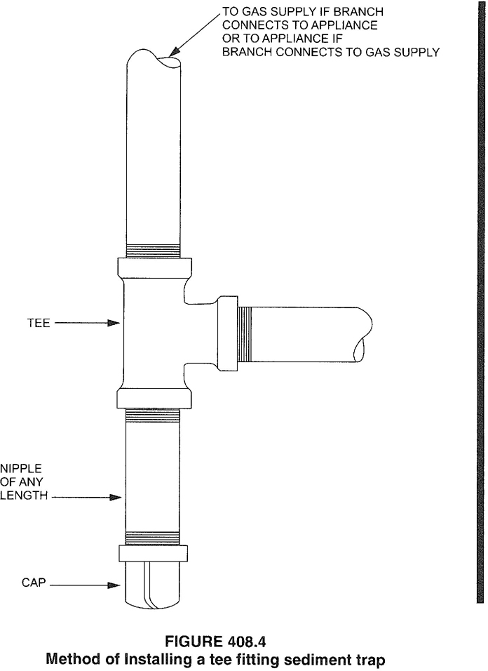
FIGURE 408.4 Method of Installing a tee fitting sediment trap
409.1 General. Piping systems shall be provided with shutoff valves in accordance with this section.
409.1.1 Valve approval. Shutoff valves shall be of an approved type; shall be constructed of materials compatible with the piping; and shall comply with the standard that is applicable for the pressure and application, in accordance with Table 409.1.1.
409.1.2 Prohibited locations. Shutoff valves shall be prohibited in concealed locations and furnace plenums.
409.1.3 Access to shutoff valves. Shutoff valves shall be located in places so as to provide access for operation and shall be installed so as to be protected from damage.
| VALVE STANDARDS | APPLIANCE SHUTOFF VALVE APPLICATION UP TO ½psig PRESSURE | OTHER VALVE APPLICATIONS | ||||
|---|---|---|---|---|---|---|
| UP TO ½psig PRESSURE | UP TO 2 psig PRESSURE | UP TO 5 psig PRESSURE | UP TO 125 psig PRESSURE | |||
| ANSI Z21.15 | X | — | — | — | — | |
| ASME B 16.44 | X | X | Xa | Xb | — | |
| ASME B 16.33 | X | X | X | X | X | |
| For SI: 1 pound per square inch gauge = 6.895 kPa. | ||||||
| a. If labeled 2G. b. If labeled 5G. |
||||||
409.2 Meter valve. Every meter shall be equipped with a shutoff valve located on the supply side of the meter.
409.3 Shutoff valves for multiple-house line systems. Where a single meter is used to supply gas to more than one building or tenant, a separate shutoff valve shall be provided for each building or tenant.
409.3.1 Multiple tenant buildings. In multiple tenant buildings, where a common piping system is installed to supply other than one- and two-family dwellings, shutoff valves shall be provided for each tenant. Each tenant shall have access to the shutoff valve serving that tenant’s space.
409.3.2 Individual buildings. In a common system serving more than one building, shutoff valves shall be installed outdoors at each building.
409.3.3 Identification of shutoff valves. Each house line shutoff valve shall be plainly marked with an identification tag attached by the installer so that the piping systems supplied by such valves are readily identified.
409.4 MP regulator valves. A listed shutoff valve shall be installed immediately ahead of each MP regulator.
409.5 Appliance shutoff valve. Each appliance shall be provided with a shutoff valve in accordance with Section 409.5.1, 409.5.2 or 409.5.3.
409.5.1 Located within same room. The shutoff valve shall be located in the same room as the appliance. The shutoff valve shall be within 6 feet (1829 mm) of the appliance, and shall be installed upstream of the union, connector or quick disconnect device it serves. Such shut-off valves shall be provided with access. Appliance shut-off valves located in the firebox of a fireplace shall be installed in accordance with the appliance manufacturer’s instructions.
409.5.2 Vented decorative appliances and room heaters. Shutoff valves for vented decorative appliances, room heaters and decorative appliances for installation in vented fireplaces shall be permitted to be installed in an area remote from the appliances where such valves are provided with ready access. Such valves shall be permanently identified and shall serve no other appliance. The piping from the shutoff valve to within 6 feet (1829 mm) of the appliance shall be designed, sized and installed in accordance with Sections 401 through 408.
409.5.3 Located at manifold. Where the appliance shut-off valve is installed at a manifold, such shutoff valve shall be located within 50 feet (15 240 mm) of the appliance served and shall be readily accessible and permanently identified. The piping from the manifold to within 6 feet (1829 mm) of the appliance shall be designed, sized and installed in accordance with Sections 401 through 408.
409.6 Shutoff valve for laboratories. Where provided with two or more fuel gas outlets, including table-, bench- and hood-mounted outlets, each laboratory space in educational, research, commercial and industrial occupancies shall be provided with a single dedicated shutoff valve through which all such gas outlets shall be supplied. The dedicated shutoff valve shall be readily accessible, located within the laboratory space served, located adjacent to the egress door from the space and shall be identified by approved signage stating “Gas Shutoff.”
410.1 Pressure regulators. A line pressure regulator shall be installed where the appliance is designed to operate at a lower pressure than the supply pressure. Line gas pressure regulators shall be listed as complying with ANSI Z21.80. Access shall be provided to pressure regulators. Pressure regulators shall be protected from physical damage. Regulators installed on the exterior of the building shall be approved for outdoor installation.
410.2 MP regulators. MP pressure regulators shall comply with the following:
410.3 Venting of regulators. Pressure regulators that require a vent shall be vented directly to the outdoors. The vent shall be designed to prevent the entry of insects, water and foreign objects.
Exception: A vent to the outdoors is not required for regulators equipped with and labeled for utilization with an approved vent-limiting device installed in accordance with the manufacturer’s instructions.
410.3.1 Vent piping. Vent piping for relief vents and breather vents shall be constructed of materials allowed for gas piping in accordance with Section 403. Vent piping shall be not smaller than the vent connection on the pressure regulating device. Vent piping serving relief vents and combination relief and breather vents shall be run independently to the outdoors and shall serve only a single device vent. Vent piping serving only breather vents is permitted to be connected in a manifold arrangement
75where sized in accordance with an approved design that minimizes back-pressure in the event of diaphragm rupture. Regulator vent piping shall not exceed the length specified in the regulator manufacturer’s instructions.
410.4 Excess flow valves. Where automatic excess flow valves are installed, they shall be listed for the application and shall be sized and installed in accordance with the manufacturer’s instructions.
410.5 Flashback arrestor check valve. Where fuel gas is used with oxygen in any hot work operation, a listed protective device that serves as a combination flashback arrestor and backflow check valve shall be installed at an approved location on both the fuel gas and oxygen supply lines. Where the pressure of the piped fuel gas supply is insufficient to ensure such safe operation, approved equipment shall be installed between the gas meter and the appliance that increases pressure to the level required for such safe operation.
411.1 Connecting appliances. Except as required by Section 411.1.1, appliances shall be connected to the piping system by one of the following:
411.1.1 Commercial cooking appliances. Commercial cooking appliances installed on casters and appliances that are moved for cleaning and sanitation purposes shall be connected to the piping system with an appliance connector listed as complying with ANSI Z21.69 or in accordance with Item 1 or 3 of Section 411.1.
411.1.2 Protection against damage. Connectors and tubing shall be installed so as to be protected against physical damage.
411.1.3 Connector installation. Appliance fuel connectors shall be installed in accordance with the manufacturer’s instructions and Sections 411.1.3.1 through 411.1.3.4.
411.1.3.1 Maximum length. Connectors shall have an overall length not to exceed 6 feet (1829 mm). Measurement shall be made along the centerline of the connector. Only one connector shall be used for each appliance.
Exception: Rigid metallic piping used to connect an appliance to the piping system shall be permitted to have a total length greater than 6 feet (1829 mm), provided that the connecting pipe is sized as part of the piping system in accordance with Section 402 and the location of the appliance shutoff valve complies with Section 409.5.
411.1.3.2 Minimum size. Connectors shall have the capacity for the total demand of the connected appliance.
411.1.3.3 Prohibited locations and penetrations. Connectors shall not be concealed within, or extended through, walls, floors, partitions, ceilings or appliance housings.
Exceptions:
- Connectors constructed of materials allowed for piping systems in accordance with Section 403 shall be permitted to pass through walls, floors, partitions and ceilings where installed in accordance with Section 409.5.2 or 409.5.3.
- Rigid steel pipe connectors shall be permitted to extend through openings in appliance housings.
- Fireplace inserts that are factory equipped with grommets, sleeves or other means of protection in accordance with the listing of the appliance.
- Semirigid tubing and listed connectors shall be permitted to extend through an opening in an appliance housing, cabinet or casing where the tubing or connector is protected against damage.
411.1.3.4 Shutoff valve. A shutoff valve not less than the nominal size of the connector shall be installed ahead of the connector in accordance with Section 409.5.
411.1.4 Movable appliances. Where appliances are equipped with casters or are otherwise subject to periodic movement or relocation for purposes such as routine cleaning and maintenance, such appliances shall be connected to the supply system piping by means of an approved flexible connector designed and labeled for the application. Such flexible connectors shall be installed and protected against physical damage in accordance with the manufacturer’s installation instructions.
411.1.5 (IFGS) Connection of gas engine-powered air conditioners. Internal combustion engines shall not be rigidly connected to the gas supply piping.
76411.1.6 Unions. A union fitting shall be provided for appliances connected by rigid metallic pipe. Such unions shall be accessible and located within 6 feet (1829 mm) of the appliance.
411.1.6 Unions. A union fitting shall be provided for appliances connected by rigid metallic pipe. Such unions shall be accessible and located within 6 feet (1829 mm) of the appliance.
411.2 Manufactured home connections. Manufactured homes shall be connected to the distribution piping system by one of the following materials:
411.3 Suspended low-intensity infrared tube heaters. Suspended low-intensity infrared tube heaters shall be connected to the building piping system with a connector listed for the application complying with ANSI Z21.24/CGA 6.10. The connector shall be installed as specified by the tube heater manufacturer’s instructions.
[F] 412.1 General. Motor fuel-dispensing facilities for LP-gas fuel shall be in accordance with this section and the International Fire Code. The operation of LP-gas motor fuel-dispensing facilities shall be regulated by the International Fire Code
[F] 412.2 Storage and dispensing. Storage vessels and equipment used for the storage or dispensing of LP-gas shall be approved or listed in accordance with Sections 412.3 and 412.4
[F] 412.3 Approved equipment. Containers: pressure-relief devices, including pressure-relief valves; and pressure regulators and piping used for LP-gas shall be approved.
[F] 412.4 Listed equipment. Hoses, hose connections, vehicle fuel connections, dispensers, LP-gas pumps and electrical equipment used for LP-gas shall be listed.
[F] 412.5 Attendants. Motor vehicle fueling operations shall be conducted by qualified attendants or in accordance with Section 412.8 by persons trained in the proper handling of LP-gas.
[F] 412.6 Location. In addition to the fuel dispensing requirements of the International Fire Code, the point of transfer for dispensing operations shall be 25 feet (7620 mm) or more from buildings having combustible exterior wall surfaces, buildings having noncombustible exterior wall surfaces that are not part of a 1-hour fire-resistance-rated assembly or buildings having combustible overhangs, property which could be built on public streets, or sidewalks and railroads; and at least 10 feet (3048 mm) from driveways and buildings having noncombustible exterior wall surfaces that are part of a fire-resistance-rated assembly having a rating of 1 hour or more.
Exception: The point of transfer for dispensing operations need not be separated from canopies providing weather protection for the dispensing equipment constructed in accordance with the International Building Code.
Liquefied petroleum gas containers shall be located in accordance with the International Fire Code. Liquefied petroleum gas storage and dispensing equipment shall be located outdoors and in accordance with the International Fire Code.
[F] 412.7 Installation of dispensing devices and equipment. The installation and operation of LP-gas dispensing systems shall be in accordance with this section and the International Fire Code. Liquefied petroleum gas dispensers and dispensing stations shall be installed in accordance with manufacturers’ specifications and their listing.
[F] 412.7.1 Valves. A manual shutoff valve and an excess flow-control check valve shall be located in the liquid line between the pump and the dispenser inlet where the dispensing device is installed at a remote location and is not part of a complete storage and dispensing unit mounted on a common base.
An excess flow-control check valve or an emergency shutoff valve shall be installed in or on the dispenser at the point at which the dispenser hose is connected to the liquid piping. A differential backpressure valve shall be considered equivalent protection. A listed shutoff valve shall be located at the discharge end of the transfer hose.
[F] 412.7.2 Hoses. Hoses and piping for the dispensing of LP-gas shall be provided with hydrostatic relief valves. The hose length shall not exceed 18 feet (5486 mm). An approved method shall be provided to protect the hose against mechanical damage.
[F] 412.7.3 Vehicle impact protection. Vehicle impact protection for LP-gas storage containers, pumps and dispensers shall be provided in accordance with the International Fire Code.
[F] 412.8 Private fueling of motor vehicles. Self-service LP-gas dispensing systems, including key, code and card lock dispensing systems, shall not be open to the public and shall be limited to the filling of permanently mounted fuel containers on LP-gas powered vehicles. In addition to the requirements in the International Fire Code, self-service LP-gas dispensing systems shall be provided with an emergency shutoff switch located within 100 feet (30 480 mm) of, but not less than 20 feet (6096 mm) from, dispensers and the owner of the dispensing facility shall ensure the safe operation of the system and the training of users.
[F] 413.1 General. Motor fuel-dispensing facilities for CNG fuel shall be in accordance with this section and the International Fire Code. The operation of CNG motor fuel-dispensing facilities shall be regulated by the International Fire Code.
[F] 413.2 General. Storage vessels and equipment used for the storage, compression or dispensing of CNG shall be
77approved or listed in accordance with Sections 413.2.1 through 413.2.3.
[F] 413.2.1 Approved equipment. Containers; compressors; pressure-relief devices, including pressure-relief valves; and pressure regulators and piping used for CNG shall be approved.
[F] 413.2.2 Listed equipment. Hoses, hose connections, dispensers, gas detection systems and electrical equipment used for CNG shall be listed. Vehicle fueling connections shall be listed and labeled.
[F] 413.2.3 General. Residential fueling appliances shall be listed. The capacity of a residential fueling appliance shall not exceed 5 standard cubic feet per minute (0.14 standard cubic meter/min) of natural gas.
[F] 413.3 Location of dispensing operations and equipment. Compression, storage and dispensing equipment shall be located above ground outside.
Exceptions:
- Compression, storage or dispensing equipment is allowed in buildings of noncombustible construction, as set forth in the International Building Code, which are unenclosed for three-quarters or more of the perimeter.
- Compression, storage and dispensing equipment is allowed to be located indoors or in vaults in accordance with the International Fire Code.
- Residential fueling appliances and equipment shall be allowed to be installed indoors in accordance with the equipment manufacturer’s instructions and Section 413.4.3.
[F] 413.3.1 Location on property. In addition to the fuel-dispensing requirements of the International Fire Code, compression, storage and dispensing equipment not located in vaults complying with the International Fire Code and other than residential fueling appliances shall not be installed:
- Beneath power lines.
- Less than 10 feet (3048 mm) from the nearest building or property that could be built on, public street, sidewalk or source of ignition.
Exception: Dispensing equipment need not be separated from canopies that provide weather protection for the dispensing equipment and are constructed in accordance with the International Building Code.
- Less than 25 feet (7620 mm) from the nearest rail of any railroad track.
- Less than 50 feet (15 240 mm) from the nearest rail of any railroad main track or any railroad or transit line where power for train propulsion is provided by an outside electrical source, such as third rail or overhead catenary.
- Less than 50 feet (15 240 mm) from the vertical plane below the nearest overhead wire of a trolley bus line.
[F] 413.4 Residential fueling appliance installation. Residential fueling appliances shall be installed in accordance with Sections 413.4.1 through 413.4.3.
[F] 413.4.1 Gas connections. Residential fueling appliances shall be connected to the premises’ gas piping system without causing damage to the piping system or the connection to the internal appliance apparatus.
[F] 413.4.2 Outdoor installation. Residential fueling appliances located outdoors shall be installed on a firm, noncombustible base.
[F] 413.4.3 Indoor installation. Where located indoors, residential fueling appliances shall be vented to the outdoors. A gas detector set to operate at one-fifth of the lower limit of flammability of natural gas shall be installed in the room or space containing the appliance. The detector shall be located within 6 inches (152 mm) of the highest point in the room or space. The detector shall stop the operation of the appliance and activate an audible or a visual alarm.
[F] 413.5 Private fueling of motor vehicles. Self-service CNG-dispensing systems, including key, code and card lock dispensing systems, shall be limited to the filling of permanently mounted fuel containers on CNG-powered vehicles.
In addition to the requirements in the International Fire Code, the owner of a self-service CNG-dispensing facility shall ensure the safe operation of the system and the training of users.
[F] 413.6 Pressure regulators. Pressure regulators shall be designed, installed or protected so their operation will not be affected by the elements (freezing rain, sleet, snow, ice, mud or debris). This protection is allowed to be integral with the regulator.
[F] 413.7 Valves. Piping to equipment shall be provided with a remote manual shutoff valve. Such valve shall be provided with ready access.
[F] 413.8 Emergency shutdown control. An emergency shutdown device shall be located within 75 feet (22 860 mm) of, but not less than 25 feet (7620 mm) from, dispensers and shall also be provided in the compressor area. Upon activation, the emergency shutdown system shall automatically shut off the power supply to the compressor and close valves between the main gas supply and the compressor and between the storage containers and dispensers.
[F] 413.9 Discharge of CNG from motor vehicle fuel storage containers. The discharge of CNG from motor vehicle fuel cylinders for the purposes of maintenance, cylinder certification, calibration of dispensers or other activities shall be in accordance with this section. The discharge of CNG from motor vehicle fuel cylinders shall be accomplished through a closed transfer system or an approved method of atmospheric venting in accordance with Section 413.9.1 or 413.9.2.
[F] 413.9.1 Closed transfer system. A documented procedure which explains the logical sequence for discharging the cylinder shall be provided to the code official for review and approval. The procedure shall include what actions the operator will take in the event of a low-pressure or high-pressure natural gas release during the discharging
78activity. A drawing illustrating the arrangement of piping, regulators and equipment settings shall be provided to the code official for review and approval. The drawing shall illustrate the piping and regulator arrangement and shall be shown in spatial relation to the location of the compressor, storage vessels and emergency shutdown devices.
[F] 413.9.2 Atmospheric venting. Atmospheric venting of motor vehicle fuel cylinders shall be in accordance with Sections 413.9.2.1 through 413.9.2.6.
[F] 413.9.2.1 Plans and specifications. A drawing illustrating the location of the vessel support, piping, the method of grounding and bonding, and other requirements specified herein shall be provided to the code official for review and approval.
[F] 413.9.2.2 Cylinder stability. A method of rigidly supporting the vessel during the venting of CNG shall be provided. The selected method shall provide not less than two points of support and shall prevent the horizontal and lateral movement of the vessel. The system shall be designed to prevent the movement of the vessel based on the highest gas-release velocity through valve orifices at the vessel’s rated pressure and volume. The structure or appurtenance shall be constructed of noncombustible materials.
[F] 413.9.2.3 Separation. The structure or appurtenance used for stabilizing the cylinder shall be separated from the site equipment, features and exposures and shall be located in accordance with Table 413.9.2.3.
[F] TABLE 413.9.2.3
SEPARATION DISTANCE FOR ATMOSPHERIC VENTING OF CNGEQUIPMENT OR FEATURE MINIMUM SEPARATION (feet) Buildings 25 Building openings 25 Lot lines 15 Public ways 15 Vehicles 25 CNG compressor and storage vessels 25 CNG dispensers 25 For SI: 1 foot = 304.8 mm. [F] 413.9.2.4 Grounding and bonding. The structure or appurtenance used for supporting the cylinder shall be grounded in accordance with NFPA 70. The cylinder valve shall be bonded prior to the commencement of venting operations.
[F] 413.9.2.5 Vent tube. A vent tube that will divert the gas flow to the atmosphere shall be installed on the cylinder prior to the commencement of the venting and purging operation. The vent tube shall be constructed of pipe or tubing materials approved for use with CNG in accordance with the International Fire Code.
The vent tube shall be capable of dispersing the gas a minimum of 10 feet (3048 mm) above grade level. The vent tube shall not be provided with a rain cap or other feature which would limit or obstruct the gas flow.
At the connection fitting of the vent tube and the CNG cylinder, a listed bidirectional detonation flame arrester shall be provided.
[F] 413.9.2.6 Signage. Approved NO SMOKING signs shall be posted within 10 feet (3048 mm) of the cylinder support structure or appurtenance. Approved CYLINDER SHALL BE BONDED signs shall be posted on the cylinder support structure or appurtenance.
414.1 Use of air or oxygen under pressure. Where air or oxygen under pressure is used in connection with the gas supply, effective means such as a backpressure regulator and relief valve shall be provided to prevent air or oxygen from passing back into the gas piping. Where oxygen is used, installation shall be in accordance with NFPA 51.
414.2 Interconnections for standby fuels. Where supplementary gas for standby use is connected downstream from a meter or a service regulator where a meter is not provided, a device to prevent backflow shall be installed. A three-way valve installed to admit the standby supply and at the same time shut off the regular supply shall be permitted to be used for this purpose.
415.1 Interval of support. Piping shall be supported at intervals not exceeding the spacing specified in Table 415.1. Spacing of supports for CSST shall be in accordance with the CSST manufacturer’s instructions.
| STEEL PIPE, NOMINAL SIZE OF PIPE (inches) | SPACING OF SUPPORTS (feet) | NOMINAL SIZE OF TUBING (SMOOTH-WALL) (inch O.D.) | SPACING OF SUPPORTS (feet) |
|---|---|---|---|
| ½ | 6 | ½ | 4 |
| ¾ or 1 | 8 | 5/8 or ¾ | 6 |
| 1 ¼ or larger (horizontal) | 10 | 7/8 or 1 (horizontal) | 8 |
| 1 ¼ or larger (vertical) | Every floor level | 1 or larger (vertical) | Every floor level |
| For SI: 1 inch = 25.4 mm, 1 foot = 304.8 mm. | |||
416.1 General. Overpressure protection devices shall be provided in accordance with this section to prevent the pressure in the piping system from exceeding the pressure that would cause unsafe operation of any connected and properly adjusted appliances.
79416.2 Protection methods. The requirements of this section shall be considered to be met and a piping system deemed to have overpressure protection where a service or line pressure regulator plus one other device are installed such that the following occur:
416.3 Device maintenance. The pressure regulating, limiting and relieving devices shall be maintained; and inspection procedures shall be devised or instrumentation installed to detect failures or malfunctions of such devices; and replacements or repairs shall be made.
416.4 Where required. A pressure-relieving or pressure-limiting device shall not be required where: (1) the gas does not contain materials that could seriously interfere with the operation of the service or line pressure regulator; (2) the operating pressure of the gas source is 60 psi (414 kPa) or less; and (3) the service or line pressure regulator has all of the following design features or characteristics:
416.5 Devices. Pressure-relieving or pressure-limiting devices shall be one of the following:
The devices shall be installed either as an integral part of the service or line pressure regulator or as separate units. Where separate pressure-relieving or pressure-limiting devices are installed, they shall comply with Sections 416.5.1 through 416.5.6.
81 82416.5.1 Construction and installation. Pressure relieving and pressure-limiting devices shall be constructed of materials so that the operation of the devices will not be impaired by corrosion of external parts by the atmosphere or of internal parts by the gas. Pressure-relieving and pressure-limiting devices shall be designed and installed so that they can be operated to determine whether the valve is free. The devices shall also be designed and installed so that they can be tested to determine the pressure at which they will operate and examined for leakage when in the closed position.
416.5.2 External control piping. External control piping shall be protected from falling objects, excavations and other causes of damage and shall be designed and installed so that damage to any control piping will not render both the regulator and the overpressure protective device inoperative.
416.5.3 Setting. Each pressure-relieving or pressure-limiting device shall be set so that the pressure does not exceed a safe level beyond the maximum allowable working pressure for the connected piping and appliances.
416.5.4 Unauthorized operation. Where unauthorized operation of any shutoff valve can make a pressure relieving valve or pressure limiting device inoperative, one of I the following shall apply:
- The valve shall be locked in the open position. Authorized personnel shall be instructed in the importance of leaving the shutoff valve open and of being present while the shutoff valve is closed so that it can be locked in the open position before leaving the premises.
- Duplicate relief valves shall be installed, each having adequate capacity to protect the system, and the isolating valves and three-way valves shall be arranged so that only one safety device can be rendered inoperative at a time.
416.5.5 Vents. The discharge stacks, vents and outlet parts of all pressure-relieving and pressure-limiting devices shall be located so that gas is safely discharged to the outdoors. Discharge stacks and vents shall be designed to prevent the entry of water, insects and other foreign material
80that could cause blockage. The discharge stack or vent line shall be at least the same size as the outlet of the pressure-relieving device.
416.5.6 Size of fittings, pipe and openings. The fittings, pipe and openings located between the system to be protected and the pressure-relieving device shall be sized to prevent hammering of the valve and to prevent impairment of relief capacity.
501.1 Scope. This chapter shall govern the installation, maintenance, repair and approval of factory-built chimneys, chimney liners, vents and connectors and the utilization of masonry chimneys serving gas-fired appliances. The requirements for the installation, maintenance, repair and approval of factory-built chimneys, chimney liners, vents and connectors serving appliances burning fuels other than fuel gas shall be regulated by the International Mechanical Code. The construction, repair, maintenance and approval of masonry chimneys shall be regulated by the International Building Code.
501.2 General. Every appliance shall discharge the products of combustion to the outdoors, except for appliances exempted by Section 501.8.
501.3 Masonry chimneys. Masonry chimneys shall be constructed in accordance with Section 503.5.3 and the International Building Code.
501.4 Minimum size of chimney or vent. Chimneys and vents shall be sized in accordance with Sections 503 and 504.
501.5 Abandoned inlet openings. Abandoned inlet openings in chimneys and vents shall be closed by an approved method.
501.6 Positive pressure. Where an appliance equipped with a mechanical forced draft system creates a positive pressure in the venting system, the venting system shall be designed for positive pressure applications.
501.7 Connection to fireplace. Connection of appliances to chimney flues serving fireplaces shall be in accordance with Sections 501.7.1 through 501.7.3.
501.7.1 Closure and access. A noncombustible seal shall be provided below the point of connection to prevent entry of room air into the flue. Means shall be provided for access to the flue for inspection and cleaning.
501.7.2 Connection to factory-built fireplace flue. An appliance shall not be connected to a flue serving a factory-built fireplace unless the appliance is specifically listed for such installation. The connection shall be made in accordance with the appliance manufacturer’s installation instructions.
501.7.3 Connection to masonry fireplace flue. A connector shall extend from the appliance to the flue serving a masonry fireplace such that the flue gases are exhausted directly into the flue. The connector shall be accessible or removable for inspection and cleaning of both the connector and the flue. Listed direct connection devices shall be installed in accordance with their listing.
501.8 Appliances not required to be vented. The following appliances shall not be required to be vented.
Where the appliances listed in Items 5 through 11 above are installed so that the aggregate input rating exceeds 20 British thermal units (Btu) per hour per cubic feet (207 watts per m3) of volume of the room or space in which such appliances are installed, one or more shall be provided with venting systems or otherapproved means for conveying the vent gases to the outdoor atmosphere so that the aggregate input rating of the remaining unvented appliances does not exceed 20 Btu per hour per cubic foot (207 watts per m3). Where the room or space in which the appliance is installed is directly connected to another room or space by a doorway, archway or other opening of comparable size that cannot be closed, the volume of such adjacent room or space shall be permitted to be included in the calculations.
501.9 Chimney entrance. Connectors shall connect to a masonry chimney flue at a point not less than 12 inches (305 mm) above the lowest portion of the interior of the chimney flue.
501.10 Connections to exhauster. Appliance connections to a chimney or vent equipped with a power exhauster shall be made on the inlet side of the exhauster. Joints on the positive pressure side of the exhauster shall be sealed to prevent flue-gas leakage as specified by the manufacturer’s installation instructions for the exhauster.
501.11 Masonry chimneys. Masonry chimneys utilized to vent appliances shall be located, constructed and sized as
83specified in the manufacturer’s installation instructions for the appliances being vented and Section 503.
501.12 Residential and low-heat appliances flue lining systems. Flue lining systems for use with residential-type and low-heat appliances shall be limited to the following:
501.13 Category 1 appliance flue lining systems. Flue lining systems for use with Category I appliances shall be limited to the following:
501.14 Category II, III and IV appliance venting systems. The design, sizing and installation of vents for Category II, III and IV appliances shall be in accordance with the appliance manufacturer’s installation instructions.
501.15 Existing chimneys and vents. Where an appliance is permanently disconnected from an existing chimney or vent, or where an appliance is connected to an existing chimney or vent during the process of a new installation, the chimney or vent shall comply with Sections 501.15.1 through 501.15.4.
501.15.1 Size. The chimney or vent shall be resized as necessary to control flue gas condensation in the interior of the chimney or vent and to provide the appliance or appliances served with the required draft. For Category I appliances, the resizing shall be in accordance with Section 502.
501.15.2 Flue passageways. The flue gas passageway shall be free of obstructions and combustible deposits and shall be cleaned if previously used for venting a solid or liquid fuel-burning appliance or fireplace. The flue liner, chimney inner wall or vent inner wall shall be continuous and shall be free of cracks, gaps, perforations or other damage or deterioration which would allow the escape of combustion products, including gases, moisture and creosote.
501.15.3 Cleanout. Masonry chimney flues shall be provided with a cleanout opening having a minimum height of 6 inches (152 mm). The upper edge of the opening shall be located not less than 6 inches (152 mm) below the lowest chimney inlet opening. The cleanout shall be provided with a tight-fitting, noncombustible cover.
501.15.4 Clearances. Chimneys and vents shall have airspace clearance to combustibles in accordance with the International Building Code and the chimney or vent manufacturer’s installation instructions.
Exception: Masonry chimneys without the required airspace clearances shall be permitted to be used if lined or relined with a chimney lining system listed for use in chimneys with reduced clearances in accordance with UL 1777. The chimney clearance shall be not less than permitted by the terms of the chimney liner listing and the manufacturer’s instructions.
501.15.4.1 Fireblocking. Noncombustible fireblocking shall be provided in accordance with the International Building Code.
502.1 General. All vents, except as provided in Section 503.7, shall be listed and labeled. Type B and BW vents shall be tested in accordance with UL 441. Type L vents shall be tested in accordance with UL 641. Vents for Category II and III appliances shall be tested in accordance with UL 1738. Plastic vents for Category IV appliances shall not be required to be listed and labeled where such vents are as specified by the appliance manufacturer and are installed in accordance with the appliance manufacturer’s installation instructions.
502.2 Connectors required. Connectors shall be used to connect appliances to the vertical chimney or vent, except where the chimney or vent is attached directly to the appliance. Vent connector size, material, construction and installation shall be in accordance with Section 503.
502.3 Vent application. The application of vents shall be in accordance with Table 503.4.
502.4 Insulation shield. Where vents pass through insulated assemblies, an insulation shield constructed of steel having a minimum thickness of 0.0187 inch (0.4712 mm) (No. 26 gage) shall be installed to provide clearance between the vent and the insulation material. The clearance shall not be less than the clearance to combustibles specified by the vent manufacturer’s installation instructions. Where vents pass through attic space, the shield shall terminate not less than 2 inches (51 mm) above the insulation materials and shall be secured in place to prevent displacement. Insulation shields provided as part of a listed vent system shall be installed in accordance with the manufacturer’s installation instructions.
502.5 Installation. Vent systems shall be sized, installed and terminated in accordance with the vent and appliance manufacturer’s installation instructions and Section 503.
502.6 Support of vents. All portions of vents shall be adequately supported for the design and weight of the materials employed.
502.7 Protection against physical damage. In concealed locations, where a vent is installed through holes or notches in studs, joists, rafters or similar members less than 1½ inches (38 mm) from the nearest edge of the member, the vent shall be protected by shield plates. Protective steel shield plates having a minimum thickness of 0.0575 inch (1.463 mm)
84(No. 16 gage) shall cover the area of the vent where the member is notched or bored and shall extend a minimum of 4 inches (102 mm) above sole plates, below top plates and to each side of a stud, joist or rafter.
503.1 General. The venting of appliances shall be in accordance with Sections 503.2 through 503.16.
503.2 Venting systems required. Except as permitted in Sections 503.2.1 through 503.2.4 and 501.8, all appliances shall be connected to venting systems.
503.2.1 Ventilating hoods. Ventilating hoods and exhaust systems shall be permitted to be used to vent appliances installed in commercial applications and to vent industrial appliances, such as where the process itself requires fume disposal.
503.2.2 Well-ventilated spaces. Where located in a large and well-ventilated space, industrial appliances shall be permitted to be operated by discharging the flue gases directly into the space.
503.2.3 Direct-vent appliances. Listed direct-vent appliances shall be installed in accordance with the manufacturer’s instructions and Section 503.8, Item 3.
503.2.4 Appliances with integral vents. Appliances incorporating integral venting means shall be installed in accordance with the manufacturer’s instructions and Section 503.8, Items 1 and 2.
503.2.5 Incinerators. Commercial-industrial-type incinerators shall be vented in accordance with NFPA 82.
503.3 Design and construction. Venting systems shall be designed and constructed so as to convey all flue and vent gases to the outdoors.
503.3.1 Appliance draft requirements. A venting system shall satisfy the draft requirements of the appliance in accordance with the manufacturer’s instructions.
503.3.2 Design and construction. Appliances required to be vented shall be connected to a venting system designed and installed in accordance with the provisions of Sections 503.4 through 503.16.
503.3.3 Mechanical draft systems. Mechanical draft systems shall comply with the following:
- Mechanical draft systems shall be listed and shall be installed in accordance with the manufacturer’s installation instructions for both the appliance and the mechanical draft system.
- Appliances requiring venting shall be permitted to be vented by means of mechanical draft systems of either forced or induced draft design.
- Forced draft systems and all portions of induced draft systems under positive pressure during operation shall be designed and installed so as to prevent leakage of flue or vent gases into a building.
- Vent connectors serving appliances vented by natural draft shall not be connected into any portion of mechanical draft systems operating under positive pressure.
- Where a mechanical draft system is employed, provisions shall be made to prevent the flow of gas to the main burners when the draft system is not performing so as to satisfy the operating requirements of the appliance for safe performance.
- The exit terminals of mechanical draft systems shall be not less than 7 feet (2134 mm) above finished ground level where located adjacent to public walkways and shall be located as specified in Section 503.8, Items 1 and 2.
503.3.4 Ventilating hoods and exhaust systems. Ventilating hoods and exhaust systems shall be permitted to be used to vent appliances installed in commercial applications. Where automatically operated appliances, other than commercial cooking appliances, are vented through a ventilating hood or exhaust system equipped with a damper or with a power means of exhaust, provisions shall be made to allow the flow of gas to the main burners only when the damper is open to a position to properly vent the appliance and when the power means of exhaust is in operation.
503.3.5 Air ducts and furnace plenums. Venting systems shall not extend into or pass through any fabricated air duct or furnace plenum.
503.3 .6 Above-ceiling air-handling spaces. Where a venting system passes through an above-ceiling air-handling space or other nonducted portion of an air-handling system, the venting system shall conform to one of the following requirements:
- The venting system shall be a listed special gas vent; other venting system serving a Category III or Category IV appliance; or other positive pressure vent, with joints sealed in accordance with the appliance or vent manufacturer’s instructions.
- The venting system shall be installed such that fittings and joints between sections are not installed in the above-ceiling space.
- The venting system shall be installed in a conduit or enclosure with sealed joints separating the interior of the conduit or enclosure from the ceiling space.
503.4 Type of venting system to be used. The type of venting system to be used shall be in accordance with Table 503.4.
85503.4.1 Plastic piping. Plastic piping used for venting appliances listed for use with such venting materials shall be approved.
503.4.1.1 Plastic vent joints. Plastic pipe and fittings used to vent appliances shall be installed in accordance with the appliance manufacturer’s installation instructions. Where a primer is required, it shall be of a contrasting color.
| APPLIANCES | TYPE OF VENTING SYSTEM |
|---|---|
| Listed Category I appliances Listed appliances equipped with draft hood Appliances listed for use with Type B gas vent |
Type B gas vent (Section 503.6) Chimney (Section 503.5) Single-wall metal pipe (Section 503.7) Listed chimney lining system for gas venting (Section 503.5.3) Special gas vent listed for these appliances (Section 503.4.2) |
| Listed vented wall furnaces | Type B-W gas vent (Sections 503.6, 608) |
| Category II appliances | As specified or furnished by manufacturers of listed appliances (Sections 503.4.1, 503.4.2) |
| Category III appliances | As specified or furnished by manufacturers of listed appliances (Sections 503.4.1,503.4.2) |
| Category IV appliances | As specified or furnished by manufacturers of listed appliances (Sections 503.4.1, 503.4.2) |
| Incinerators | In accordance with NFPA 82 |
| Appliances that can be converted for use with solid fuel | Chimney (Section 503.5) |
| Unlisted combination gas and oil-burning appliances | Chimney (Section 503.5) |
| Listed combination gas and oil-burning appliances | Type L vent (Section 503.6) or chimney (Section 503.5) |
| Combination gas and solid fuel-burning appliances | Chimney (Section 503.5) |
| Appliances listed for use with chimneys only | Chimney (Section 503.5) |
| Unlisted appliances | Chimney (Section 503.5) |
| Decorative appliances in vented fireplaces | Chimney |
| Gas-fired toilets | Single-wall metal pipe (Section 626) |
| Direct-vent appliances | See Section 503.2.3 |
| Appliances with integral vent | See Section 503.2.4 |
503.4.2 Special gas vent. Special gas vent shall be listed and installed in accordance with the special gas vent manufacturer’s installation instructions.
503.5 Masonry, metal and factory-built chimneys. Masonry, metal and factory-built chimneys shall comply with Sections 503.5.1 through 503.5.10.
503.5.1 Factory-built chimneys. Factory-built chimneys shall be installed in accordance with the manufacturer’s installation instructions. Factory-built chimneys used to vent appliances that operate at a positive vent pressure shall be listed for such application.
503.5.2 Metal chimneys. Metal chimneys shall be built and installed in accordance with NFPA 211.
503.5.3 Masonry chimneys. Masonry chimneys shall be built and installed in accordance with NFPA 211 and shall be lined with approved clay flue lining, a listed chimney lining system or other approved material that will resist corrosion, erosion, softening or cracking from vent gases at temperatures up to 1,800°F (982°C).
Exception: Masonry chimney flues serving listed gas appliances with draft hoods, Category I appliances and other gas appliances listed for use with Type B vents shall be permitted to be lined with a chimney lining system specifically listed for use only with such appliances. The liner shall be installed in accordance with the liner manufacturer’s installation instructions. A permanent identifying label shall be attached at the point where the connection is to be made to the liner. The label shall read: “This chimney liner is for appliances that burn gas only. Do not connect to solid or liquid fuel-burning appliances or incinerators.”
For installation of gas vents in existing masonry chimneys, see Section 503.6.3.
503.5.4 Chimney termination. Chimneys for residential-type or low-heat appliances shall extend at least 3 feet (914 mm) above the highest point where they pass through a roof of a building and at least 2 feet (610 mm) higher than any portion of a building within a horizontal distance of 10 feet (3048 mm). Chimneys for medium-heat appliances shall extend at least 10 feet (3048 mm) higher than any portion of any building within 25 feet (7620 mm). Chimneys shall extend at least 5 feet (1524 mm) above the highest connected appliance draft hood outlet or flue collar. Decorative shrouds shall not be installed at the termination of factory-built chimneys except where such shrouds are listed and labeled for use with the specific factory-built chimney system and are installed in accordance with the manufacturer’s installation instructions.
503.5.5 Size of chimneys. The effective area of a chimney venting system serving listed appliances with draft hoods, Category I appliances and other appliances listed for use with Type B vents shall be determined in accordance with one of the following methods:
- The provisions of Section 504. 86
- For sizing an individual chimney venting system for a single appliance with a draft hood, the effective areas of the vent connector and chimney flue shall be not less than the area of the appliance flue collar or draft hood outlet, nor greater than seven times the draft hood outlet area.
- For sizing a chimney venting system connected to two appliances with draft hoods, the effective area of the chimney flue shall be not less than the area of the larger draft hood outlet plus 50 percent of the area of the smaller draft hood outlet, nor greater than seven times the smallest draft hood outlet area.
- Chimney venting systems using mechanical draft shall be sized in accordance with approved engineering methods.
- Other approved engineering methods.
503.5.6 Inspection of chimneys. Before replacing an existing appliance or connecting a vent connector to a chimney, the chimney passageway shall be examined to ascertain that it is clear and free of obstructions and it shall be cleaned if previously used for venting solid or liquid fuel-burning appliances or fireplaces.
503.5.6.1 Chimney lining. Chimneys shall be lined in accordance with NFPA 211.
Exception: Where an existing chimney complies with Sections 503.5.6 through 503.5.6.3 and its sizing is in accordance with Section 503.5.5, its continued use shall be allowed where the appliance vented by such chimney is replaced by an appliance of similar type, input rating and efficiency.
503.5.6.2 Cleanouts. Cleanouts shall be examined to determine if they will remain tightly closed when not in use.
503.5.6.3 Unsafe chimneys. Where inspection reveals that an existing chimney is not safe for the intended application, it shall be repaired, rebuilt, lined, relined or replaced with a vent or chimney to conform to NFPA 211 and it shall be suitable for the appliances to be vented.
503.5.7 Chimneys serving appliances burning other fuels. Chimneys serving appliances burning other fuels shall comply with Sections 503.5.7.1 through 503.5.7.4.
503.5.7.1 Solid fuel-burning appliances. An appliance shall not be connected to a chimney flue serving a separate appliance designed to burn solid fuel.
503.5.7.2 Liquid fuel-burning appliances. Where one chimney flue serves gas appliances and liquid fuel-burning appliances, the appliances shall be connected through separate openings or shall be connected through a single opening where joined by a suitable fitting located as close as practical to the chimney. Where two or more openings are provided into one chimney flue, they shall be at different levels. Where the appliances are automatically controlled, they shall be equipped with safety shutoff devices.
503.5.7.3 Combination gas and solid fuel-burning appliances. A combination gas- and solid fuel-burning appliance shall be permitted to be connected to a single chimney flue where equipped with a manual reset device to shut off gas to the main burner in the event of sustained backdraft or flue gas spillage. The chimney flue shall be sized to properly vent the appliance.
503.5.7.4 Combination gas- and oil fuel-burning appliances. A listed combination gas- and oil fuel-burning appliance shall be permitted to be connected to a single chimney flue. The chimney flue shall be sized to properly vent the appliance.
503.5.8 Support of chimneys. All portions of chimneys shall be supported for the design and weight of the materials employed. Factory-built chimneys shall be supported and spaced in accordance with the manufacturer’s installation instructions.
503.5.9 Cleanouts. Where a chimney that formerly carried flue products from liquid or solid fuel-burning appliances is used with an appliance using fuel gas, an accessible cleanout shall be provided. The cleanout shall have a tight-fitting cover and shall be installed so its upper edge is at least 6 inches (152 mm) below the lower edge of the lowest chimney inlet opening.
503.5.10 Space surrounding lining or vent. The remaining space surrounding a chimney liner, gas vent, special gas vent or plastic piping installed within a masonry chimney flue shall not be used to vent another appliance. The insertion of another liner or vent within the chimney as provided in this code and the liner or vent manufacturer’s instructions shall not be prohibited.
The remaining space surrounding a chimney liner, gas vent, special gas vent or plastic piping installed within a masonry, metal or factory-built chimney shall not be used to supply combustion air. Such space shall not be prohibited from supplying combustion air to direct-vent appliances designed for installation in a solid fuel-burning fireplace and installed in accordance with the manufacturer’s installation instructions.
503.6 Gas vents. Gas vents shall comply with Sections 503.6.1 through 503.6.13 (see Section 202, Definitions).
503.6.1 Installation, general. Gas vents shall be installed in accordance with the manufacturer’s installation instructions.
503.6.2 Type B-W vent capacity. A Type B-W gas vent shall have a listed capacity not less than that of the listed vented wall furnace to which it is connected.
503.6.3 Gas vents installed within masonry chimneys. Gas vents installed within masonry chimneys shall be installed in accordance with the manufacturer’s installation instructions. Gas vents installed within masonry chimneys shall be identified with a permanent label installed at the point where the vent enters the chimney. The label shall contain the following language: “This gas vent is for appliances that burn gas. Do not connect to solid or liquid fuel-burning appliances or incinerators.”
87503.6.4 Gas vent terminations. A. gas vent shall terminate in accordance with one of the following:
- Gas vents that are 12 inches (305 mm) or less in size and located not less than 8 feet (2438 mm) from a vertical wall or similar obstruction shall terminate above the roof in accordance with Figure 503.6.4.
- Gas vents that are over 12 inches (305 mm) in size or are located less than 8 feet (2438 mm) from a vertical wall or similar obstruction shall terminate not less than 2 feet (610 mm) above the highest point where they pass through the roof and not less than 2 feet (610 mm) above any portion of a building within 10 feet (3048 mm) horizontally.
- As provided for industrial appliances in Section 503.2.2.
- As provided for direct-vent systems in Section 503.2.3.
- As provided for appliances with integral vents in Section 503.2.4.
- As provided for mechanical draft systems in Section 503.3.3.
- As provided for ventilating hoods and exhaust systems in Section 503.3.4.
FIGURE 503.6.4
TERMINATION LOCATIONS FOR GAS VENTS WITH LISTED CAPS 12 INCHES OR LESS IN SIZE AT LEAST 8 FEET FROM A VERTICAL WALL503.6.4.1 Decorative shrouds. Decorative shrouds shall not be installed at the termination of gas vents except where such shrouds are listed for use with the specific gas venting system and are installed in accordance with manufacturer’s installation instructions.
503.6.5 Minimum height. A Type B or L gas vent shall terminate at least 5 feet (1524 mm) in vertical height above the highest connected appliance draft hood or flue collar. A Type B-W gas vent shall terminate at least 12 feet (3658 mm) in vertical height above the bottom of the wall furnace.
503.6.6 Roof terminations. Gas vents shall extend through the roof flashing, roof jack or roof thimble and terminate with a listed cap or listed roof assembly.
503.6.7 Forced air inlets. Gas vents shall terminate not less than 3 feet (914 mm) above any forced air inlet located within 10 feet (3048 mm).
503.6.8 Exterior wall penetrations. A gas vent extending through an exterior wall shall not terminate adjacent to the wall or below eaves or parapets, except as provided in Sections 503.2.3 and 503.3.3.
503.6.9 Size of gas vents. Venting systems shall be sized and constructed in accordance with Section 504 or other approved engineering methods and the gas vent and appliance manufacturer’s installation instructions.
503.6.9.1 Category I appliances. The sizing of natural draft venting systems serving one or more listed appliances equipped with a draft hood or appliances listed for use with Type B gas vent, installed in a single story of a building, shall be in accordance with one of the following methods:
- The provisions of Section 504.
- For sizing an individual gas vent for a single, draft-hood-equipped appliance, the effective area of the vent connector and the gas vent shall be not less than the area of the appliance draft hood outlet, nor greater than seven times the draft hood outlet area.
- For sizing a gas vent connected to two appliances with draft hoods, the effective area of the vent shall be not less than the area of the larger draft hood outlet plus 50 percent of the area of the smaller draft hood outlet, nor greater than seven times the smaller draft hood outlet area.
- Approved engineering practices.
503.6.9.2 Vent offsets. Type B and L vents sized in accordance with Item 2 or 3 of Section 503.6.9.1 shall
88extend in a generally vertical direction with offsets not exceeding 45 degrees (0.79 rad), except that a vent system having not more than one 60-degree (1.04 rad) offset shall be permitted. Any angle greater than 45 degrees (0.79 rad) from the vertical is considered horizontal. The total horizontal distance of a vent plus the horizontal vent connector serving draft hood-equipped appliances shall be not greater than 75 percent of the vertical height of the vent.
503.6.9.3 Category II, III and IV appliances. The sizing of gas vents for Category II, III and IV appliances shall be in accordance with the appliance manufacturer’s instructions.
503.6.9.4 Mechanical draft. Chimney venting systems using mechanical draft shall be sized in accordance with approved engineering methods.
503.6.10 Gas vents serving appliances on more than one floor. A common vent shall be permitted in multistory installations to vent Category I appliances located on more than one floor level, provided that the venting system is designed and installed in accordance with approved engineering methods. For the purpose of this section, crawl spaces, basements and attics shall be considered as floor levels.
503.6.10.1 Appliance separation. All appliances connected to the common vent shall be located in rooms separated from occupiable space. Each of these rooms shall have provisions for an adequate supply of combustion, ventilation and dilution air that is not supplied from an occupiable space.
503.6.10.2 Sizing. The size of the connectors and common segments of multistory venting systems for appliances listed for use with Type B double-wall gas vents shall be in accordance with Table 504.3(1), provided that:
- The available total height (H) for each segment of a multistory venting system is the vertical distance between the level of the highest draft hood outlet or flue collar on that floor and the center-line of the next highest interconnection tee.
- The size of the connector for a segment is determined from the appliance input rating and available connector rise, and shall not be smaller than the draft hood outlet or flue collar size.
- The size of the common vertical segment, and of the interconnection tee at the base of that segment, shall be based on the total appliance input rating entering that segment and its available total height.
503.6.11 Support of gas vents. Gas vents shall be supported and spaced in accordance with the manufacturer’s installation instructions.
503.6.12 Marking. In those localities where solid and liquid fuels are used extensively, gas vents shall be permanently identified by a label attached to the wall or ceiling at a point where the vent connector enters the gas vent.
The determination of where such localities exist shall be made by the code official. The label shall read:
“This gas vent is for appliances that burn gas. Do not connect to solid or liquid fuel-burning appliances or incinerators.”
503.6.13 Fastener penetrations. Screws, rivets and other fasteners shall not penetrate the inner wall of double-wall gas vents, except at the transition from an appliance draft hood outlet, a flue collar or a single-wall metal connector to a double-wall vent.
503.7 Single-wall metal pipe. Single-wall metal pipe vents shall comply with Sections 503.7.1 through 503.7.13.
503.7.1 Construction. Single-wall metal pipe shall be constructed of galvanized sheet steel not less than 0.0304 inch (0.7 mm) thick, or other approved, noncombustible, corrosion-resistant material.
503.7.2 Cold climate. Uninsulated single-wall metal pipe shall not be used outdoors for venting appliances in regions where the 99-percent winter design temperature is below 32°F (0°C).
503.7.3 Termination. Single-wall metal pipe shall terminate at least 5 feet (1524 mm) in vertical height above the highest connected appliance draft hood outlet or flue collar. Single-wall metal pipe shall extend at least 2 feet (610 mm) above the highest point where it passes through a roof of a building and at least 2 feet (610 mm) higher than any portion of a building within a horizontal distance of 10 feet (3048 mm). An approved cap or roof assembly shall be attached to the terminus of a single-wall metal pipe.
503.7.4 Limitations of use. Single-wall metal pipe shall be used only for runs directly from the space in which the appliance is located through the roof or exterior wall to the outdoor atmosphere.
503.7.5 Roof penetrations. A pipe passing through a roof shall extend without interruption through the roof flashing, roof jack or roof thimble. Where a single-wall metal pipe passes through a roof constructed of combustible material, a noncombustible, nonventilating thimble shall be used at the point of passage. The thimble shall extend at least 18 inches (457 mm) above and 6 inches (152 mm) below the roof with the annular space open at the bottom and closed only at the top. The thimble shall be sized in accordance with Section 503.7.7.
503.7.6 Installation. Single-wall metal pipe shall not originate in any unoccupied attic or concealed space and shall not pass through any attic, inside wall, concealed space or floor. The installation of a single-wall metal pipe through an exterior combustible wall shall comply with Section 503.7.7.
503.7.7 Single-wall penetrations of combustible walls. A single-wall metal pipe shall not pass through a combustible exterior wall unless guarded at the point of passage by a ventilated metal thimble not smaller than the following:
- For listed appliances with draft hoods and appliances listed for use with Type B gas vents, the thimble 89shall be not less than 4 inches (102 mm) larger in diameter than the metal pipe. Where there is a run of not less than 6 feet (1829 mm) of metal pipe in the open between the draft hood outlet and the thimble, the thimble shall be permitted to be not less than 2 inches (51 mm) larger in diameter than the metal pipe.
- For unlisted appliances having draft hoods, the thimble shall be not less than 6 inches (152 mm) larger in diameter than the metal pipe.
- For residential and low-heat appliances, the thimble shall be not less than 12 inches (305 mm) larger in diameter than the metal pipe.
Exception: In lieu of thimble protection, all combustible material in the wall shall be removed a sufficient distance from the metal pipe to provide the specified clearance from such metal pipe to combustible material. Any material used to close up such opening shall be noncombustible.
503.7.8 Clearances. Minimum clearances from single-wall metal pipe to combustible material shall be in accordance with Table 503.10.5. The clearance from single-wall metal pipe to combustible material shall be permitted to be reduced where the combustible material is protected as specified for vent connectors in Table 308.2.
503.7.9 Size of single-wall metal pipe. A venting system constructed of single-wall metal pipe shall be sized in accordance with one of the following methods and the appliance manufacturer’s instructions:
- For a draft-hood-equipped appliance, in accordance with Section 504.
- For a venting system for a single appliance with a draft hood, the areas of the connector and the pipe each shall be not less than the area of the appliance flue collar or draft hood outlet, whichever is smaller. The vent area shall not be greater than seven times the draft hood outlet area.
- Other approved engineering methods.
503.7.10 Pipe geometry. Any shaped single-wall metal pipe shall be permitted to be used, provided that its equivalent effective area is equal to the effective area of the round pipe for which it is substituted, and provided that the minimum internal dimension of the pipe is not less than 2 inches (51 mm).
503.7.11 Termination capacity. The vent cap or a roof assembly shall have a venting capacity of not less than that of the pipe to which it is attached.
503.7.12 Support of single-wall metal pipe. All portions of single-wall metal pipe shall be supported for the design and weight of the material employed.
503.7.13 Marking. Single-wall metal pipe shall comply with the marking provisions of Section 503.6.12.
503.8 Venting system termination location. The location of venting system terminations shall comply with the following (see Appendix C):
Exceptions:
- This provision shall not apply to the combustion air intake of a direct-vent appliance.
- This provision shall not apply to the separation of the integral outdoor air inlet and flue gas discharge of listed outdoor appliances.
503.9 Condensation drainage. Provisions shall be made to collect and dispose of condensate from venting systems serving Category II and IV appliances and noncategorized condensing appliances in accordance with Section 503.8, Item 4. Where local experience indicates that condensation is a problem, provision shall be made to drain off and dispose of condensate from venting systems serving Category I and III appliances in accordance with Section 503.8, Item 4.
503.10 Vent connectors for Category I appliances. Vent connectors for Category I appliances shall comply with Sections 503.10.1 through 503.10.14.
503.10.1 Where required. A vent connector shall be used to connect an appliance to a gas vent, chimney or single-wall
90metal pipe, except where the gas vent, chimney or single-wall metal pipe is directly connected to the appliance.
503.10.2 Materials. Vent connectors shall be constructed in accordance with Sections 503.10.2.1 through 503.10.2.5.
503.10.2.1 General. A vent connector shall be made of noncombustible corrosion-resistant material capable of withstanding the vent gas temperature produced by the appliance and of sufficient thickness to withstand physical damage.
503.10.2.2 Vent connectors located in unconditioned areas. Where the vent connector used for an appliance having a draft hood or a Category I appliance is located in or passes through attics, crawl spaces or other unconditioned spaces, that portion of the vent connector shall be listed Type B, Type L or listed vent material having equivalent insulation properties.
Exception: Single-wall metal pipe located within the exterior walls of the building in areas having a local 99-percent winter design temperature of 5°F (−15°C) or higher shall be permitted to be used in unconditioned spaces other than attics and crawl spaces.
503.10.2.3 Residential-type appliance connectors. Where vent connectors for residential-type appliances are not installed in attics or other unconditioned spaces, connectors for listed appliances having draft hoods, appliances having draft hoods and equipped with listed conversion burners and Category I appliances shall be one of the following:
- Type B or L vent material;
- Galvanized sheet steel not less than 0.018 inch (0.46 mm) thick;
- Aluminum (1100 or 3003 alloy or equivalent) sheet not less than 0.027 inch (0.69 mm) thick;
- Stainless steel sheet not less than 0.012 inch (0.31 mm) thick;
- Smooth interior wall metal pipe having resistance to heat and corrosion equal to or greater than that of Item 2, 3 or 4 above; or
- A listed vent connector.
Vent connectors shall not be covered with insulation.
Exception: Listed insulated vent connectors shall be installed in accordance with the manufacturer’s installation instructions.
503.10.2.4 Low-heat equipment. A vent connector for a nonresidential, low-heat appliance shall be a factory-built chimney section or steel pipe having resistance to heat and corrosion equivalent to that for the appropriate galvanized pipe as specified in Table 503.10.2.4. Factory-built chimney sections shall be joined together in accordance with the chimney manufacturer’s instructions.
TABLE 503.10.2.4
MINIMUM THICKNESS FOR GALVANIZED STEEL VENT CONNECTORS FOR LOW-HEAT APPLIANCESDIAMETER OF CONNECTOR (inches) MINIMUM THICKNESS (inch) Less than 6 0.019 6 to less than 10 0.023 10 to 12 inclusive 0.029 14 to 16 inclusive 0.034 Over 16 0.056 For SI: 1 inch = 25.4 mm. 503.10.2.5 Medium-heat appliances. Vent connectors for medium-heat appliances shall be constructed of factory-built medium-heat chimney sections or steel of a thickness not less than that specified in Table 503.10.2.5 and shall comply with the following:
- A steel vent connector for an appliance with a vent gas temperature in excess of 1,000°F (538°C) measured at the entrance to the connector shall be lined with medium-duty fire brick (ASTM C 64, Type F), or the equivalent.
- The lining shall be at least 2 ½ inches (64 mm) thick for a vent connector having a diameter or greatest cross-sectional dimension of 18 inches (457 mm) or less.
- The lining shall be at least 4 ½ inches (114 mm) thick laid on the 4 ½-inch (114 mm) bed for a vent connector having a diameter or greatest cross-sectional dimension greater than 18 inches (457 mm).
- Factory-built chimney sections, if employed, shall be joined together in accordance with the chimney manufacturer’s instructions.
TABLE 503.10.2.5
MINIMUM THICKNESS FOR STEEL VENT CONNECTORS FOR MEDIUM-HEAT APPLIANCESVENT CONNECTOR SIZE Diameter (inches) Area (square inches) MINIMUM THICKNESS (inch) Up to 14 Up to 154 0.053 Over 14 to 16 154 to 201 0.067 Over 16 to 18 201 to 254 0.093 Over 18 Larger than 254 0.123 For SI: 1 inch = 25.4 mm, 1 square inch = 645.16 mm2. 503.10.3 Size of vent connector. Vent connectors shall be sized in accordance with Sections 503.10.3.1 through 503.10.3.5.
503.10.3.1 Single draft hood and fan-assisted. A vent connector for an appliance with a single draft hood or for a Category I fan-assisted combustion system appliance shall be sized and installed in accordance with Section 504 or other approved engineering methods.
503.10.3.2 Multiple draft hood. For a single appliance having more than one draft hood outlet or flue collar, the manifold shall be constructed according to the instructions of the appliance manufacturer. Where
91there are no instructions, the manifold shall be designed and constructed in accordance with approved engineering practices. As an alternate method, the effective area of the manifold shall equal the combined area of the flue collars or draft hood outlets and the vent connectors shall have a minimum 1-foot (305 mm) rise.
503.10.3.3 Multiple appliances. Where two or more appliances are connected to a common vent or chimney, each vent connector shall be sized in accordance with Section 504 or other approved engineering methods.
As an alternative method applicable only when all of the appliances are draft hood equipped, each vent connector shall have an effective area not less than the area of the draft hood outlet of the appliance to which it is connected.
503.10.3.4 Common connector/manifold. Where two or more appliances are vented through a common vent connector or vent manifold, the common vent connector or vent manifold shall be located at the highest level consistent with available headroom and the required clearance to combustible materials and shall be sized in accordance with Section 504 or other approved engineering methods.
As an alternate method applicable only where there are two draft hood-equipped appliances, the effective area of the common vent connector or vent manifold and all junction fittings shall be not less than the area of the larger vent connector plus 50 percent of the area of the smaller flue collar outlet.
503.10.3.5 Size increase. Where the size of a vent connector is increased to overcome installation limitations and obtain connector capacity equal to the appliance input, the size increase shall be made at the appliance draft hood outlet.
503.10.4 Two or more appliances connected to a single vent or chimney. Where two or more vent connectors enter a common vent, chimney flue or single-wall metal pipe, the smaller connector shall enter at the highest level consistent with the available headroom or clearance to combustible material. Vent connectors serving Category I appliances shall not be connected to any portion of a mechanical draft system operating under positive static pressure, such as those serving Category III or IV appliances.
503.10.4.1 Two or more openings. Where two or more openings are provided into one chimney flue or vent, the openings shall be at different levels, or the connectors shall be attached to the vertical portion of the chimney or vent at an angle of 45 degrees (0.79 rad) or less relative to the vertical.
503.10.5 Clearance. Minimum clearances from vent connectors to combustible material shall be in accordance with Table 503.10.5.
Exception: The clearance between a vent connector and combustible material shall be permitted to be reduced where the combustible material is protected as specified for vent connectors in Table 308.2.
503.10.6 Joints. Joints between sections of connector piping and connections to flue collars and draft hood outlets shall be fastened by one of the following methods:
- Sheet metal screws.
- Vent connectors of listed vent material assembled and connected to flue collars or draft hood outlets in accordance with the manufacturers’ instructions.
- Other approved means.
503.10.7 Slope. A vent connector shall be installed without dips or sags and shall slope upward toward the vent or chimney at least ¼ inch per foot (21 mm/m).
Exception: Vent connectors attached to a mechanical draft system installed in accordance with the appliance and draft system manufacturers’ instructions.
503.10.8 Length of vent connector. The maximum horizontal length of a single-wall connector shall be 75 percent of the height of the chimney or vent except for engineered systems. The maximum horizontal length of a Type B double-wall connector shall be 100 percent of the height of the chimney or vent except for engineered systems.
TABLE 503.10.5a
CLEARANCES FOR CONNECTORSAPPLIANCE MINIMUM DISTANCE FROM COMBUSTIBLE MATERIAL Listed Type B gas vent material Listed Type L vent material Single-wall metal pipe Factory-built chimney sections Listed appliances with draft hoods and appliances listed for use with Type B gas vents As listed As listed 6 inches As listed Residential boilers and furnaces with listed gas conversion burner and with draft hood 6 inches 6 inches 9 inches As listed Residential appliances listed for use with Type L vents Not permitted As listed 9 inches As listed Listed gas-fired toilets Not permitted As listed As listed As listed Unlisted residential appliances with draft hood Not permitted 6 inches 9 inches As listed Residential and low-heat appliances other than above Not permitted 9 inches 18 inches As listed Medium-heat appliances Not permitted Not permitted 36 inches As listed For SI: 1 inch = 25.4 mm.
a. These clearances shall apply unless the manufacturer’s installation instructions for a listed appliance or connector specify different clearances, in which case the listed clearances shall apply. 92503.10.9 Support. A vent connector shall be supported for the design and weight of the material employed to maintain clearances and prevent physical damage and separation of joints.
503.10.10 Chimney connection. Where entering a flue in a masonry or metal chimney, the vent connector shall be installed above the extreme bottom to avoid stoppage. Where a thimble or slip joint is used to facilitate removal of the connector, the connector shall be firmly attached to or inserted into the thimble or slip joint to prevent the connector from falling out. Means shall be employed to prevent the connector from entering so far as to restrict the space between its end and the opposite wall of the chimney flue (see Section 501.9).
503.10.11 Inspection. The entire length of a vent connector shall be provided with ready access for inspection, cleaning and replacement.
503.10.12 Fireplaces. A vent connector shall not be connected to a chimney flue serving a fireplace unless the fireplace flue opening is permanently sealed.
503.10.13 Passage through ceilings, floors or walls. Single-wall metal pipe connectors shall not pass through any wall, floor or ceiling except as permitted by Section 503.7.4.
503.10.14 Medium-heat connectors. Vent connectors for medium-heat appliances shall not pass through walls or partitions constructed of combustible material.
503.11 Vent connectors for Category II, III and IV appliances. Vent connectors for Category II, III and I V appliances shall be as specified for the venting systems in accordance with Section 503.4.
503.12 Draft hoods and draft controls. The installation of draft hoods and draft controls shall comply with Sections 503.12.1 through 503.12.7.
503.12.1 Appliances requiring draft hoods. Vented appliances shall be installed with draft hoods.
Exception: Dual oven-type combination ranges; direct-vent appliances; fan-assisted combustion system appliances; appliances requiring chimney draft for operation; single firebox boilers equipped with conversion burners with inputs greater than 400,000 Btu per hour (117 kW); appliances equipped with blast, power or pressure burners that are not listed for use with draft hoods; and appliances designed for forced venting.
503.12.2 Installation. A draft hood supplied with or forming a part of a listed vented appliance shall be installed without alteration, exactly as furnished and specified by the appliance manufacturer.
503.12.2.1 Draft hood required. If a draft hood is not supplied by the appliance manufacturer where one is required, a draft hood shall be installed, shall be of a listed or approved type and, in the absence of other instructions, shall be of the same size as the appliance flue collar. Where a draft hood is required with a conversion burner, it shall be of a listed or approved type.
503.12.2.2 Special design draft hood. Where it is determined that a draft hood of special design is needed or preferable for a particular installation, the installation shall be in accordance with the recommendations of the appliance manufacturer and shall be approved.
503.12.3 Draft control devices. Where a draft control device is part of the appliance or is supplied by the appliance manufacturer, it shall be installed in accordance with the manufacturer’s instructions. In the absence of manufacturer’s instructions, the device shall be attached to the flue collar of the appliance or as near to the appliance as practical.
503.12.4 Additional devices. Appliances requiring a controlled chimney draft shall be permitted to be equipped with a listed double-acting barometric-draft regulator installed and adjusted in accordance with the manufacturer’s instructions.
503.12.5 Location. Draft hoods and barometric draft regulators shall be installed in the same room or enclosure as the appliance in such a manner as to prevent any difference in pressure between the hood or regulator and the combustion air supply.
503.12.6 Positioning. Draft hoods and draft regulators shall be installed in the position for which they were designed with reference to the horizontal and vertical planes and shall be located so that the relief opening is not obstructed by any part of the appliance or adjacent construction. The appliance and its draft hood shall be located so that the relief opening is accessible for checking vent operation.
503.12.7 Clearance. A draft hood shall be located so its relief opening is not less than 6 inches (152 mm) from any surface except that of the appliance it serves and the venting system to which the draft hood is connected. Where a greater or lesser clearance is indicated on the appliance label, the clearance shall be not less than that specified on the label. Such clearances shall not be reduced.
503.13 Manually operated dampers. A manually operated damper shall not be placed in the vent connector for any appliance. Fixed baffles shall not be classified as manually operated dampers.
503.14 Automatically operated vent dampers. An automatically operated vent damper shall be of a listed type.
503.15 Obstructions. Devices that retard the flow of vent gases shall not be installed in a vent connector, chimney or vent. The following shall not be considered as obstructions:
503.16 Outside wall penetrations. Where vents, including those for direct-vent appliances, penetrate outside walls of buildings, the annular spaces around such penetrations shall be permanently sealed using approved materials to prevent entry of combustion products into the building.
504.1 Definitions. The following definitions apply to the tables in this section.
APPLIANCE CATEGORIZED VENT DIAMETER/AREA. The minimum vent area/diameter permissible for Category I appliances to maintain a nonpositive vent static pressure when tested in accordance with nationally recognized standards.
FAN-ASSISTED COMBUSTION SYSTEM. An appliance equipped with an integral mechanical means to either draw or force products of combustion through the combustion chamber or heat exchanger.
FAN Min. The minimum input rating of a Category I fan-assisted appliance attached to a vent or connector.
FAN Max. The maximum input rating of a Category I fan-assisted appliance attached to a vent or connector.
NAT Max. The maximum input rating of a Category I draft-hood-equipped appliance attached to a vent or connector.
FAN + FAN. The maximum combined appliance input rating of two or more Category I fan-assisted appliances attached to the common vent.
FAN + NAT. The maximum combined appliance input rating of one or more Category I fan-assisted appliances and one or more Category I draft-hood-equipped appliances attached to the common vent.
NA. Vent configuration is not allowed due to potential for condensate formation or pressurization of the venting system, or not applicable due to physical or geometric restraints.
NAT + NAT. The maximum combined appliance input rating of two or more Category I draft-hood-equipped appliances attached to the common vent.
504.2 Application of single-appliance vent Tables 504.2(1) through 504.2(6). The application of Tables 504.2(1) through 504.2(6) shall be subject to the requirements of Sections 504.2.1 through 504.2.17.
504.2.1 Vent obstructions. These venting tables shall not be used where obstructions, as described in Section 503.15, are installed in the venting system. The installation of vents serving listed appliances with vent dampers shall be in accordance with the appliance manufacturer’s instructions or in accordance with the following:
- The maximum capacity of the vent system shall be determined using the “NAT Max” column.
- The minimum capacity shall be determined as if the appliance were a fan-assisted appliance, using the “FAN Min” column to determine the minimum capacity of the vent system. Where the corresponding “FAN Min” is “NA,” the vent configuration shall not be permitted and an alternative venting configuration shall be utilized.
504.2.2 Minimum size. Where the vent size determined from the tables is smaller than the appliance draft hood outlet or flue collar, the smaller size shall be permitted to be used provided that all of the following requirements are met:
- The total vent height (H) is at least 10 feet (3048 mm).
- Vents for appliance draft hood outlets or flue collars 12 inches (305 mm) in diameter or smaller are not reduced more than one table size.
- Vents for appliance draft hood outlets or flue collars larger than 12 inches (305 mm) in diameter are not reduced more than two table sizes.
- The maximum capacity listed in the tables for a fan-assisted appliance is reduced by 10 percent (0.90 × maximum table capacity).
- The draft hood outlet is greater than 4 inches (102 mm) in diameter. Do not connect a 3-inch-diameter (76 mm) vent to a 4-inch-diameter (102 mm) draft hood outlet. This provision shall not apply to fan-assisted appliances.
504.2.3 Vent offsets. Single-appliance venting configurations with zero (0) lateral lengths in Tables 504.2(1), 504.2(2) and 504.2(5) shall not have elbows in the venting system. Single-appliance venting configurations with lateral lengths include two 90-degree (1.57 rad) elbows. For each additional elbow up to and including 45 degrees (0.79 rad), the maximum capacity listed in the venting tables shall be reduced by 5 percent. For each additional elbow greater than 45 degrees (0.79 rad) up to and including 90 degrees (1.57 rad), the maximum capacity listed in the venting tables shall be reduced by 10 percent. Where multiple offsets occur in a vent, the total lateral length of all offsets combined shall not exceed that specified in Tables 504.2(1) through 504.2(5).
504.2.4 Zero lateral. Zero (0) lateral (L) shall apply only to a straight vertical vent attached to a top outlet draft hood or flue collar.
504.2.5 High-altitude installations. Sea-level input ratings shall be used when determining maximum capacity for high altitude installation. Actual input (derated for altitude) shall be used for determining minimum capacity for high altitude installation.
94504.2.6 Multiple input rate appliances. For appliances with more than one input rate, the minimum vent capacity (FAN Min) determined from the tables shall be less than the lowest appliance input rating, and the maximum vent capacity (FAN Max/NAT Max) determined from the tables shall be greater than the highest appliance rating input.
504.2.7 Liner system sizing and connections. Listed corrugated metallic chimney liner systems in masonry chimneys shall be sized by using Table 504.2(1) or 504.2(2) for Type B vents with the maximum capacity reduced by 20 percent (0.80 × maximum capacity) and the minimum capacity as shown in Table 504.2(1) or 504.2(2). Corrugated metallic liner systems installed with bends or offsets shall have their maximum capacity further reduced in accordance with Section 504.2.3. The 20-percent reduction for corrugated metallic chimney liner systems includes an allowance for one long-radius 90-degree (1.57 rad) turn at the bottom of the liner.
Connections between chimney liners and listed double-wall connectors shall be made with listed adapters designed for such purpose.
504.2.8 Vent area and diameter. Where the vertical vent has a larger diameter than the vent connector, the vertical vent diameter shall be used to determine the minimum vent capacity, and the connector diameter shall be used to determine the maximum vent capacity. The flow area of the vertical vent shall not exceed seven times the flow area of the listed appliance categorized vent area, flue collar area or draft hood outlet area unless designed in accordance with approved engineering methods.
504.2.9 Chimney and vent locations. Tables 504.2(1). 504.2(2), 504.2(3), 504.2(4) and 504.2(5) shall be used only for chimneys and vents not exposed to the outdoors below the roof line. A Type B vent or listed chimney lining system passing through an unused masonry chimney flue shall not be considered to be exposed to the outdoors. Where vents extend outdoors above the roof more than 5 feet (1524 mm) higher than required by Figure 503.6.4, and where vents terminate in accordance with Section 503.6.4, Item 2, the outdoor portion of the vent shall be enclosed as required by this section for vents not considered to be exposed to the outdoors or such venting system shall be engineered. A Type B vent shall not be considered to be exposed to the outdoors where it passes through an unventilated enclosure or chase insulated to a value of not less than R8.
Table 504.2(3) in combination with Table 504.2(6) shall be used for clay-tile-lined exterior masonry chimneys, provided that all of the following are met:
- Vent connector is a Type B double wall.
- Vent connector length is limited to 1 ½ feet for each inch (18 mm per mm) of vent connector diameter.
- The appliance is draft hood equipped.
- The input rating is less than the maximum capacity given by Table 504.2(3).
- For a water heater, the outdoor design temperature is not less than5°F (−15°C).
- For a space-heating appliance, the input rating is greater than the minimum capacity given by Table 504.2(6).
504.2.10 Corrugated vent connector size. Corrugated vent connectors shall be not smaller than the listed appliance categorized vent diameter, flue collar diameter or draft hood outlet diameter.
504.2.11 Vent connector size limitation. Vent connectors shall not be increased in size more than two sizes greater than the listed appliance categorized vent diameter, flue collar diameter or draft hood outlet diameter.
504.2.12 Component commingling. In a single run of vent or vent connector, different diameters and types of vent and connector components shall be permitted to be used, provided that all such sizes and types are permitted by the tables.
504.2.13 Draft hood conversion accessories. Draft hood conversion accessories for use with masonry chimneys venting listed Category I fan-assisted appliances shall be listed and installed in accordance with the manufacturer’s installation instructions for such listed accessories.
504.2.14 Table interpolation. Interpolation shall be permitted in calculating capacities for vent dimensions that fall between the table entries.
504.2.15 Extrapolation prohibited. Extrapolation beyond the table entries shall not be permitted.
504.2.16 Engineering calculations. For vent heights less than 6 feet (1829 mm) and greater than shown in the tables, engineering methods shall be used to calculate vent capacities.
504.2.17 Height entries. Where the actual height of a vent falls between entries in the height column of the applicable table in Tables 504.2(1) through 504.2(6), either interpolation shall be used or the lower appliance input rating shown in the table entries shall be used for FAN MAX and NAT MAX column values and the higher appliance input rating shall be used for the FAN MIN column values.
504.3 Application of multiple appliance vent Tables 504.3(1) through 504.3(7). The application of Tables 504.3(1) through 504.3(7) shall be subject to the requirements of Sections 504.3.1 through 504.3.28.
504.3.1 Vent obstructions. These venting tables shall not be used where obstructions, as described in Section 503.15, are installed in the venting system. The installation of vents serving listed appliances with vent dampers shall be in accordance with the appliance manufacturer’s instructions or in accordance with the following:
- The maximum capacity of the vent connector shall be determined using the NAT Max column.
- The maximum capacity of the vertical vent or chimney shall be determined using the FAN+NAT column when the second appliance is a fan-assisted appliance, or the NAT+NAT column when the second appliance is equipped with a draft hood. 95
- The minimum capacity shall be determined as if the appliance were a fan-assisted appliance.
3.1. The minimum capacity of the vent connector shall be determined using the FAN Min column.
3.2. The FAN+FAN column shall be used where the second appliance is a fan-assisted appliance, and the FAN+NAT column shall be used where the second appliance is equipped with a draft hood, to determine whether the vertical vent or chimney configuration is not permitted (NA). Where the vent configuration is NA, the vent configuration shall not be permitted and an alternative venting configuration shall be utilized.
504.3.2 Connector length limit. The vent connector shall be routed to the vent utilizing the shortest possible route. Except as provided in Section 504.3.3, the maximum vent connector horizontal length shall be 1 ½ feet for each inch (18 mm per mm) of connector diameter as shown in Table 504.3.2.
TABLE 504.3.2
MAXIMUM VENT CONNECTOR LENGTHCONNECTOR DIAMETER(inches) CONNECTOR MAXIMUM HORIZONTAL LENGTH (feet) 3 4 ½ 4 6 5 7 ½ 6 9 7 10 ½ 8 12 9 13 ½ 10 15 12 18 14 21 16 24 18 27 20 30 22 33 24 36 For SI: 1 inch = 25.4 mm, 1 foot = 304.8 mm. 504.3.3 Connectors with longer lengths. Connectors with longer horizontal lengths than those listed in Section 504.3.2 are permitted under the following conditions:
- The maximum capacity (FAN Max or NAT Max) of the vent connector shall be reduced 10 percent for each additional multiple of the length allowed by Section 504.3.2. For example, the maximum length listed in Table 504.3.2 for a 4-inch (102 mm) connector is 6 feet (1829 mm). With a connector length greater than 6 feet (1829 mm) but not exceeding 12 feet (3658 mm), the maximum capacity must be reduced by 10 percent (0.90 × maximum vent connector capacity). With a connector length greater than 12 feet (3658 mm) but not exceeding 18 feet (5486 mm), the maximum capacity must be reduced by 20 percent (0.80 × maximum vent capacity).
- For a connector serving a fan-assisted appliance, the minimum capacity (FAN Min) of the connector shall be determined by referring to the corresponding single appliance table. For Type B double-wall connectors, Table 504.2(1) shall be used. For single-wall connectors, Table 504.2(2) shall be used. The height (H) and lateral (L) shall be measured according to the procedures for a single-appliance vent, as if the other appliances were not present.
504.3.4 Vent connector manifold. Where the vent connectors are combined prior to entering the vertical portion of the common vent to form a common vent manifold, the size of the common vent manifold and the common vent shall be determined by applying a 10-percent reduction (0.90 × maximum common vent capacity) to the common vent capacity part of the common vent tables. The length of the common vent connector manifold (Lm) shall not exceed 1 ½ feet for each inch (18 mm per mm) of common vent connector manifold diameter (D).
504.3.5 Common vertical vent offset. Where the common vertical vent is offset, the maximum capacity of the common vent shall be reduced in accordance with Section 504.3.6. The horizontal length of the common vent offset (LJ shall not exceed 1 ½ feet for each inch (18 mm per mm) of common vent diameter (D). Where multiple offsets occur in a common vent, the total horizontal length of all offsets combined shall not exceed 1 ½ feet for each inch (18 mm per mm) of common vent diameter(D).
504.3.6 Elbows in vents. For each elbow up to and including 45 degrees (0.79 rad) in the common vent, the maximum common vent capacity listed in the venting tables shall be reduced by 5 percent. For each elbow greater than 45 degrees (0.79 rad) up to and including 90 degrees (1.57 rad), the maximum common vent capacity listed in the venting tables shall be reduced by 10 percent.
504.3.7 Elbows in connectors. The vent connector capacities listed in the common vent sizing tables include allowance for two 90-degree (1.57 rad) elbows. For each additional elbow up to and including 45 degrees (0.79 rad), the maximum vent connector capacity listed in the venting tables shall be reduced by 5 percent. For each elbow greater than 45 degrees (0.79 rad) up to and including 90 degrees (1.57 rad), the maximum vent connector capacity listed in the venting tables shall be reduced by 10 percent.
504.3.8 Common vent minimum size. The cross-sectional area of the common vent shall be equal to or greater than the cross-sectional area of the largest connector.
504.3.9 Common vent fittings. At the point where tee or wye fittings connect to a common vent, the opening size of the fitting shall be equal to the size of the common vent. Such fittings shall not be prohibited from having reduced-size 96openings at the point of connection of appliance vent connectors.
504.3.9.1 Tee and wye fittings. Tee and wye fittings connected to a common gas vent shall be considered as part of the common gas vent and shall be constructed of materials consistent with that of the common gas vent.
504.3.10 High-altitude installations. Sea-level input ratings shall be used when determining maximum capacity for high-altitude installation. Actual input (derated for altitude) shall be used for determining minimum capacity for high-altitude installation.
504.3.11 Connector rise measurement. Connector rise (R) for each appliance connector shall be measured from the draft hood outlet or flue collar to the centerline where the vent gas streams come together.
504.3.12 Vent height measurement. For multiple appliances all located on one floor, available total height (H) shall be measured from the highest draft hood outlet or flue collar up to the level of the outlet of the common vent.
504.3.13 Multistory height measurement. For multistory installations, available total height (H) for each segment of the system shall be the vertical distance between the highest draft hood outlet or flue collar entering that segment and the centerline of the next higher interconnection tee.
504.3.14 Multistory lowest portion sizing. The size of the lowest connector and of the vertical vent leading to the lowest interconnection of a multistory system shall be in accordance with Table 504.2(1) or 504.2(2) for available total height (H) up to the lowest interconnection.
504.3.15 Multistory common vents. Where used in multistory systems, vertical common vents shall be Type B double wall and shall be installed with a listed vent cap.
504.3.16 Multistory common vent offsets. Offsets in multistory common vent systems shall be limited to a single offset in each system, and systems with an offset shall comply with all of the following:
- The offset angle shall not exceed 45 degrees (0.79 rad) from vertical.
- The horizontal length of the offset shall not exceed 1 ½ feet for each inch (18 mm per mm) of common vent diameter of the segment in which the offset is located.
- For the segment of the common vertical vent containing the offset, the common vent capacity listed in the common venting tables shall be reduced by 20 percent (0.80 × maximum common vent capacity).
- A multistory common vent shall not be reduced in size above the offset.
504.3.17 Vertical vent maximum size. Where two or more appliances are connected to a vertical vent or chimney, the flow area of the largest section of vertical vent or chimney shall not exceed seven times the smallest listed appliance categorized vent areas, flue collar area or draft hood outlet area unless designed in accordance with approved engineering methods.
504.3.18 Multiple input rate appliances. For appliances with more than one input rate, the minimum vent connector capacity (FAN Min) determined from the tables shall be less than the lowest appliance input rating, and the maximum vent connector capacity (“FAN Max or NAT Max) determined from the tables shall be greater than the highest appliance input rating.
504.3.19 Liner system sizing and connections. Listed, corrugated metallic chimney liner systems in masonry chimneys shall be sized by using Table 504.3(1) or 504.3(2) for Type B vents, with the maximum capacity reduced by 20 percent (0.80 × maximum capacity) and the minimum capacity as shown in Table 504.3(1) or 504.3(2). Corrugated metallic liner systems installed with bends or offsets shall have their maximum capacity further reduced in accordance with Sections 504.3.5 and 504.3.6. The 20-percent reduction for corrugated metallic chimney liner systems includes an allowance for one long-radius 90-degree (1.57 rad) turn at the bottom of the liner. Where double-wall connectors are required, tee and wye fittings used to connect to the common vent chimney liner shall be listed double-wall fittings. Connections between chimney liners and listed double-wall fittings shall be made with listed adapter fittings designed for such purpose.
504.3.20 Chimney and vent location. Tables 504.3(1), 504.3(2), 504.3(3), 504.3(4) and 504.3(5) shall be used only for chimneys and vents not exposed to the outdoors below the roof line. A Type B vent or listed chimney lining system passing through an unused masonry chimney flue shall not be considered to be exposed to the outdoors. Where vents extend outdoors above the roof more than 5 feet (1524 mm) higher than required by Figure 503.6.4 and where vents terminate in accordance with Section 503.6.4, Item 2, the outdoor portion of the vent shall be enclosed as required by this section for vents not considered to be exposed to the outdoors or such venting system shall be engineered. A Type B vent shall not be considered to be exposed to the outdoors where it passes through an unventilated enclosure or chase insulated to a value of not less than R8.
Tables 504.3(6a), 504.3(6b), 504.3(7a) and 504.3(7b) shall be used for clay-tile-lined exterior masonry chimneys, provided that all of the following conditions are met:
- Vent connector is Type B double wall.
- At least one appliance is draft hood equipped.
- The combined appliance input rating is less than the maximum capacity given by Table 504.3(6a) for NAT+NAT or Table 504.3(7a) for FAN+NAT.
- The input rating of each space-heating appliance is greater than the minimum input rating given by Table 504.3(6b) for NAT+NAT or Table 504.3(7b) for FAN+NAT.
- The vent connector sizing is in accordance with Table 504.3(3).
504.3.21 Connector maximum and minimum size. Vent connectors shall not be increased in size more than two sizes greater than the listed appliance categorized vent
97diameter, flue collar diameter or draft hood outlet diameter. Vent connectors for draft hood-equipped appliances shall not be smaller than the draft hood outlet diameter. Where a vent connector size(s) determined from the tables for a fan-assisted appliance(s) is smaller than the flue collar diameter, the use of the smaller size(s) shall be permitted provided that the installation complies with all of the following conditions:
- Vent connectors for fan-assisted appliance flue collars 12 inches (305mm) in diameter or smaller are not reduced by more than one table size [e.g., 12 inches to 10 inches (305 mm to 254 mm) is a one-size reduction] and those larger than 12 inches (305 mm) in diameter are not reduced more than two table sizes [e.g., 24 inches to 20 inches (610 mm to 508 mm) is a two-size reduction].
- The fan-assisted appliance(s) is common vented with a draft-hood-equipped appliance(s).
- The vent connector has a smooth interior wall.
504.3.22 Component commingling. All combinations of pipe sizes, single-wall and double-wall metal pipe shall be allowed within any connector run(s) or within the common vent, provided that all of the appropriate tables permit all of the desired sizes and types of pipe, as if they were used for the entire length of the subject connector or vent. Where single-wall and Type B double-wall metal pipes are used for vent connectors within the same venting system, the common vent must be sized using Table 504.3(2) or 504.3(4), as appropriate.
504.3.23 Draft hood conversion accessories. Draft hood conversion accessories for use with masonry chimneys venting listed Category I fan-assisted appliances shall be listed and installed in accordance with the manufacturer’s installation instructions for such listed accessories.
504.3.24 Multiple sizes permitted. Where a table permits more than one diameter of pipe to be used for a connector or vent, all the permitted sizes shall be permitted to be used.
504.3.25 Table interpolation. Interpolation shall be permitted in calculating capacities for vent dimensions that fall between table entries.
504.3.26 Extrapolation prohibited. Extrapolation beyond the table entries shall not be permitted.
504.3.27 Engineering calculations. For vent heights less than 6 feet (1829 mm) and greater than shown in the tables, engineering methods shall be used to calculate vent capacities.
504.3.28 Height entries. Where the actual height of a vent falls between entries in the height column of the applicable table in Tables 504.3(1) through 504.3(7b), either interpolation shall be used or the lower appliance input rating shown in the table shall be used for FAN MAX and NAT MAX column values and the higher appliance input rating shall be used for the FAN MIN column values.
505.1 General. The installation of direct-vent and integral vent appliances shall be in accordance with Section 503. Mechanical venting systems and exhaust hood venting systems shall be designed and installed in accordance with Section 503.
505.1.1 Commercial cooking appliances vented by exhaust hoods. Where commercial cooking appliances are vented by means of the Type I or II kitchen exhaust hood system that serves such appliances, the exhaust system shall be fan powered and the appliances shall be interlocked with the exhaust hood system to prevent appliance operation when the exhaust hood system is not operating. The method of interlock between the exhaust hood system and the appliances equipped with standing pilot burner ignition systems shall not cause such pilots to be extinguished. Where a solenoid valve is installed in the gas piping as part of an interlock system, gas piping shall not be installed to bypass such valve. Dampers shall not be installed in the exhaust system.
Exception: An interlock between the cooking appliance^) and the exhaust hood system shall not be required where heat sensors or other approved methods automatically activate the exhaust hood system when cooking operations occur.
506.1 Building heating appliances. Factory-built chimneys for building heating appliances producing flue gases having a temperature not greater than 1,000°F (538°C), measured at the entrance to the chimney, shall be listed and labeled in accordance with UL 103 and shall be installed and terminated in accordance with the manufacturer’s installation instructions.
506.2 Support. Where factory-built chimneys are supported by structural members, such as joists and rafters, such members shall be designed to support the additional load.
506.3 Medium-heat appliances. Factory-built chimneys for medium-heat appliances producing flue gases having a temperature above 1,000°F (538°C), measured at the entrance to the chimney, shall be listed and labeled in accordance with UL 959 and shall be installed and terminated in accordance with the manufacturer’s installation instructions.
98| Number of Appliances | Single | |||||||||||||||||||||||||||||||||||||||||||||
| Appliance Type | Category 1 | |||||||||||||||||||||||||||||||||||||||||||||
| Appliance Vent Connection | Connected directly to vent | |||||||||||||||||||||||||||||||||||||||||||||
| HEIGHT (H) (feet) |
LATERAL (L) (feet) |
VENT DIAMETER–(D) inches | ||||||||||||||||||||||||||||||||||||||||||||
| 3 | 4 | 5 | 6 | 7 | 8 | 9 | 10 | 12 | 14 | 16 | 18 | 20 | 22 | 24 | ||||||||||||||||||||||||||||||||
| APPLIANCE INPUT RATING IN THOUSANDS OF BTU/H | ||||||||||||||||||||||||||||||||||||||||||||||
| FAN | NAT | FAN | NAT | FAN | NAT | FAN | NAT | FAN | NAT | FAN | NAT | FAN | NAT | FAN | NAT | FAN | NAT | FAN | NAT | FAN | NAT | FAN | NAT | FAN | NAT | FAN | NAT | FAN | NAT | |||||||||||||||||
| Min | Max | Max | Min | Max | Max | Min | Max | Max | Min | Max | Max | Min | Max | Max | Min | Max | Max | Min | Max | Max | Min | Max | Max | Min | Max | Max | Min | Max | Max | Min | Max | Max | Min | Max | Max | Min | Max | Max | Min | Max | Max | Min | Max | Max | ||
| 6 | 0 | 0 | 78 | 46 | 0 | 152 | 86 | 0 | 251 | 141 | 0 | 375 | 205 | 0 | 524 | 285 | 0 | 698 | 370 | 0 | 897 | 470 | 0 | 1,121 | 570 | 0 | 1,645 | 850 | 0 | 2,267 | 1,170 | 0 | 2,983 | 1,530 | 0 | 3,802 | 1,960 | 0 | 4,721 | 2,430 | 0 | 5,737 | 2,950 | 0 | 6,853 | 3,520 |
| 2 | 13 | 51 | 36 | 18 | 97 | 67 | 27 | 157 | 105 | 32 | 232 | 157 | 44 | 321 | 217 | 53 | 425 | 285 | 63 | 543 | 370 | 75 | 675 | 455 | 103 | 982 | 650 | 138 | 1,346 | 890 | 178 | 1,769 | 1,170 | 225 | 2,250 | 1,480 | 296 | 2,782 | 1,850 | 360 | 3,377 | 2,220 | 426 | 4,030 | 2,670 | |
| 4 | 21 | 49 | 34 | 30 | 94 | 64 | 39 | 1,53 | 103 | 50 | 227 | 153 | 66 | 316 | 211 | 79 | 419 | 279 | 93 | 536 | 362 | 110 | 668 | 445 | 147 | 975 | 640 | 191 | 1,338 | 880 | 242 | 1,761 | 1,160 | 300 | 2,242 | 1,475 | 390 | 2,774 | 1,835 | 469 | 3,370 | 2,215 | 555 | 4,023 | 2,660 | |
| 6 | 25 | 46 | 32 | 36 | 91 | 61 | 47 | 149 | 100 | 59 | 223 | 149 | 78 | 310 | 205 | 93 | 413 | 273 | 110 | 530 | 354 | 128 | 661 | 435 | 171 | 967 | 630 | 219 | 1,330 | 870 | 276 | 1,753 | 1,150 | 341 | 2,235 | 1,470 | 437 | 2,767 | 1,820 | 523 | 3,363 | 2,210 | 618 | 4,017 | 2,650 | |
| 8 | 0 | 0 | 84 | 50 | 0 | 165 | 94 | 0 | 276 | 155 | 0 | 415 | 235 | 0 | 583 | 320 | 0 | 780 | 415 | 0 | 1,006 | 537 | 0 | 1,261 | 660 | 0 | 1,858 | 970 | 0 | 2,571 | 1,320 | 0 | 3,399 | 1,740 | 0 | 4,333 | 2,220 | 0 | 5,387 | 2,750 | 0 | 6,555 | 3,360 | 0 | 7,838 | 4,010 |
| 2 | 12 | 57 | 40 | 16 | 109 | 75 | 25 | 178 | 120 | 28 | 263 | 180 | 42 | 365 | 247 | 50 | 483 | 322 | 60 | 619 | 418 | 71 | 770 | 515 | 98 | 1,124 | 745 | 130 | 1,543 | 1,020 | 168 | 2,030 | 1,340 | 212 | 2,584 | 1,700 | 278 | 3,196 | 2,110 | 336 | 3,882 | 2,560 | 401 | 4,634 | 3,050 | |
| 5 | 23 | 53 | 38 | 32 | 103 | 71 | 42 | 171 | 115 | 53 | 255 | 173 | 70 | 356 | 237 | 83 | 473 | 313 | 99 | 607 | 407 | 115 | 758 | 503 | 154 | 1,110 | 733 | 199 | 1,528 | 1,010 | 251 | 2,013 | 1,330 | 311 | 2,563 | 1,685 | 398 | 3,180 | 2,090 | 476 | 3,863 | 2,545 | 562 | 4,612 | 3,040 | |
| 8 | 28 | 49 | 35 | 39 | 98 | 66 | 51 | 164 | 109 | 64 | 247 | 165 | 84 | 347 | 227 | 99 | 463 | 303 | 117 | 596 | 396 | 137 | 746 | 490 | 180 | 1,097 | 720 | 231 | 1,514 | 1,000 | 289 | 2,000 | 1,320 | 354 | 2,552 | 1,670 | 450 | 3,163 | 2,070 | 537 | 3,850 | 2,530 | 630 | 4,602 | 3,030 | |
| 10 | 0 | 0 | 88 | 53 | 0 | 175 | 100 | 0 | 295 | 166 | 0 | 447 | 255 | 0 | 631 | 345 | 0 | 847 | 450 | 0 | 1,096 | 585 | 0 | 1,377 | 720 | 0 | 2,036 | 1,060 | 0 | 2,825 | 1,450 | 0 | 3,742 | 1,925 | 0 | 4,782 | 2,450 | 0 | 5,955 | 3,050 | 0 | 7,254 | 3,710 | 0 | 8,682 | 4,450 |
| 2 | 12 | 61 | 42 | 17 | 118 | 81 | 23 | 194 | 129 | 26 | 289 | 195 | 40 | 402 | 273 | 48 | 533 | 355 | 57 | 684 | 457 | 68 | 852 | 560 | 93 | 1,244 | 850 | 124 | 1,713 | 1,130 | 161 | 2,256 | 1,480 | 202 | 2,868 | 1,890 | 264 | 3,556 | 2,340 | 319 | 4,322 | 2,840 | 378 | 5,153 | 3,390 | |
| 5 | 23 | 57 | 40 | 32 | 113 | 77 | 41 | 187 | 124 | 52 | 280 | 188 | 68 | 392 | 263 | 81 | 522 | 346 | 95 | 671 | 446 | 112 | 839 | 547 | 149 | 1,229 | 829 | 192 | 1,696 | 1,105 | 243 | 2,238 | 1,461 | 300 | 2,849 | 1,871 | 382 | 3,536 | 2,318 | 458 | 4,301 | 2,818 | 540 | 5,132 | 3,371 | |
| 10 | 30 | 51 | 36 | 41 | 104 | 70 | 54 | 176 | 115 | 67 | 267 | 175 | 88 | 376 | 245 | 104 | 504 | 330 | 122 | 651 | 427 | 142 | 817 | 525 | 187 | 1,204 | 795 | 238 | 1,669 | 1,080 | 298 | 2,209 | 1,430 | 364 | 2,818 | 1,840 | 459 | 3,504 | 2,280 | 546 | 4,268 | 2,780 | 641 | 5,099 | 3,340 | |
| 15 | 0 | 0 | 94 | 58 | 0 | 191 | 112 | 0 | 327 | 187 | 0 | 502 | 285 | 0 | 716 | 390 | 0 | 970 | 525 | 0 | 1,263 | 682 | 0 | 1,596 | 840 | 0 | 2,380 | 1,240 | 0 | 3,323 | 1,720 | 0 | 4,423 | 2,270 | 0 | 5,678 | 2,900 | 0 | 7,099 | 3,620 | 0 | 8,665 | 4,410 | 0 | 10,393 | 5,300 |
| 2 | 11 | 69 | 48 | 15 | 136 | 93 | 20 | 226 | 150 | 22 | 339 | 225 | 38 | 475 | 316 | 45 | 633 | 414 | 53 | 815 | 544 | 63 | 1,019 | 675 | 86 | 1,495 | 985 | 114 | 2,062 | 1,350 | 147 | 2,719 | 1,770 | 186 | 3,467 | 2,260 | 239 | 4,304 | 2,800 | 290 | 5,232 | 3,410 | 346 | 6,251 | 4,080 | |
| 5 | 22 | 65 | 45 | 30 | 130 | 87 | 39 | 219 | 142 | 49 | 330 | 217 | 64 | 463 | 300 | 76 | 620 | 403 | 90 | 800 | 529 | 105 | 1,003 | 660 | 140 | 1,476 | 967 | 182 | 2,041 | 1,327 | 229 | 2,696 | 1,748 | 283 | 3,442 | 2,235 | 355 | 4,278 | 2,777 | 426 | 5,204 | 3,385 | 501 | 6,222 | 4,057 | |
| 10 | 29 | 59 | 41 | 40 | 121 | 82 | 51 | 206 | 135 | 64 | 315 | 208 | 84 | 445 | 288 | 99 | 600 | 386 | 116 | 777 | 507 | 135 | 977 | 635 | 177 | 1,446 | 936 | 227 | 2,009 | 1,289 | 283 | 2,659 | 1,712 | 346 | 3,402 | 2,193 | 432 | 4,234 | 2,739 | 510 | 5,159 | 3,343 | 599 | 6,175 | 4,019 | |
| 15 | 35 | 53 | 37 | 48 | 112 | 76 | 61 | 195 | 128 | 76 | 301 | 198 | 98 | 429 | 275 | 115 | 580 | 373 | 134 | 755 | 491 | 155 | 953 | 610 | 202 | 1,418 | 905 | 257 | 1,976 | 1,250 | 318 | 2,623 | 1,675 | 385 | 3,363 | 2,150 | 479 | 4,192 | 2,700 | 564 | 5,115 | 3,300 | 665 | 6,129 | 3,980 | |
| 20 | 0 | 0 | 97 | 61 | 0 | 202 | 119 | 0 | 349 | 202 | 0 | 540 | 307 | 0 | 776 | 430 | 0 | 1,057 | 575 | 0 | 1,384 | 752 | 0 | 1,756 | 930 | 0 | 2,637 | 1,350 | 0 | 3,701 | 1,900 | 0 | 4,948 | 2,520 | 0 | 6,376 | 3,250 | 0 | 7,988 | 4,060 | 0 | 9,785 | 4,980 | 0 | 11,753 | 6,000 |
| 2 | 10 | 75 | 51 | 14 | 149 | 100 | 18 | 250 | 166 | 20 | 377 | 249 | 33 | 531 | 346 | 41 | 711 | 470 | 50 | 917 | 612 | 59 | 1,150 | 755 | 81 | 1,694 | 1,100 | 107 | 2,343 | 1,520 | 139 | 3,097 | 2,000 | 175 | 3,955 | 2,570 | 220 | 4,916 | 3,200 | 269 | 5,983 | 3,910 | 321 | 7,154 | 4,700 | |
| 5 | 21 | 71 | 48 | 29 | 143 | 96 | 38 | 242 | 160 | 47 | 367 | 241 | 62 | 519 | 337 | 73 | 697 | 460 | 86 | 902 | 599 | 101 | 1,133 | 738 | 135 | 1,674 | 1,079 | 174 | 2,320 | 1,498 | 219 | 3,071 | 1,978 | 270 | 3,926 | 2,544 | 337 | 4,885 | 3,174 | 403 | 5,950 | 3,880 | 475 | 7,119 | 4,662 | |
| 10 | 28 | 64 | 44 | 38 | 133 | 89 | 50 | 229 | 150 | 62 | 351 | 228 | 81 | 499 | 321 | 95 | 675 | 443 | 112 | 877 | 576 | 130 | 1,105 | 710 | 172 | 1,641 | 1,045 | 220 | 2,282 | 1,460 | 273 | 3,029 | 1,940 | 334 | 3,880 | 2,500 | 413 | 4,835 | 3,130 | 489 | 5,896 | 3,830 | 573 | 7,063 | 4,600 | |
| 15 | 34 | 58 | 40 | 46 | 124 | 84 | 59 | 217 | 142 | 73 | 337 | 217 | 94 | 481 | 308 | 111 | 654 | 427 | 129 | 853 | 557 | 150 | 1,078 | 688 | 195 | 1,609 | 1,018 | 248 | 2,245 | 1,425 | 306 | 2,988 | 1,910 | 372 | 3,835 | 2,465 | 459 | 4,786 | 3,090 | 541 | 5,844 | 3,795 | 631 | 7,007 | 4,575 | |
| 20 | 48 | 52 | 35 | 55 | 116 | 78 | 69 | 206 | 134 | 84 | 322 | 206 | 107 | 464 | 295 | 125 | 634 | 410 | 145 | 830 | 537 99 | 167 | 1,052 | 665 | 217 | 1,578 | 990 | 273 | 2,210 | 1,390 | 335 | 2,948 | 1,880 | 404 | 3,791 | 2,430 | 495 | 4,737 | 3,050 | 585 | 5,792 | 3,760 | 689 | 6,953 | 4,550 101 | |
| 30 | 0 | 0 | 100 | 64 | 0 | 213 | 128 | 0 | 374 | 220 | 0 | 587 | 336 | 0 | 853 | 475 | 0 | 1,173 | 650 | 0 | 1,548 | 855 | 0 | 1,977 | 1,060 | 0 | 3,004 | 1,550 | 0 | 4,252 | 2,170 | 0 | 5,725 | 2,920 | 0 | 7,420 | 3,770 | 0 | 9,341 | 4,750 | 0 | 11,483 | 5,850 | 0 | 13,848 | 7,060 |
| 2 | 9 | 81 | 56 | 13 | 166 | 112 | 14 | 283 | 185 | 18 | 432 | 280 | 27 | 613 | 394 | 33 | 826 | 535 | 42 | 1,072 | 700 | 54 | 1,351 | 865 | 74 | 2,004 | 1,310 | 98 | 2,786 | 1,800 | 127 | 3,696 | 2,380 | 159 | 4,734 | 3,050 | 199 | 5,900 | 3,810 | 241 | 7,194 | 4,650 | 285 | 8,617 | 5,600 | |
| 5 | 21 | 77 | 54 | 28 | 160 | 108 | 36 | 275 | 176 | 45 | 421 | 273 | 58 | 600 | 385 | 69 | 811 | 524 | 82 | 1,055 | 688 | 96 | 1,332 | 851 | 127 | 1,981 | 1,289 | 164 | 2,759 | 1,775 | 206 | 3,666 | 2,350 | 252 | 4,701 | 3,020 | 312 | 5,863 | 3,783 | 373 | 7,155 | 4,622 | 439 | 8,574 | 5,552 | |
| 10 | 27 | 70 | 50 | 37 | 150 | 102 | 48 | 262 | 171 | 59 | 405 | 261 | 77 | 580 | 371 | 91 | 788 | 507 | 107 | 1,028 | 668 | 125 | 1,301 | 829 | 164 | 1,944 | 1,254 | 209 | 2,716 | 1,733 | 259 | 3,617 | 2,300 | 316 | 4,647 | 2,970 | 386 | 5,803 | 3,739 | 456 | 7,090 | 4,574 | 535 | 8,505 | 5,471 | |
| 15 | 33 | 64 | NA | 44 | 141 | 96 | 57 | 249 | 163 | 70 | 389 | 249 | 90 | 560 | 357 | 105 | 765 | 490 | 124 | 1,002 | 648 | 143 | 1,272 | 807 | 187 | 1,908 | 1,220 | 237 | 2,674 | 1,692 | 292 | 3,570 | 2,250 | 354 | 4,594 | 2,920 | 431 | 5,744 | 3,695 | 507 | 7,026 | 4,527 | 590 | 8,437 | 5,391 | |
| 20 | 56 | 58 | NA | 53 | 132 | 90 | 66 | 237 | 154 | 80 | 374 | 237 | 102 | 542 | 343 | 119 | 743 | 473 | 139 | 977 | 628 | 160 | 1,243 | 784 | 207 | 1,873 | 1,185 | 260 | 2,633 | 1,650 | 319 | 3,523 | 2,200 | 384 | 4,542 | 2,870 | 467 | 5,686 | 3,650 | 548 | 6,964 | 4,480 | 639 | 8,370 | 5,310 | |
| 30 | NA | NA | NA | 73 | 113 | NA | 88 | 214 | NA | 104 | 346 | 219 | 131 | 507 | 321 | 149 | 702 | 444 | 171 | 929 | 594 | 195 | 1,189 | 745 | 246 | 1,807 | 1,130 | 305 | 2,555 | 1,585 | 369 | 3,433 | 2,130 | 440 | 4,442 | 2,785 | 540 | 5,574 | 3,565 | 635 | 6,842 | 4,375 | 739 | 8,239 | 5,225 | |
| 50 | 0 | 0 | 101 | 67 | 0 | 216 | 134 | 0 | 397 | 232 | 0 | 633 | 363 | 0 | 932 | 518 | 0 | 1,297 | 708 | 0 | 1,730 | 952 | 0 | 2,231 | 1,195 | 0 | 3,441 | 1,825 | 0 | 4,934 | 2,550 | 0 | 6,711 | 3,440 | 0 | 8,774 | 4,460 | 0 | 11,129 | 5,635 | 0 | 13,767 | 6,940 | 0 | 16,694 | 8,430 |
| 2 | 8 | 86 | 61 | 11 | 183 | 122 | 14 | 320 | 206 | 15 | 497 | 314 | 22 | 715 | 445 | 26 | 975 | 615 | 33 | 1,276 | 813 | 41 | 1,620 | 1,010 | 66 | 2,431 | 1,513 | 86 | 3,409 | 2,125 | 113 | 4,554 | 2,840 | 141 | 5,864 | 3,670 | 171 | 7,339 | 4,630 | 209 | 8,980 | 5,695 | 251 | 10,788 | 6,860 | |
| 5 | 20 | 82 | NA | 27 | 177 | 119 | 35 | 312 | 200 | 43 | 487 | 308 | 55 | 702 | 438 | 65 | 960 | 605 | 77 | 1,259 | 798 | 90 | 1,600 | 996 | 118 | 2,406 | 1,495 | 151 | 3,380 | 2,102 | 191 | 4,520 | 2,813 | 234 | 5,826 | 3,639 | 283 | 7,295 | 4,597 | 336 | 8,933 | 5,654 | 394 | 10,737 | 6,818 | |
| 10 | 26 | 76 | NA | 35 | 168 | 114 | 45 | 299 | 190 | 56 | 471 | 298 | 73 | 681 | 426 | 86 | 935 | 589 | 101 | 1,230 | 773 | 118 | 1,567 | 972 | 154 | 2,366 | 1,466 | 196 | 3,332 | 2,064 | 243 | 4,464 | 2,767 | 295 | 5,763 | 3,585 | 355 | 7,224 | 4,542 | 419 | 8,855 | 5,585 | 491 | 10,652 | 6,749 | |
| 15 | 59 | 70 | NA | 42 | 158 | NA | 54 | 287 | 180 | 66 | 455 | 288 | 85 | 662 | 413 | 100 | 911 | 572 | 117 | 1,203 | 747 | 136 | 1,536 | 948 | 177 | 2,327 | 1,437 | 222 | 3,285 | 2,026 | 274 | 4,409 | 2,721 | 330 | 5,701 | 3,534 | 396 | 7,155 | 4,511 | 465 | 8,779 | 5,546 | 542 | 10,570 | 6,710 | |
| 20 | NA | NA | NA | 50 | 149 | NA | 63 | 275 | 169 | 76 | 440 | 278 | 97 | 642 | 401 | 113 | 888 | 556 | 131 | 1,176 | 722 | 151 | 1,505 | 924 | 195 | 2,288 | 1,408 | 244 | 3,239 | 1,987 | 300 | 4,356 | 2,675 | 361 | 5,641 | 3,481 | 433 | 7,086 | 4,479 | 506 | 8,704 | 5,506 | 586 | 10,488 | 6,670 | |
| 30 | NA | NA | NA | 69 | 131 | NA | 84 | 250 | NA | 99 | 410 | 259 | 123 | 605 | 376 | 141 | 844 | 522 | 161 | 1,125 | 670 | 183 | 1,446 | 876 | 232 | 2,214 | 1,349 | 287 | 3,150 | 1,910 | 347 | 4,253 | 2,631 | 412 | 5,523 | 3,431 | 494 | 6,953 | 4,421 | 577 | 8,557 | 5,444 | 672 | 10,328 | 6,603 | |
| 100 | 0 | NA | NA | NA | 0 | 218 | NA | 0 | 407 | NA | 0 | 665 | 400 | 0 | 997 | 560 | 0 | 1,411 | 770 | 0 | 1,908 | 1,040 | 0 | 2,491 | 1,310 | 0 | 3,925 | 2,050 | 0 | 5,729 | 2,950 | 0 | 7,914 | 4,050 | 0 | 10,485 | 5,300 | 0 | 13,454 | 6,700 | 0 | 16,817 | 8,600 | 0 | 20,578 | 10,300 |
| 2 | NA | NA | NA | 10 | 194 | NA | 12 | 354 | NA | 13 | 566 | 375 | 18 | 831 | 510 | 21 | 1,155 | 700 | 25 | 1,536 | 935 | 30 | 1,975 | 1,170 | 44 | 3,027 | 1,820 | 72 | 4,313 | 2,550 | 95 | 5,834 | 3,500 | 120 | 7,591 | 4,600 | 138 | 9,577 | 5,800 | 169 | 11,803 | 7,200 | 204 | 14,264 | 8,800 | |
| 5 | NA | NA | NA | 26 | 189 | NA | 33 | 347 | NA | 40 | 557 | 369 | 52 | 820 | 504 | 60 | 1,141 | 692 | 71 | 1,519 | 926 | 82 | 1,955 | 1,159 | 107 | 3,002 | 1,803 | 136 | 4,282 | 2,531 | 172 | 5,797 | 3,475 | 208 | 7,548 | 4,566 | 245 | 9,528 | 5,769 | 293 | 11,748 | 7,162 | 341 | 14,204 | 8,756 | |
| 10 | NA | NA | NA | 33 | 182 | NA | 43 | 335 | NA | 53 | 542 | 361 | 68 | 801 | 493 | 80 | 1,118 | 679 | 94 | 1,492 | 910 | 108 | 1,923 | 1,142 | 142 | 2,961 | 1,775 | 180 | 4,231 | 2,500 | 223 | 5,737 | 3,434 | 268 | 7,478 | 4,509 | 318 | 9,447 | 5,717 | 374 | 11,658 | 7,100 | 436 | 14,105 | 8,683 | |
| 15 | NA | NA | NA | 40 | 174 | NA | 50 | 321 | NA | 62 | 528 | 353 | 80 | 782 | 482 | 93 | 1,095 | 666 | 109 | 1,465 | 895 | 126 | 1,892 | 1,124 | 163 | 2,920 | 1,747 | 206 | 4,182 | 2,469 | 252 | 5,678 | 3,392 | 304 | 7,409 | 4,451 | 358 | 9,367 | 5,665 | 418 | 11,569 | 7,037 | 487 | 14,007 | 8,610 | |
| 20 | NA | NA | NA | 47 | 166 | NA | 59 | 311 | NA | 71 | 513 | 344 | 90 | 763 | 471 | 105 | 1,073 | 653 | 122 | 1,438 | 880 | 141 | 1,861 | 1,107 | 181 | 2,880 | 1,719 | 226 | 4,133 | 2,438 | 277 | 5,619 | 3,351 | 330 | 7,341 | 4,394 | 387 | 9,289 | 5,613 | 452 | 11,482 | 6,975 | 523 | 13,910 | 8,537 | |
| 30 | NA | NA | NA | NA | NA | NA | 78 | 290 | NA | 92 | 483 | NA | 115 | 726 | 449 | 131 | 1,029 | 627 | 149 | 1,387 | 849 | 170 | 1,802 | 1,071 | 215 | 2,803 | 1,663 | 265 | 4,037 | 2,375 | 319 | 5,505 | 3,267 | 378 | 7,209 | 4,279 | 446 | 9,136 | 5,509 | 514 | 11,310 | 6,850 | 592 | 13,720 | 8,391 | |
| 50 | NA | NA | NA | NA | NA | NA | NA | NA | NA | 147 | 428 | NA | 180 | 651 | 405 | 197 | 944 | 575 | 217 | 1,288 | 787 100 | 241 | 1,688 | 1,000 | 292 | 2,657 | 1,550 | 350 | 3,856 | 2,250 | 415 | 5,289 | 3,100 | 486 | 6,956 | 4,050 | 572 | 8,841 | 5,300 | 659 | 10,979 | 6,600 | 752 | 13,354 | 8,100 102 | |
| For SI: 1 inch = 25.4 mm, 1 foot = 304.8 mm, 1 British thermal unit per hour = 0.2931 W. | ||||||||||||||||||||||||||||||||||||||||||||||
| Number of Appliances | Single | |||||||||||||||||||||||||||||
| Appliance Type | Category 1 | |||||||||||||||||||||||||||||
| Appliance Vent Connection | Single-wall metal connector | |||||||||||||||||||||||||||||
| HEIGHT (H) (feet) |
LATERAL (L) (feet) |
VENT DIAMETER–(D) Inches | ||||||||||||||||||||||||||||
| 3 | 4 | 5 | 6 | 7 | 8 | 9 | 10 | 12 | ||||||||||||||||||||||
| APPLIANCE INPUT RATING IN THOUSANDS OF BTU/H | ||||||||||||||||||||||||||||||
| FAN | NAT | FAN | NAT | FAN | NAT | FAN | NAT | FAN | NAT | FAN | NAT | FAN | NAT | FAN | NAT | FAN | NAT | |||||||||||||
| Min | Max | Max | Min | Max | Max | Min | Max | Max | Min | Max | Max | Min | Max | Max | Min | Max | Max | Min | Max | Max | Min | Max | Max | Min | Max | Max | ||||
| 6 | 0 | 38 | 77 | 45 | 59 | 151 | 85 | 85 | 249 | 140 | 126 | 373 | 204 | 165 | 522 | 284 | 211 | 695 | 369 | 267 | 894 | 469 | 371 | 1,118 | 569 | 537 | 1,639 | 849 | ||
| 2 | 39 | 51 | 36 | 60 | 96 | 66 | 85 | 156 | 104 | 123 | 231 | 156 | 159 | 320 | 213 | 201 | 423 | 284 | 251 | 541 | 368 | 347 | 673 | 453 | 498 | 979 | 648 | |||
| 4 | NA | NA | 33 | 74 | 92 | 63 | 102 | 152 | 102 | 146 | 225 | 152 | 187 | 313 | 208 | 237 | 416 | 277 | 295 | 533 | 360 | 409 | 664 | 443 | 584 | 971 | 638 | |||
| 6 | NA | NA | 31 | 83 | 89 | 60 | 114 | 147 | 99 | 163 | 220 | 148 | 207 | 307 | 203 | 263 | 409 | 271 | 327 | 526 | 352 | 449 | 656 | 433 | 638 | 962 | 627 | |||
| 8 | 0 | 37 | 83 | 50 | 58 | 164 | 93 | 83 | 273 | 154 | 123 | 412 | 234 | 161 | 580 | 319 | 206 | 777 | 414 | 258 | 1,002 | 536 | 360 | 1,257 | 658 | 521 | 1,852 | 967 | ||
| 2 | 39 | 56 | 39 | 59 | 108 | 75 | 83 | 176 | 119 | 121 | 261 | 179 | 155 | 363 | 246 | 197 | 482 | 321 | 246 | 617 | 417 | 339 | 768 | 513 | 486 | 1,120 | 743 | |||
| 5 | NA | NA | 37 | 77 | 102 | 69 | 107 | 168 | 114 | 151 | 252 | 171 | 193 | 352 | 235 | 245 | 470 | 31 1 | 305 | 604 | 404 | 418 | 754 | 500 | 598 | 1,104 | 730 | |||
| 8 | NA | NA | 33 | 90 | 95 | 64 | 122 | 161 | 107 | 175 | 243 | 163 | 223 | 342 | 225 | 280 | 458 | 300 | 344 | 591 | 392 | 470 | 740 | 486 | 665 | 1,089 | 715 | |||
| 10 | 0 | 37 | 87 | 53 | 57 | 174 | 99 | 82 | 293 | 165 | 120 | 444 | 254 | 158 | 628 | 344 | 202 | 844 | 449 | 253 | 1,093 | 584 | 351 | 1,373 | 718 | 507 | 2,031 | 1,057 | ||
| 2 | 39 | 61 | 41 | 59 | 117 | 80 | 82 | 193 | 128 | 119 | 287 | 194 | 153 | 400 | 272 | 193 | 531 | 354 | 242 | 681 | 456 | 332 | 849 | 559 | 475 | 1,242 | 848 | |||
| 5 | 52 | 56 | 39 | 76 | 111 | 76 | 105 | 185 | 122 | 148 | 277 | 186 | 190 | 388 | 261 | 241 | 518 | 344 | 299 | 667 | 443 | 409 | 834 | 544 | 584 | 1,224 | 825 | |||
| 10 | NA | NA | 34 | 97 | 100 | 68 | 132 | 171 | 112 | 188 | 261 | 171 | 237 | 369 | 241 | 296 | 497 | 325 | 363 | 643 | 423 | 492 | 808 | 520 | 688 | 1,194 | 788 | |||
| 15 | 0 | 36 | 93 | 57 | 56 | 190 | 111 | 80 | 325 | 186 | 116 | 499 | 283 | 153 | 713 | 388 | 195 | 966 | 523 | 244 | 1,259 | 681 | 336 | 1,591 | 838 | 488 | 2,374 | 1,237 | ||
| 2 | 38 | 69 | 47 | 57 | 136 | 93 | 80 | 225 | 149 | 115 | 337 | 224 | 148 | 473 | 314 | 187 | 631 | 413 | 232 | 812 | 543 | 319 | 1,015 | 673 | 457 | 1,491 | 983 | |||
| 5 | 51 | 63 | 44 | 75 | 128 | 86 | 102 | 216 | 140 | 144 | 326 | 217 | 182 | 459 | 298 | 231 | 616 | 400 | 287 | 795 | 526 | 392 | 997 | 657 | 562 | 1,469 | 963 | |||
| 10 | NA | NA | 39 | 95 | 116 | 79 | 128 | 201 | 131 | 182 | 308 | 203 | 228 | 438 | 284 | 284 | 592 | 381 | 349 | 768 | 501 | 470 | 966 | 628 | 664 | 1,433 | 928 | |||
| 15 | NA | NA | NA | NA | NA | 72 | 158 | 186 | 124 | 220 | 290 | 192 | 272 | 418 | 269 | 334 | 568 | 367 | 404 | 742 | 484 | 540 | 937 | 601 | 750 | 1,399 | 894 | |||
| 20 | 0 | 35 | 96 | 60 | 54 | 200 | 118 | 78 | 346 | 201 | 114 | 537 | 306 | 149 | 772 | 428 | 190 | 1,053 | 573 | 238 | 1,379 | 750 | 326 | 1,751 | 927 | 473 | 2,631 | 1,346 | ||
| 2 | 37 | 74 | 50 | 56 | 148 | 99 | 78 | 248 | 165 | 113 | 375 | 248 | 144 | 528 | 344 | 182 | 708 | 468 | 227 | 914 | 611 | 309 | 1,146 | 754 | 443 | 1,689 | 1,098 | |||
| 5 | 50 | 68 | 47 | 73 | 140 | 94 | 100 | 239 | 158 | 141 | 363 | 239 | 178 | 514 | 334 | 224 | 692 | 457 | 279 | 896 | 596 | 381 | 1,126 | 734 | 547 | 1,665 | 1,074 | |||
| 10 | NA | NA | 41 | 93 | 129 | 86 | 125 | 223 | 146 | 177 | 344 | 224 | 222 | 491 | 316 | 277 | 666 | 437 | 339 | 866 | 570 | 457 | 1,092 | 702 | 646 | 1,626 | 1,037 | |||
| 15 | NA | NA | NA | NA | NA | 80 | 155 | 208 | 136 | 216 | 325 | 210 | 264 | 469 | 301 | 325 | 640 | 419 | 393 | 838 | 549 | 526 | 1,060 | 677 | 730 | 1,587 | 1,005 | |||
| 20 | NA | NA | NA | NA | NA | NA | 186 | 192 | 126 | 254 | 306 | 196 | 309 | 448 | 285 | 374 | 616 | 400 | 448 | 810 | 526 | 592 | 1,028 | 651 | 808 | 1,550 | 973 103 | |||
| 30 | 0 | 34 | 99 | 63 | 53 | 211 | 127 | 76 | 372 | 219 | 110 | 584 | 334 | 144 | 849 | 472 | 184 | 1,168 | 647 | 229 | 1,542 | 852 | 312 | 1,971 | 1,056 | 454 | 2,996 | 1,545 | ||
| 2 | 37 | 80 | 56 | 55 | 164 | 111 | 76 | 281 | 183 | 109 | 429 | 279 | 139 | 610 | 392 | 175 | 823 | 533 | 219 | 1,069 | 698 | 296 | 1,346 | 863 | 424 | 1,999 | 1,308 | |||
| 5 | 49 | 74 | 52 | 72 | 157 | 106 | 98 | 271 | 173 | 136 | 417 | 271 | 171 | 595 | 382 | 215 | 806 | 521 | 269 | 1,049 | 684 | 366 | 1,324 | 846 | 524 | 1,971 | 1,283 | |||
| 10 | NA | NA | NA | 91 | 144 | 98 | 122 | 255 | 168 | 171 | 397 | 257 | 213 | 570 | 367 | 265 | 777 | 501 | 327 | 1,017 | 662 | 440 | 1,287 | 821 | 620 | 1,927 | 1,234 | |||
| 15 | NA | NA | NA | 115 | 131 | NA | 151 | 239 | 157 | 208 | 377 | 242 | 255 | 547 | 349 | 312 | 750 | 481 | 379 | 985 | 638 | 507 | 1,251 | 794 | 702 | 1,884 | 1,205 | |||
| 20 | NA | NA | NA | NA | NA | NA | 181 | 223 | NA | 246 | 357 | 228 | 298 | 524 | 333 | 360 | 723 | 461 | 433 | 955 | 615 | 570 | 1,216 | 768 | 780 | 1,841 | 1,166 | |||
| 30 | NA | NA | NA | NA | NA | NA | NA | NA | NA | NA | NA | NA | 389 | 477 | 305 | 461 | 670 | 426 | 541 | 895 | 574 | 704 | 1,147 | 720 | 937 | 1,759 | 1,101 | |||
| 50 | 0 | 33 | 99 | 66 | 51 | 213 | 133 | 73 | 394 | 230 | 105 | 629 | 361 | 138 | 928 | 515 | 176 | 1,292 | 704 | 220 | 1,724 | 948 | 295 | 2,223 | 1,189 | 428 | 3,432 | 1,818 | ||
| 2 | 36 | 84 | 61 | 53 | 181 | 121 | 73 | 318 | 205 | 104 | 495 | 312 | 133 | 712 | 443 | 168 | 971 | 613 | 209 | 1,273 | 811 | 280 | 1,615 | 1,007 | 401 | 2,426 | 1,509 | |||
| 5 | 48 | 80 | NA | 70 | 174 | 117 | 94 | 308 | 198 | 131 | 482 | 305 | 164 | 696 | 435 | 204 | 953 | 602 | 257 | 1,252 | 795 | 347 | 1,591 | 991 | 496 | 2,396 | 1,490 | |||
| 10 | NA | NA | NA | 89 | 160 | NA | 118 | 292 | 186 | 162 | 461 | 292 | 203 | 671 | 420 | 253 | 923 | 583 | 313 | 1,217 | 765 | 418 | 1,551 | 963 | 589 | 2,347 | 1,455 | |||
| 15 | NA | NA | NA | 112 | 148 | NA | 145 | 275 | 174 | 199 | 441 | 280 | 244 | 646 | 405 | 299 | 894 | 562 | 363 | 1,183 | 736 | 481 | 1,512 | 934 | 668 | 2,299 | 1,421 | |||
| 20 | NA | NA | NA | NA | NA | NA | 176 | 257 | NA | 236 | 420 | 267 | 285 | 622 | 389 | 345 | 866 | 543 | 415 | 1,150 | 708 | 544 | 1,473 | 906 | 741 | 2,251 | 1,387 | |||
| 30 | NA | NA | NA | NA | NA | NA | NA | NA | NA | 315 | 376 | NA | 373 | 573 | NA | 442 | 809 | 502 | 521 | 1,086 | 649 | 674 | 1,399 | 848 | 892 | 2,159 | 1,318 | |||
| 100 | 0 | NA | NA | NA | 49 | 214 | NA | 69 | 403 | NA | 100 | 659 | 395 | 131 | 991 | 555 | 166 | 1,404 | 765 | 207 | 1,900 | 1,033 | 273 | 2,479 | 1,300 | 395 | 3,912 | 2,042 | ||
| 2 | NA | NA | NA | 51 | 192 | NA | 70 | 351 | NA | 98 | 563 | 373 | 125 | 828 | 508 | 158 | 1,152 | 698 | 196 | 1,532 | 933 | 259 | 1,970 | 1,168 | 371 | 3,021 | 1,817 | |||
| 5 | NA | NA | NA | 67 | 186 | NA | 90 | 342 | NA | 125 | 551 | 366 | 156 | 813 | 501 | 194 | 1,134 | 688 | 240 | 1,511 | 921 | 322 | 1,945 | 1,153 | 460 | 2,990 | 1,796 | |||
| 10 | NA | NA | NA | 85 | 175 | NA | 113 | 324 | NA | 153 | 532 | 354 | 191 | 789 | 486 | 238 | 1,104 | 672 | 293 | 1,477 | 902 | 389 | 1,905 | 1,133 | 547 | 2,938 | 1,763 | |||
| 15 | NA | NA | NA | 132 | 162 | NA | 138 | 310 | NA | 188 | 511 | 343 | 230 | 764 | 473 | 281 | 1,075 | 656 | 342 | 1,443 | 884 | 447 | 1,865 | 1,110 | 618 | 2,888 | 1,730 | |||
| 20 | NA | NA | NA | NA | NA | NA | 168 | 295 | NA | 224 | 487 | NA | 270 | 739 | 458 | 325 | 1,046 | 639 | 391 | 1,410 | 864 | 507 | 1,825 | 1,087 | 690 | 2,838 | 1,696 | |||
| 30 | NA | NA | NA | NA | NA | NA | 231 | 264 | NA | 301 | 448 | NA | 355 | 685 | NA | 418 | 988 | NA | 491 | 1,343 | 824 | 631 | 1,747 | 1,041 | 834 | 2,739 | 1,627 | |||
| 50 | NA | NA | NA | NA | NA | NA | NA | NA | NA | NA | NA | NA | 540 | 584 | NA | 617 | 866 | NA | 711 | 1,205 | NA | 895 | 1,591 | NA | 1,138 | 2,547 | 1,489 104 | |||
| For SI: 1 inch = 25.4 mm, 1 foot = 304.8 mm, 1 British thermal unit per hour = 0.2931 W. | ||||||||||||||||||||||||||||||
| Number of Appliances | Single | ||||||||||||||||||||||||||||
| Appliance Type | Category 1 | ||||||||||||||||||||||||||||
| Appliance Vent Connection | Type B double-wall connector | ||||||||||||||||||||||||||||
| HEIGHT (H) (feet) |
LATERAL (L) (feet) |
TYPE B DOUBLE-WALL CONNECTOR DIAMETER–(D) Inches to be used with chimney areas within the size limits at bottom | |||||||||||||||||||||||||||
| 3 | 4 | 5 | 6 | 7 | 8 | 9 | 10 | 12 | |||||||||||||||||||||
| APPLIANCE INPUT RATING IN THOUSANDS OF BTU/H | |||||||||||||||||||||||||||||
| FAN | NAT | FAN | NAT | FAN | NAT | FAN | NAT | FAN | NAT | FAN | NAT | FAN | NAT | FAN | NAT | FAN | NAT | ||||||||||||
| Min | Max | Max | Min | Max | Max | Min | Max | Max | Min | Max | Max | Min | Max | Max | Min | Max | Max | Min | Max | Max | Min | Max | Max | Min | Max | Max | |||
| 6 | 2 | NA | NA | 28 | NA | NA | 52 | NA | NA | 86 | NA | NA | 130 | NA | NA | 180 | NA | NA | 247 | NA | NA | 320 | NA | NA | 401 | NA | NA | 581 | |
| 5 | NA | NA | 25 | NA | NA | 49 | NA | NA | 82 | NA | NA | 117 | NA | NA | 165 | NA | NA | 231 | NA | NA | 298 | NA | NA | 376 | NA | NA | 561 | ||
| 8 | 2 | NA | NA | 29 | NA | NA | 55 | NA | NA | 93 | NA | NA | 145 | NA | NA | 198 | NA | NA | 266 | 84 | 590 | 350 | 100 | 728 | 446 | 139 | 1,024 | 651 | |
| 5 | NA | NA | 26 | NA | NA | 52 | NA | NA | 88 | NA | NA | 134 | NA | NA | 183 | NA | NA | 247 | NA | NA | 328 | 149 | 711 | 423 | 201 | 1,007 | 640 | ||
| 8 | NA | NA | 24 | NA | NA | 48 | NA | NA | 83 | NA | NA | 127 | NA | NA | 175 | NA | NA | 239 | NA | NA | 318 | 173 | 695 | 410 | 231 | 990 | 623 | ||
| 10 | 2 | NA | NA | 31 | NA | NA | 61 | NA | NA | 103 | NA | NA | 162 | NA | NA | 221 | 68 | 519 | 298 | 82 | 655 | 388 | 98 | 810 | 491 | 136 | 1,144 | 724 | |
| 5 | NA | NA | 28 | NA | NA | 57 | NA | NA | 96 | NA | NA | 148 | NA | NA | 204 | NA | NA | 277 | 124 | 638 | 365 | 146 | 791 | 466 | 196 | 1,124 | 712 | ||
| 10 | NA | NA | 25 | NA | NA | 50 | NA | NA | 87 | NA | NA | 139 | NA | NA | 191 | NA | NA | 263 | 155 | 610 | 347 | 182 | 762 | 444 | 240 | 1,093 | 668 | ||
| 15 | 2 | NA | NA | 35 | NA | NA | 67 | NA | NA | 114 | NA | NA | 179 | 53 | 475 | 250 | 64 | 613 | 336 | 77 | 779 | 441 | 92 | 968 | 562 | 127 | 1,376 | 841 | |
| 5 | NA | NA | 35 | NA | NA | 62 | NA | NA | 107 | NA | NA | 164 | NA | NA | 231 | 99 | 594 | 313 | 118 | 759 | 416 | 139 | 946 | 533 | 186 | 1,352 | 828 | ||
| 10 | NA | NA | 28 | NA | NA | 55 | NA | NA | 97 | NA | NA | 153 | NA | NA | 216 | 126 | 565 | 296 | 148 | 727 | 394 | 173 | 912 | 567 | 229 | 1,315 | 777 | ||
| 15 | NA | NA | NA | NA | NA | 48 | NA | NA | 89 | NA | NA | 141 | NA | NA | 201 | NA | NA | 281 | 171 | 698 | 375 | 198 | 880 | 485 | 259 | 1,280 | 742 | ||
| 20 | 2 | NA | NA | 38 | NA | NA | 74 | NA | NA | 124 | NA | NA | 201 | 51 | 522 | 274 | 61 | 678 | 375 | 73 | 867 | 491 | 87 | 1,083 | 627 | 121 | 1,548 | 953 | |
| 5 | NA | NA | 36 | NA | NA | 68 | NA | NA | 116 | NA | NA | 184 | 80 | 503 | 254 | 95 | 658 | 350 | 113 | 845 | 463 | 133 | 1,059 | 597 | 179 | 1,523 | 933 | ||
| 10 | NA | NA | NA | NA | NA | 60 | NA | NA | 107 | NA | NA | 172 | NA | NA | 237 | 122 | 627 | 332 | 143 | 811 | 440 | 167 | 1,022 | 566 | 221 | 1,482 | 879 | ||
| 15 | NA | NA | NA | NA | NA | NA | NA | NA | 97 | NA | NA | 159 | NA | NA | 220 | NA | NA | 314 | 165 | 780 | 418 | 191 | 987 | 541 | 251 | 1,443 | 840 | ||
| 20 | NA | NA | NA | NA | NA | NA | NA | NA | 83 | NA | NA | 148 | NA | NA | 206 | NA | NA | 296 | 186 | 750 | 397 | 214 | 955 | 513 | 277 | 1,406 | 807 105 | ||
| 30 | 2 | NA | NA | 41 | NA | NA | 82 | NA | NA | 137 | NA | NA | 216 | 47 | 581 | 303 | 57 | 762 | 421 | 68 | 985 | 558 | 81 | 1,240 | 717 | 111 | 1,793 | 1,112 | |
| 5 | NA | NA | NA | NA | NA | 76 | NA | NA | 128 | NA | NA | 198 | 75 | 561 | 281 | 90 | 741 | 393 | 106 | 962 | 526 | 125 | 1,216 | 683 | 169 | 1,766 | 1,094 | ||
| 10 | NA | NA | NA | NA | NA | 67 | NA | NA | 115 | NA | NA | 184 | NA | NA | 263 | 115 | 709 | 373 | 135 | 927 | 500 | 158 | 1,176 | 648 | 210 | 1,721 | 1,025 | ||
| 15 | NA | NA | NA | NA | NA | NA | NA | NA | 107 | NA | NA | 171 | NA | NA | 243 | NA | NA | 353 | 156 | 893 | 476 | 181 | 1,139 | 621 | 239 | 1,679 | 981 | ||
| 20 | NA | NA | NA | NA | NA | NA | NA | NA | 91 | NA | NA | 159 | NA | NA | 227 | NA | NA | 332 | 176 | 860 | 450 | 203 | 1,103 | 592 | 264 | 1,638 | 940 | ||
| 30 | NA | NA | NA | NA | NA | NA | NA | NA | NA | NA | NA | NA | NA | NA | 188 | NA | NA | 288 | NA | NA | 416 | 249 | 1,035 | 555 | 318 | 1,560 | 877 | ||
| 50 | 2 | NA | NA | NA | NA | NA | 92 | NA | NA | 161 | NA | NA | 251 | NA | NA | 351 | 51 | 840 | 477 | 61 | 1,106 | 633 | 72 | 1,413 | 812 | 99 | 2,080 | 1,243 | |
| 5 | NA | NA | NA | NA | NA | NA | NA | NA | 151 | NA | NA | 230 | NA | NA | 323 | 83 | 819 | 445 | 98 | 1,083 | 596 | 116 | 1,387 | 774 | 155 | 2,052 | 1,225 | ||
| 10 | NA | NA | NA | NA | NA | NA | NA | NA | 138 | NA | NA | 215 | NA | NA | 304 | NA | NA | 424 | 126 | 1,047 | 567 | 147 | 1,347 | 733 | 195 | 2,006 | 1,147 | ||
| 15 | NA | NA | NA | NA | NA | NA | NA | NA | 127 | NA | NA | 199 | NA | NA | 282 | NA | NA | 400 | 146 | 1,010 | 539 | 170 | 1,307 | 702 | 222 | 1,961 | 1,099 | ||
| 20 | NA | NA | NA | NA | NA | NA | NA | NA | NA | NA | NA | 185 | NA | NA | 264 | NA | NA | 376 | 165 | 977 | 511 | 190 | 1,269 | 669 | 246 | 1,916 | 1,050 | ||
| 30 | NA | NA | NA | NA | NA | NA | NA | NA | NA | NA | NA | NA | NA | NA | NA | NA | NA | 327 | NA | NA | 468 | 233 | 1,196 | 623 | 295 | 1,832 | 984 | ||
| Minimum Internal Area of Chimney (square inches) | 12 | 19 | 28 | 38 | 50 | 63 | 78 | 95 | 132 | ||||||||||||||||||||
| Maximum Internal Area of Chimney (square inches) | Seven times the listed appliance categorized vent area, flue collar area or draft hood outlet area. | ||||||||||||||||||||||||||||
| For SI: 1 inch = 25.4 mm. 1 square inch = 645.16 mm2, 1 foot = 304.8 mm, 1 British thermal unit per hour = 0.2931 W. 106 | |||||||||||||||||||||||||||||
| Number of Appliances | Single | |||||||||||||||||||||||||||
|---|---|---|---|---|---|---|---|---|---|---|---|---|---|---|---|---|---|---|---|---|---|---|---|---|---|---|---|---|
| Appliance Type | Category 1 | |||||||||||||||||||||||||||
| Appliance Vent Connection | Single-wall metal connector | |||||||||||||||||||||||||||
| HEIGHT (H) (feet) | LATERAL (L) (feet) | SINGLE-WALL METAL CONNECTOR DIAMETER—(D) Inches to be used with chimney areas within the size limits at bottom | ||||||||||||||||||||||||||
| 3 | 4 | 5 | 6 | 7 | 8 | 9 | 10 | 12 | ||||||||||||||||||||
| APPLIANCE INPUT RATING IN THOUSANDS OF BTU/H | ||||||||||||||||||||||||||||
| FAN | NAT | FAN | NAT | FAN | NAT | FAN | NAT | FAN | NAT | FAN | NAT | FAN | NAT | FAN | NAT | FAN | NAT | |||||||||||
| Min | Max | Max | Min | Max | Max | Min | Max | Max | Min | Max | Max | Min | Max | Max | Min | Max | Max | Min | Max | Max | Min | Max | Max | Min | Max | Max | ||
| 6 | 2 | NA | NA | 28 | NA | NA | 52 | NA | NA | 86 | NA | NA | 130 | NA | NA | 180 | NA | NA | 247 | NA | NA | 319 | NA | NA | 400 | NA | NA | 580 |
| 5 | NA | NA | 25 | NA | NA | 48 | NA | NA | 81 | NA | NA | 116 | NA | NA | 164 | NA | NA | 230 | NA | NA | 297 | NA | NA | 375 | NA | NA | 560 | |
| 8 | 2 | NA | NA | 29 | NA | NA | 55 | NA | NA | 93 | NA | NA | 145 | NA | NA | 197 | NA | NA | 265 | NA | NA | 349 | 382 | 725 | 445 | 549 | 1,021 | 650 |
| 5 | NA | NA | 26 | NA | NA | 51 | NA | NA | 87 | NA | NA | 133 | NA | NA | 182 | NA | NA | 246 | NA | NA | 327 | NA | NA | 422 | 673 | 1,003 | 638 | |
| 8 | NA | NA | 23 | NA | NA | 47 | NA | NA | 82 | NA | NA | 126 | NA | NA | 174 | NA | NA | 237 | NA | NA | 317 | NA | NA | 408 | 747 | 985 | 621 | |
| 10 | 2 | NA | NA | 31 | NA | NA | 61 | NA | NA | 102 | NA | NA | 161 | NA | NA | 220 | 216 | 518 | 297 | 271 | 654 | 387 | 373 | 808 | 490 | 536 | 1,142 | 722 |
| 5 | NA | NA | 28 | NA | NA | 56 | NA | NA | 95 | NA | NA | 147 | NA | NA | 203 | NA | NA | 276 | 334 | 635 | 364 | 459 | 789 | 465 | 657 | 1,12! | 710 | |
| 10 | NA | NA | 24 | NA | NA | 49 | NA | NA | 86 | NA | NA | 137 | NA | NA | 189 | NA | NA | 261 | NA | NA | 345 | 547 | 758 | 441 | 771 | 1,088 | 665 | |
| 15 | 2 | NA | NA | 35 | NA | NA | 67 | NA | NA | 113 | NA | NA | 178 | 166 | 473 | 249 | 211 | 611 | 335 | 264 | 776 | 440 | 362 | 965 | 560 | 520 | 1,373 | 840 |
| 5 | NA | NA | 32 | NA | NA | 61 | NA | NA | 106 | NA | NA | 163 | NA | NA | 230 | 261 | 591 | 312 | 325 | 775 | 414 | 444 | 942 | 531 | 637 | 1,348 | 825 | |
| 10 | NA | NA | 27 | NA | NA | 54 | NA | NA | 96 | NA | NA | 151 | NA | NA | 214 | NA | NA | 294 | 392 | 722 | 392 | 531 | 907 | 504 | 749 | 1,309 | 774 | |
| 15 | NA | NA | NA | NA | NA | 46 | NA | NA | 87 | NA | NA | 138 | NA | NA | 198 | NA | NA | 278 | 452 | 692 | 372 | 606 | 873 | 481 | 841 | 1,272 | 738 | |
| 20 | 2 | NA | NA | 38 | NA | NA | 73 | NA | NA | 123 | NA | NA | 200 | 163 | 520 | 273 | 206 | 675 | 374 | 258 | 864 | 490 | 252 | 1,079 | 625 | 508 | 1,544 | 950 |
| 5 | NA | NA | 35 | NA | NA | 67 | NA | NA | 115 | NA | NA | 183 | 80 | NA | 252 | 255 | 655 | 348 | 317 | 842 | 461 | 433 | 1,055 | 594 | 623 | 1,518 | 930 | |
| 10 | NA | NA | NA | NA | NA | 59 | NA | NA | 105 | NA | NA | 170 | NA | NA | 235 | 312 | 622 | 330 | 382 | 806 | 437 | 517 | 1,016 | 562 | 733 | 1,475 | 875 | |
| 15 | NA | NA | NA | NA | NA | NA | NA | NA | 95 | NA | NA | 156 | NA | NA | 217 | NA | NA | 311 | 442 | 773 | 414 | 591 | 979 | 539 | 823 | 1,434 | 835 | |
| 20 | NA | NA | NA | NA | NA | NA | NA | NA | 80 | NA | NA | 144 | NA | NA | 202 | NA | NA | 292 | NA | NA | 392 | 663 | 944 | 510 | 911 | 1,394 | 800 107 | |
| 30 | 2 | NA | NA | 41 | NA | NA | 81 | NA | NA | 136 | NA | NA | 215 | 158 | 578 | 302 | 200 | 759 | 420 | 249 | 982 | 556 | 340 | 1,237 | 715 | 489 | 1,789 | 1,110 |
| 5 | NA | NA | NA | NA | NA | 75 | NA | NA | 127 | NA | NA | 196 | NA | NA | 279 | 245 | 737 | 391 | 306 | 958 | 524 | 417 | 1,210 | 680 | 600 | 1,760 | 1,090 | |
| 10 | NA | NA | NA | NA | NA | 66 | NA | NA | 113 | NA | NA | 182 | NA | NA | 260 | 300 | 703 | 370 | 370 | 920 | 496 | 500 | 1,168 | 644 | 708 | 1,713 | 1,020 | |
| 15 | NA | NA | NA | NA | NA | NA | NA | NA | 105 | NA | NA | 168 | NA | NA | 240 | NA | NA | 349 | 428 | 884 | 471 | 572 | 1,128 | 615 | 798 | 1,668 | 975 | |
| 20 | NA | NA | NA | NA | NA | NA | NA | NA | 88 | NA | NA | 155 | NA | NA | 223 | NA | NA | 327 | NA | NA | 445 | 643 | 1,089 | 585 | 883 | 1,624 | 932 | |
| 30 | NA | NA | NA | NA | NA | NA | NA | NA | NA | NA | NA | NA | NA | NA | 182 | NA | NA | 281 | NA | NA | 408 | NA | NA | 544 | 1,055 | 1,539 | 865 | |
| 50 | 2 | NA | NA | NA | NA | NA | 91 | NA | NA | 160 | NA | NA | 250 | NA | NA | 350 | 191 | 837 | 475 | 238 | 1,103 | 631 | 323 | 1,408 | 810 | 463 | 2,076 | 1,240 |
| 5 | NA | NA | NA | NA | NA | NA | NA | NA | 149 | NA | NA | 228 | NA | NA | 321 | NA | NA | 442 | 293 | 1,078 | 593 | 398 | 1,381 | 770 | 571 | 2,044 | 1,220 | |
| 10 | NA | NA | NA | NA | NA | NA | NA | NA | 136 | NA | NA | 212 | NA | NA | 301 | NA | NA | 420 | 355 | 1,038 | 562 | 447 | 1,337 | 728 | 674 | 1,994 | 1,140 | |
| 15 | NA | NA | NA | NA | NA | NA | NA | NA | 124 | NA | NA | 195 | NA | NA | 278 | NA | NA | 395 | NA | NA | 533 | 546 | 1,294 | 695 | 761 | 1,945 | 1,090 | |
| 20 | NA | NA | NA | NA | NA | NA | NA | NA | NA | NA | NA | 180 | NA | NA | 258 | NA | NA | 370 | NA | NA | 504 | 616 | 1,251 | 660 | 844 | 1,898 | 1,040 | |
| 30 | NA | NA | NA | NA | NA | 48 | NA | NA | NA | NA | NA | NA | NA | NA | NA | NA | NA | 318 | NA | NA | 458 | NA | NA | 610 | 1,009 | 1,805 | 970 | |
| Minimum Internal Area of Chimney (square inches) | 12 | 19 | 28 | 38 | 50 | 63 | 78 | 95 | 132 | |||||||||||||||||||
| Maximum Internal Area of Chimney (square inches) | Seven times the listed appliance categorized vent area, flue collar area or draft hood outlet area. | |||||||||||||||||||||||||||
| For SI: 1 inch = 25.4 mm, 1 square inch = 645.16 mm2, 1 foot = 304.8 mm, 1 British thermal unit per hour = 0.2931 W. 108 | ||||||||||||||||||||||||||||
| Number of Appliances | Single | ||||||||
|---|---|---|---|---|---|---|---|---|---|
| Appliance Type | Draft hood equipped | ||||||||
| Appliance Vent Connection | Connected directly to pipe or vent | ||||||||
| HEIGHT (H) (feet) | LATERAL (L) (feet) | VENT DIAMETER—(D) inches | |||||||
| 3 | 4 | 5 | 6 | 7 | 8 | 10 | 12 | ||
| MAXIMUM APPLIANCE INPUT RATING IN THOUSANDS OF BTU/H | |||||||||
| 6 | 0 | 39 | 70 | 116 | 170 | 232 | 312 | 500 | 750 |
| 2 | 31 | 55 | 94 | 141 | 194 | 260 | 415 | 620 | |
| 5 | 28 | 51 | 88 | 128 | 177 | 242 | 390 | 600 | |
| 8 | 0 | 42 | 76 | 126 | 185 | 252 | 340 | 542 | 815 |
| 2 | 32 | 61 | 102 | 154 | 210 | 284 | 451 | 680 | |
| 5 | 29 | 56 | 95 | 141 | 194 | 264 | 430 | 648 | |
| 10 | 24 | 49 | 86 | 131 | 180 | 250 | 406 | 625 | |
| 10 | 0 | 45 | 84 | 138 | 202 | 279 | 372 | 606 | 912 |
| 2 | 35 | 67 | 111 | 168 | 233 | 311 | 505 | 760 | |
| 5 | 32 | 61 | 104 | 153 | 215 | 289 | 480 | 724 | |
| 10 | 27 | 54 | 94 | 143 | 200 | 274 | 455 | 700 | |
| 15 | NA | 46 | 84 | 130 | 186 | 258 | 432 | 666 | |
| 15 | 0 | 49 | 91 | 151 | 223 | 312 | 420 | 684 | 1,040 |
| 2 | 39 | 72 | 122 | 186 | 260 | 350 | 570 | 865 | |
| 5 | 35 | 67 | 110 | 170 | 240 | 325 | 540 | 825 | |
| 10 | 30 | 58 | 103 | 158 | 223 | 308 | 514 | 795 | |
| 15 | NA | 50 | 93 | 144 | 207 | 291 | 488 | 760 | |
| 20 | NA | NA | 82 | 132 | 195 | 273 | 466 | 726 | |
| 20 | 0 | 53 | 101 | 163 | 252 | 342 | 470 | 770 | 1,190 |
| 2 | 42 | 80 | 136 | 210 | 286 | 392 | 641 | 990 | |
| 5 | 38 | 74 | 123 | 192 | 264 | 364 | 610 | 945 | |
| 10 | 32 | 65 | 115 | 178 | 246 | 345 | 571 | 910 | |
| 15 | NA | 55 | 104 | 163 | 228 | 326 | 550 | 870 | |
| 20 | NA | NA | 91 | 149 | 214 | 306 | 525 | 832 | |
| 30 | 0 | 56 | 108 | 183 | 276 | 384 | 529 | 878 | 1,370 |
| 2 | 44 | 84 | 148 | 230 | 320 | 441 | 730 | 1,140 | |
| 5 | NA | 78 | 137 | 210 | 296 | 410 | 694 | 1,080 | |
| 10 | NA | 68 | 125 | 196 | 274 | 388 | 656 | 1,050 | |
| 15 | NA | NA | 113 | 177 | 258 | 366 | 625 | 1,000 | |
| 20 | NA | NA | 99 | 163 | 240 | 344 | 596 | 960 | |
| 30 | NA | NA | NA | NA | 192 | 295 | 540 | 890 | |
| 50 | 0 | NA | 120 | 210 | 310 | 443 | 590 | 980 | 1,550 |
| 2 | NA | 95 | 171 | 260 | 370 | 492 | 820 | 1,290 | |
| 5 | NA | NA | 159 | 234 | 342 | 474 | 780 | 1,230 | |
| 10 | NA | NA | 146 | 221 | 318 | 456 | 730 | 1,190 | |
| 15 | NA | NA | NA | 200 | 292 | 407 | 705 | 1,130 | |
| 20 | NA | NA | NA | 185 | 276 | 384 | 670 | 1,080 | |
| 30 | NA | NA | NA | NA | 222 | 330 | 605 | 1,010 | |
| For SI: 1 inch = 25.4 mm, 1 foot = 304.8 mm, 1 British thermal unit per hour = 0.2931 W. 109 | |||||||||
| Number of Appliances | Single | ||||||||
|---|---|---|---|---|---|---|---|---|---|
| Appliance Type | NAT | ||||||||
| Appliance Vent Connection | Type B double-wall connector | ||||||||
| MINIMUM ALLOWABLE INPUT RATING OF SPACE-HEATING APPLIANCE IN THOUSANDS OF BTU PER HOUR | |||||||||
| VENT HEIGHT (feet) | Internal area of chimney (square inches) | ||||||||
| 12 | 19 | 28 | 38 | 50 | 63 | 78 | 113 | ||
| 37°F or Greater | Local 99% Winter Design Temperature: 37°F or Greater | ||||||||
| 6 | 0 | 0 | 0 | 0 | 0 | 0 | 0 | 0 | |
| 8 | 0 | 0 | 0 | 0 | 0 | 0 | 0 | 0 | |
| 10 | 0 | 0 | 0 | 0 | 0 | 0 | 0 | 0 | |
| 15 | NA | 0 | 0 | 0 | 0 | 0 | 0 | 0 | |
| 20 | NA | NA | 123 | 190 | 249 | 184 | 0 | 0 | |
| 30 | NA | NA | NA | NA | NA | 393 | 334 | 0 | |
| 50 | NA | NA | NA | NA | NA | NA | NA | 579 | |
| 27 to 36° F | Local 99% Winter Design Temperature: 27 to 36°F | ||||||||
| 6 | 0 | 0 | 68 | 116 | 156 | 180 | 212 | 266 | |
| 8 | 0 | 0 | 82 | 127 | 167 | 187 | 214 | 263 | |
| 10 | 0 | 51 | 97 | 141 | 183 | 201 | 225 | 265 | |
| 15 | NA | NA | NA | NA | 233 | 253 | 274 | 305 | |
| 20 | NA | NA | NA | NA | NA | 307 | 330 | 362 | |
| 30 | NA | NA | NA | NA | NA | 419 | 445 | 485 | |
| 50 | NA | NA | NA | NA | NA | NA | NA | 763 | |
| 17 to 26°F | Local 99% Winter Design Temperature: 17 to 26°F | ||||||||
| 6 | NA | NA | NA | NA | NA | 215 | 259 | 349 | |
| 8 | NA | NA | NA | NA | 197 | 226 | 264 | 352 | |
| 10 | NA | NA | NA | NA | 214 | 245 | 278 | 358 | |
| 15 | NA | NA | NA | NA | NA | 296 | 331 | 398 | |
| 20 | NA | NA | NA | NA | NA | 352 | 387 | 457 | |
| 30 | NA | NA | NA | NA | NA | NA | 507 | 581 | |
| 50 | NA | NA | NA | NA | NA | NA | NA | NA | |
| 5 to 16°F | Local 99% Winter Design Temperature: 5 to 16°F | ||||||||
| 6 | NA | NA | NA | NA | NA | NA | NA | 416 | |
| 8 | NA | NA | NA | NA | NA | NA | 312 | 423 | |
| 10 | NA | NA | NA | NA | NA | 289 | 331 | 430 | |
| 15 | NA | NA | NA | NA | NA | NA | 393 | 485 | |
| 20 | NA | NA | NA | NA | NA | NA | 450 | 547 | |
| 30 | NA | NA | NA | NA | NA | NA | NA | 682 | |
| 50 | NA | NA | NA | NA | NA | NA | NA | 972 | |
| −10 to 4°F | Local 99% Winter Design Temperature: −10 to 4°F | ||||||||
| 6 | NA | NA | NA | NA | NA | NA | NA | 484 | |
| 8 | NA | NA | NA | NA | NA | NA | NA | 494 | |
| 10 | NA | NA | NA | NA | NA | NA | NA | 513 | |
| 15 | NA | NA | NA | NA | NA | NA | NA | 586 | |
| 20 | NA | NA | NA | NA | NA | NA | NA | 650 | |
| 30 | NA | NA | NA | NA | NA | NA | NA | 805 | |
| 50 | NA | NA | NA | NA | NA | NA | NA | 1,003 | |
| −11°F or Lower | Local 99% Winter Design Temperature: −11°F or Lower | ||||||||
| Not recommended for any vent configurations | |||||||||
| For SI: °C = (°F - 32)/1.8, 1 inch = 25.4 mm, 1 foot = 304.8 mm, 1 British thermal unit per hour = 0.2931 W. Note: See Figure B-19 in Appendix B for a map showing local 99 percent winter design temperatures in the United States. 110 |
|||||||||
| Number of Appliances | Two or more | ||||||||||||||||||||||||
|---|---|---|---|---|---|---|---|---|---|---|---|---|---|---|---|---|---|---|---|---|---|---|---|---|---|
| Appliance Type | Category I | ||||||||||||||||||||||||
| Appliance Vent Connection | Type B double-wall connector | ||||||||||||||||||||||||
| VENT CONNECTOR CAPACITY | |||||||||||||||||||||||||
| VENT HEIGHT (H) (feet) | CONNECTOR RISE (R) (feet) | TYPE B DOUBLE-WALL VENT AND CONNECTOR DIAMETER—(D) inches | |||||||||||||||||||||||
| 3 | 4 | 5 | 6 | 7 | 8 | 9 | 10 | ||||||||||||||||||
| APPLIANCE INPUT RATING LIMITS IN THOUSANDS OF BTU/H | |||||||||||||||||||||||||
| FAN | NAT | FAN | NAT | FAN | NAT | FAN | NAT | FAN | NAT | FAN | NAT | FAN | NAT | FAN | NAT | ||||||||||
| Min | Max | Max | Min | Max | Max | Min | Max | Max | Min | Max | Max | Min | Max | Max | Min | Max | Max | Min | Max | Max | Min | Max | Max | ||
| 6 | 1 | 22 | 37 | 26 | 35 | 66 | 46 | 46 | 106 | 72 | 58 | 164 | 104 | 77 | 225 | 142 | 92 | 296 | 185 | 109 | 376 | 237 | 128 | 466 | 289 |
| 2 | 23 | 41 | 31 | 37 | 75 | 55 | 48 | 121 | 86 | 60 | 183 | 124 | 79 | 253 | 168 | 95 | 333 | 220 | 112 | 424 | 282 | 131 | 526 | 345 | |
| 3 | 24 | 44 | 35 | 38 | 81 | 62 | 49 | 132 | 96 | 62 | 199 | 139 | 82 | 275 | 189 | 97 | 363 | 248 | 114 | 463 | 317 | 134 | 575 | 386 | |
| 8 | 1 | 22 | 40 | 27 | 35 | 72 | 48 | 49 | 114 | 76 | 64 | 176 | 109 | 84 | 243 | 148 | 100 | 320 | 194 | 118 | 408 | 248 | 138 | 507 | 303 |
| 2 | 23 | 44 | 32 | 36 | 80 | 57 | 51 | 128 | 90 | 66 | 195 | 129 | 86 | 269 | 175 | 103 | 356 | 230 | 121 | 454 | 294 | 141 | 564 | 358 | |
| 3 | 24 | 47 | 36 | 37 | 87 | 64 | 53 | 139 | 101 | 67 | 210 | 145 | 88 | 290 | 198 | 105 | 384 | 258 | 123 | 492 | 330 | 143 | 612 | 402 | |
| 10 | 1 | 22 | 43 | 28 | 34 | 78 | 50 | 49 | 123 | 78 | 65 | 189 | 1 13 | 89 | 257 | 154 | 106 | 341 | 200 | 125 | 436 | 257 | 146 | 542 | 314 |
| 2 | 23 | 47 | 33 | 36 | 86 | 59 | 51 | 136 | 93 | 67 | 206 | 134 | 91 | 282 | 182 | 109 | 374 | 238 | 128 | 479 | 305 | 149 | 596 | 372 | |
| 3 | 24 | 50 | 37 | 37 | 92 | 67 | 52 | 146 | 104 | 69 | 220 | 150 | 94 | 303 | 205 | 111 | 402 | 268 | 131 | 515 | 342 | 152 | 642 | 417 | |
| 15 | 1 | 21 | 50 | 30 | 33 | 89 | 53 | 47 | 142 | 83 | 64 | 220 | 120 | 88 | 298 | 163 | 110 | 389 | 214 | 134 | 493 | 273 | 162 | 609 | 333 |
| 2 | 22 | 53 | 35 | 35 | 96 | 63 | 49 | 153 | 99 | 66 | 235 | 142 | 91 | 320 | 193 | 112 | 419 | 253 | 137 | 532 | 323 | 165 | 658 | 394 | |
| 3 | 24 | 55 | 40 | 36 | 102 | 71 | 51 | 163 | 111 | 68 | 248 | 160 | 93 | 339 | 218 | 115 | 445 | 286 | 140 | 565 | 365 | 167 | 700 | 444 | |
| 20 | 1 | 21 | 54 | 31 | 33 | 99 | 56 | 46 | 157 | 87 | 62 | 246 | 125 | 86 | 334 | 171 | 107 | 436 | 224 | 131 | 552 | 285 | 158 | 681 | 347 |
| 2 | 22 | 57 | 37 | 34 | 105 | 66 | 48 | 167 | 104 | 64 | 259 | 149 | 89 | 354 | 202 | 110 | 463 | 265 | 134 | 587 | 339 | 161 | 725 | 414 | |
| 3 | 23 | 60 | 42 | 35 | 110 | 74 | 50 | 176 | 116 | 66 | 271 | 168 | 91 | 371 | 228 | 113 | 486 | 300 | 137 | 618 | 383 | 164 | 764 | 466 | |
| 30 | 1 | 20 | 62 | 33 | 31 | 113 | 59 | 45 | 181 | 93 | 60 | 288 | 134 | 83 | 391 | 182 | 103 | 512 | 238 | 125 | 649 | 305 | 151 | 802 | 372 |
| 2 | 21 | 64 | 39 | 33 | 118 | 70 | 47 | 190 | 110 | 62 | 299 | 158 | 85 | 408 | 215 | 105 | 535 | 282 | 129 | 679 | 360 | 155 | 840 | 439 | |
| 3 | 22 | 66 | 44 | 34 | 123 | 79 | 48 | 198 | 124 | 64 | 309 | 178 | 88 | 423 | 242 | 108 | 555 | 317 | 132 | 706 | 405 | 158 | 874 | 494 | |
| 50 | 1 | 19 | 71 | 36 | 30 | 133 | 64 | 43 | 216 | 101 | 57 | 349 | 145 | 78 | 477 | 197 | 97 | 627 | 257 | 120 | 797 | 330 | 144 | 984 | 403 |
| 2 | 21 | 73 | 43 | 32 | 137 | 76 | 45 | 223 | 119 | 59 | 358 | 172 | 81 | 490 | 234 | 100 | 645 | 306 | 123 | 820 | 392 | 148 | 1,014 | 478 | |
| 3 | 22 | 75 | 48 | 33 | 141 | 86 | 46 | 229 | 134 | 61 | 366 | 194 | 83 | 502 | 263 | 103 | 661 | 343 | 126 | 842 | 441 | 151 | 1,043 | 538 | |
| 100 | 1 | 18 | 82 | 37 | 28 | 158 | 66 | 40 | 262 | 104 | 53 | 442 | 150 | 73 | 611 | 204 | 91 | 810 | 266 | 112 | 1,038 | 341 | 135 | 1,285 | 417 |
| 2 | 19 | 83 | 44 | 30 | 161 | 79 | 42 | 267 | 123 | 55 | 447 | 178 | 75 | 619 | 242 | 94 | 822 | 316 | 115 | 1,054 | 405 | 139 | 1,306 | 494 | |
| 3 | 20 | 84 | 50 | 31 | 163 | 89 | 44 | 272 | 138 | 57 | 452 | 109 | 78 | 627 | 272 | 97 | 834 | 355 | 118 | 1,069 | 455 | 142 | 1,327 | 555 | |
| Number of Appliances | Two or more | ||||||||||||||||||||||||
|---|---|---|---|---|---|---|---|---|---|---|---|---|---|---|---|---|---|---|---|---|---|---|---|---|---|
| Appliance Type | Category I | ||||||||||||||||||||||||
| Appliance Vent Connection | Type B double-wall connector | ||||||||||||||||||||||||
| VENT CONNECTOR CAPACITY | |||||||||||||||||||||||||
| VENT HEIGHT (H) (feet) | CONNECTOR RISE (R) (feet) | TYPE B DOUBLE-WALL VENT AND CONNECTOR DIAMETER—(D) inches | |||||||||||||||||||||||
| 12 | 14 | 16 | 18 | 20 | 22 | 24 | |||||||||||||||||||
| APPLIANCE INPUT RATING LIMITS IN THOUSANDS OF BTU/H | |||||||||||||||||||||||||
| FAN | NAT | FAN | NAT | FAN | NAT | FAN | NAT | FAN | NAT | FAN | NAT | FAN | NAT | ||||||||||||
| Min | Max | Max | Min | Max | Max | Min | Max | Max | Min | Max | Max | Min | Max | Max | Min | Max | Max | Min | Max | Max | |||||
| 6 | 2 | 174 | 764 | 496 | 223 | 1,046 | 653 | 281 | 1,371 | 853 | 346 | 1,772 | 1,080 | NA | NA | NA | NA | NA | NA | NA | NA | NA | |||
| 4 | 180 | 897 | 616 | 230 | 1,231 | 827 | 287 | 1,617 | 1,081 | 352 | 2,069 | 1,370 | NA | NA | NA | NA | NA | NA | NA | NA | NA | ||||
| 6 | NA | NA | NA | NA | NA | NA | NA | NA | NA | NA | NA | NA | NA | NA | NA | NA | NA | NA | NA | NA | NA | ||||
| 8 | 2 | 186 | 822 | 516 | 238 | 1,126 | 696 | 298 | 1,478 | 910 | 365 | 1,920 | 1,150 | NA | NA | NA | NA | NA | NA | NA | NA | NA | |||
| 4 | 192 | 952 | 644 | 244 | 1,307 | 884 | 305 | 1,719 | 1,150 | 372 | 2,211 | 1,460 | 471 | 2,737 | 1,800 | 560 | 3,319 | 2,180 | 662 | 3,957 | 2,590 | ||||
| 6 | 198 | 1,050 | 772 | 252 | 1,445 | 1,072 | 313 | 1,902 | 1,390 | 380 | 2,434 | 1,770 | 478 | 3,018 | 2,180 | 568 | 3,665 | 2,640 | 669 | 4,373 | 3,130 | ||||
| 10 | 2 | 196 | 870 | 536 | 249 | 1,195 | 730 | 311 | 1,570 | 955 | 379 | 2,049 | 1,205 | NA | NA | NA | NA | NA | NA | NA | NA | NA | |||
| 4 | 201 | 997 | 664 | 256 | 1,371 | 924 | 318 | 1,804 | 1,205 | 387 | 2,332 | 1,535 | 486 | 2,887 | 1,890 | 581 | 3,502 | 2,280 | 686 | 4,175 | 2,710 | ||||
| 6 | 207 | 1,095 | 792 | 263 | 1,509 | 1,118 | 325 | 1,989 | 1,455 | 395 | 2,556 | 1,865 | 494 | 3,1.69 | 2,290 | 589 | 3,849 | 2,760 | 694 | 4,593 | 3,270 | ||||
| 15 | 2 | 214 | 967 | 568 | 272 | 1,334 | 790 | 336 | 1,760 | 1,030 | 408 | 2,317 | 1,305 | NA | NA | NA | NA | NA | NA | NA | NA | NA | |||
| 4 | 221 | 1,085 | 712 | 279 | 1,499 | 1,006 | 344 | 1,978 | 1,320 | 416 | 2,579 | 1,665 | 523 | 3,197 | 2,060 | 624 | 3,881 | 2,490 | 734 | 4,631 | 2,960 | ||||
| 6 | 228 | 1,181 | 856 | 286 | 1,632 | 1,222 | 351 | 2,157 | 1,610 | 424 | 2,796 | 2,025 | 533 | 3,470 | 2,510 | 634 | 4,216 | 3,030 | 743 | 5,035 | 3,600 | ||||
| 20 | 2 | 223 | 1,051 | 596 | 291 | 1,443 | 840 | 357 | 1,911 | 1,095 | 430 | 2,533 | 1,385 | NA | NA | NA | NA | NA | NA | NA | NA | NA | |||
| 4 | 230 | 1,162 | 748 | 298 | 1,597 | 1,064 | 365 | 2,116 | 1,395 | 438 | 2,778 | 1,765 | 554 | 3,447 | 2,180 | 661 | 4,190 | 2,630 | 772 | 5,005 | 3,130 | ||||
| 6 | 237 | 1,253 | 900 | 307 | 1,726 | 1,288 | 373 | 2,287 | 1,695 | 450 | 2,984 | 2,145 | 567 | 3,708 | 2,650 | 671 | 4,511 | 3,190 | 785 | 5,392 | 3,790 | ||||
| 30 | 2 | 216 | 1,217 | 632 | 286 | 1,664 | 910 | 367 | 2,183 | 1,190 | 461 | 2,891 | 1,540 | NA | NA | NA | NA | NA | NA | NA | NA | NA | |||
| 4 | 223 | 1,316 | 792 | 294 | 1,802 | 1,160 | 376 | 2,366 | 1,510 | 474 | 3,110 | 1,920 | 619 | 3,840 | 2,365 | 728 | 4,861 | 2,860 | 847 | 5,606 | 3,410 | ||||
| 6 | 231 | 1,400 | 952 | 303 | 1,920 | 1,410 | 384 | 2,524 | 1,830 | 485 | 3,299 | 2,340 | 632 | 4,080 | 2,875 | 741 | 4,976 | 3,480 | 860 | 5,961 | 4,150 | ||||
| 50 | 2 | 206 | 1,479 | 689 | 273 | 2,023 | 1,007 | 350 | 2,659 | 1,315 | 435 | 3,548 | 1,665 | NA | NA | NA | NA | NA | NA | NA | NA | NA | |||
| 4 | 213 | 1,561 | 860 | 281 | 2,139 | 1,291 | 359 | 2,814 | 1,685 | 447 | 3,730 | 2,135 | 580 | 4,601 | 2,633 | 709 | 5,569 | 3,185 | CO | 6,633 | 3,790 | ||||
| 6 | 221 | 1,631 | 1,031 | 290 | 2,242 | 1,575 | 369 | 2,951 | 2,055 | 461 | 3,893 | 2,605 | 594 | 4,808 | 3,208 | 724 | 5,826 | 3,885 | 867 | 6,943 | 4,620 | ||||
| 100 | 2 | 192 | 1,923 | 712 | 254 | 2,644 | 1,050 | 326 | 3,490 | 1,370 | 402 | 4,707 | 1,740 | NA | NA | NA | NA | NA | NA | NA | NA | NA | |||
| 4 | 200 | 1,984 | 888 | 263 | 2,731 | 1,346 | 336 | 3,606 | 1,760 | 414 | 4,842 | 2,220 | 523 | 5,982 | 2,750 | 639 | 7,254 | 3,330 | 769 | 8,650 | 3,950 | ||||
| 6 | 208 | 2,035 | 1,064 | 272 | 2,811 | 1,642 | 346 | 3,714 | 2,150 | 426 | 4,968 | 2,700 | 539 | 6,143 | 3,350 | 654 | 7,453 | 4,070 | 786 | 8,892 | 4,810 | ||||
| COMMON VENT CAPACITY | |||||||||||||||||||||||||||||||||||||||||||
|---|---|---|---|---|---|---|---|---|---|---|---|---|---|---|---|---|---|---|---|---|---|---|---|---|---|---|---|---|---|---|---|---|---|---|---|---|---|---|---|---|---|---|---|
| VENT HEIGHT (H) (feet) | TYPE B DOUBLE-WALL VENT AND DIAMETER—(DJ inches | ||||||||||||||||||||||||||||||||||||||||||
| 4 | 5 | 6 | 7 | 8 | 9 | 10 | 12 | 14 | 16 | 18 | 20 | 22 | 24 | ||||||||||||||||||||||||||||||
| COMBINED APPLIANCE INPUT RATING IN THOUSANDS OF BTU/H | |||||||||||||||||||||||||||||||||||||||||||
| FAN+FAN | FAN+NAT | NAT+NAT | FAN+FAN | FAN+NAT | NAT+NAT | FAN+FAN | FAN+NAT | NAT+NAT | FAN+FAN | FAN+NAT | NAT+NAT | FAN+FAN | FAN+NAT | NAT+NAT | FAN+FAN | FAN+NAT | NAT+NAT | FAN+FAN | FAN+NAT | NAT+NAT | FAN+FAN | FAN+NAT | NAT+NAT | FAN+FAN | FAN+NAT | NAT+NAT | FAN+FAN | FAN+NAT | NAT+NAT | FAN+FAN | FAN+NAT | NAT+NAT | FAN+FAN | FAN+NAT | NAT+NAT | FAN+FAN | FAN+NAT | NAT+NAT | FAN+FAN | FAN+NAT | NAT+NAT | ||
| 6 | 92 | 81 | 65 | 140 | 116 | 103 | 204 | 161 | 147 | 309 | 248 | 200 | 404 | 314 | 260 | 547 | 434 | 335 | 672 | 520 | 410 | 900 | 696 | 588 | 1,284 | 990 | 815 | 1,735 | 1,336 | 1,065 | 2,253 | 1,732 | 1,345 | 2,838 | 2,180 | 1,660 | 3,488 | 2,677 | 1,970 | 4,206 | 3,226 | 2,390 | |
| 8 | 101 | 90 | 73 | 155 | 129 | 114 | 224 | 178 | 163 | 339 | 275 | 223 | 444 | 348 | 290 | 602 | 480 | 378 | 740 | 577 | 465 | 994 | 773 | 652 | 1,423 | 1,103 | 912 | 1,927 | 1,491 | 1,190 | 2,507 | 1,936 | 1,510 | 3,162 | 2,439 | 1,860 | 3,890 | 2,998 | 2,200 | 4,695 | 3,616 | 2,680 | |
| 10 | 110 | 97 | 79 | 169 | 141 | 124 | 243 | 194 | 178 | 367 | 299 | 242 | 477 | 377 | 315 | 649 | 522 | 405 | 800 | 627 | 495 | 1,076 | 841 | 712 | 1,542 | 1,200 | 995 | 2,093 | 1,625 | 1,300 | 2,727 | 2,113 | 1645 | 3,444 | 2,665 | 2,030 | 4,241 | 3,278 | 2,400 | 5,123 | 3,957 | 2,920 | |
| 15 | 125 | 112 | 91 | 195 | 164 | 144 | 283 | 228 | 206 | 427 | 352 | 280 | 556 | 444 | 365 | 753 | 612 | 465 | 924 | 733 | 565 | 1,247 | 986 | 825 | 1,794 | 1,410 | 1,158 | 2,440 | 1,910 | 1,510 | 3,184 | 2,484 | 1,910 | 4,026 | 3,133 | 2,360 | 4,971 | 3,862 | 2,790 | 6,016 | 4,670 | 3,400 | |
| 20 | 136 | 123 | 102 | 215 | 183 | 160 | 314 | 255 | 229 | 475 | 394 | 3!0 | 621 | 499 | 405 | 842 | 688 | 523 | 1,035 | 826 | 640 | 1,405 | 1,1 16 | 916 | 2,006 | 1,588 | 1,290 | 2,722 | 2,147 | 1,690 | 3,561 | 2,798 | 2,140 | 4,548 | 3,552 | 2,640 | 5,573 | 4,352 | 3,120 | 6,749 | 5,261 | 3,800 | |
| 30 | 152 | 138 | 118 | 244 | 210 | 185 | 361 | 297 | 266 | 547 | 459 | 360 | 720 | 585 | 470 | 979 | 808 | 605 | 1,209 | 975 | 740 | 1,658 | 1,327 | 1,025 | 2,373 | 1,892 | 1,525 | 3,220 | 2,558 | 1,990 | 4,197 | 3,326 | 2,520 | 5,303 | 4,193 | 3,110 | 6,539 | 5,157 | 3,680 | 7,940 | 6,247 | 4,480 | |
| 50 | 167 | 153 | 134 | 279 | 244 | 214 | 421 | 353 | 310 | 641 | 547 | 423 | 854 | 706 | 550 | 1,164 | 977 | 705 | 1,451 | 1,188 | 860 | 2,024 | 1,640 | 1,280 | 2,911 | 2,347 | 1,863 | 3,964 | 3,183 | 2,430 | 5,184 | 4,149 | 3,075 | 6,567 | 5,240 | 3,800 | 8,116 | 6,458 | 4,500 | 9,837 | 7,813 | 5,475 | |
| 100 | 175 | 163 | NA | 311 | 277 | NA | 489 | 421 | NA | 751 | 658 | 479 | 1,025 | 873 | 625 | 1,408 | 1,215 | 800 | 1,784 | 1,502 | 975 111 | 2,569 | 2,131 | 1,670 | 3,732 | 3,076 | 2,450 | 5,125 | 4,202 | 3,200 | 6,749 | 5,509 | 4,050 | 8,597 | 6,986 | 5,000 | 10,681 | 8,648 | 5,920 | 13,004 | 10,499 | 7,200 | |
| For SI: 1 inch = 25.4 mm, 1 foot = 304.8 mm, 1 British thermal unit per hour = 0.2931 W. 112 | |||||||||||||||||||||||||||||||||||||||||||
| Number of Appliances | Two or more | ||||||||||||||||||||||||
|---|---|---|---|---|---|---|---|---|---|---|---|---|---|---|---|---|---|---|---|---|---|---|---|---|---|
| Appliance Type | Category 1 | ||||||||||||||||||||||||
| Appliance Vent Connection | Single-wall metal connector | ||||||||||||||||||||||||
| VENT CONNECTOR CAPACITY | |||||||||||||||||||||||||
| VENT HEIGHT (H) (feet) | CONNECTOR RISE(*) (feet) | SINGLE-WALL METAL VENT CONNECTOR DIAMETER—(D) inches | |||||||||||||||||||||||
| 3 | 4 | 5 | 6 | 7 | 8 | 9 | 10 | ||||||||||||||||||
| APPLIANCE INPUT RATING LIMITS IN THOUSANDS OF BTU/H | |||||||||||||||||||||||||
| FAN | NAT | FAN | NAT | FAN | NAT | FAN | NAT | FAN | NAT | FAN | NAT | FAN | NAT | FAN | NAT | ||||||||||
| Min | Max | Max | Min | Max | Max | Min | Max | Max | Min | Max | Max | Min | Max | Max | Min | Max | Max | Min | Max | Max | Min | Max | Max | ||
| 6 | 1 | NA | NA | 26 | NA | NA | 46 | NA | NA | 71 | NA | NA | 102 | 207 | 223 | 140 | 262 | 293 | 183 | 325 | 373 | 234 | 447 | 463 | 286 |
| 2 | NA | NA | 31 | NA | NA | 55 | NA | NA | 85 | 168 | 182 | 123 | 215 | 251 | 167 | 271 | 331 | 219 | 334 | 422 | 281 | 458 | 524 | 344 | |
| 3 | NA | NA | 34 | NA | NA | 62 | 121 | 131 | 95 | 175 | 198 | 138 | 222 | 273 | 188 | 279 | 361 | 247 | 344 | 462 | 316 | 468 | 574 | 385 | |
| 8 | 1 | NA | NA | 27 | NA | NA | 48 | NA | NA | 75 | NA | NA | 106 | 226 | 240 | 145 | 285 | 316 | 191 | 352 | 403 | 244 | 481 | 502 | 299 |
| 2 | NA | NA | 32 | NA | NA | 57 | 125 | 126 | 89 | 184 | 193 | 127 | 234 | 266 | 173 | 293 | 353 | 228 | 360 | 450 | 292 | 492 | 560 | 355 | |
| 3 | NA | NA | 35 | NA | NA | 64 | 130 | 138 | 100 | 191 | 208 | 144 | 241 | 287 | 197 | 302 | 381 | 256 | 370 | 489 | 328 | 501 | 609 | 400 | |
| 10 | 1 | NA | NA | 28 | NA | NA | 50 | 119 | 121 | 77 | 182 | 186 | 110 | 240 | 253 | 150 | 302 | 335 | 196 | 372 | 429 | 252 | 506 | 534 | 308 |
| 2 | NA | NA | 33 | 84 | 85 | 59 | 124 | 134 | 91 | 189 | 203 | 132 | 248 | 278 | 183 | 31 1 | 369 | 235 | 381 | 473 | 302 | 517 | 589 | 368 | |
| 3 | NA | NA | 36 | 89 | 91 | 67 | 129 | 144 | 102 | 197 | 217 | 148 | 257 | 299 | 203 | 320 | 398 | 265 | 391 | 511 | 339 | 528 | 637 | 413 | |
| 15 | 1 | NA | NA | 29 | 79 | 87 | 52 | 116 | 138 | 81 | 177 | 214 | 116 | 238 | 291 | 158 | 312 | 380 | 208 | 397 | 482 | 266 | 556 | 596 | 324 |
| 2 | NA | NA | 34 | 83 | 94 | 62 | 121 | 150 | 97 | 185 | 230 | 138 | 246 | 314 | 189 | 321 | 411 | 248 | 407 | 522 | 317 | 568 | 646 | 387 | |
| 3 | NA | NA | 39 | 87 | 100 | 70 | 127 | 160 | 109 | 193 | 243 | 157 | 255 | 333 | 215 | 331 | 438 | 281 | 418 | 557 | 360 | 579 | 690 | 437 | |
| 20 | 1 | 49 | 56 | 30 | 78 | 97 | 54 | 115 | 152 | 84 | 175 | 238 | 120 | 233 | 325 | 165 | 306 | 425 | 217 | 390 | 538 | 276 | 546 | 664 | 336 |
| 2 | 52 | 59 | 36 | 82 | 103 | 64 | 120 | 163 | 101 | 182 | 252 | 144 | 243 | 346 | 197 | 317 | 453 | 259 | 400 | 574 | 331 | 558 | 709 | 403 | |
| 3 | 55 | 62 | 40 | 87 | 107 | 72 | 125 | 172 | 113 | 190 | 264 | 164 | 252 | 363 | 223 | 326 | 476 | 294 | 412 | 607 | 375 | 570 | 750 | 457 | |
| 30 | 1 | 47 | 60 | 31 | 77 | 110 | 57 | 112 | 175 | 89 | 169 | 278 | 129 | 226 | 380 | 175 | 296 | 497 | 230 | 378 | 630 | 294 | 528 | 779 | 358 |
| 2 | 51 | 62 | 37 | 81 | 115 | 67 | 1 17 | 185 | 106 | 177 | 290 | 152 | 236 | 397 | 208 | 307 | 521 | 274 | 389 | 662 | 349 | 541 | 819 | 425 | |
| 3 | 54 | 64 | 42 | 85 | 119 | 76 | 122 | 193 | 120 | 185 | 300 | 172 | 244 | 412 | 235 | 316 | 542 | 309 | 400 | 690 | 394 | 555 | 855 | 482 | |
| 50 | 1 | 46 | 69 | 34 | 75 | 128 | 60 | 109 | 207 | 96 | 162 | 336 | 137 | 217 | 460 | 188 | 284 | 604 | 245 | 364 | 768 | 314 | 507 | 951 | 384 |
| 2 | 49 | 71 | 40 | 79 | 132 | 72 | 114 | 215 | 113 | 170 | 345 | 164 | 226 | 473 | 223 | 294 | 623 | 293 | 376 | 793 | 375 | 520 | 983 | 458 | |
| 3 | 52 | 72 | 45 | 83 | 136 | 82 | 119 | 221 | 123 | 178 | 353 | 186 | 235 | 486 | 252 | 304 | 640 | 331 | 387 | 816 | 423 | 535 | 1,013 | 518 | |
| 100 | 1 | 45 | 79 | 34 | 71 | 150 | 61 | 104 | 249 | 98 | 153 | 424 | 140 | 205 | 585 | 192 | 269 | 774 | 249 | 345 | 993 | 321 | 476 | 1,236 | 393 |
| 2 | 48 | 80 | 41 | 75 | 153 | 73 | 110 | 255 | 115 | 160 | 428 | 167 | 212 | 593 | 228 | 279 | 788 | 299 | 358 | 1,011 | 383 | 490 | 1,259 | 469 | |
| 3 | 51 | 81 | 46 | 79 | 157 | 85 | 114 | 260 | 129 | 168 | 433 | 190 | 222 | 603 | 256 | 289 | 801 | 339 | 368 | 1,027 | 431 | 506 | 1,280 | 527 | |
| COMMON VENT CAPACITY | |||||||||||||||||||||
|---|---|---|---|---|---|---|---|---|---|---|---|---|---|---|---|---|---|---|---|---|---|
| VENT HEIGHT (H) (feet) | TYPE B DOUBLE-WALL COMMON VENT DIAMETER—(D) inches | ||||||||||||||||||||
| 4 | 5 | 6 | 7 | 8 | 9 | 10 | |||||||||||||||
| COMBINED APPLIANCE INPUT RATING IN THOUSANDS OF BTU/H | |||||||||||||||||||||
| FAN+FAN | FAN+NAT | NAT+NAT | FAN+FAN | FAN+NAT | NAT+NAT | FAN+FAN | FAN+NAT | NAT+NAT | FAN+FAN | FAN+NAT | NAT+NAT | FAN+FAN | FAN+NAT | NAT+NAT | FAN+FAN | FAN+NAT | NAT+NAT | FAN+FAN | FAN+NAT | NAT+NAT | |
| 6 | NA | 78 | 64 | NA | 113 | 99 | 200 | 158 | 144 | 304 | 244 | 196 | 398 | 310 | 257 | 541 | 429 | 332 | 665 | 515 | 407 |
| 8 | NA | 87 | 71 | NA | 126 | 111 | 218 | 173 | 159 | 331 | 269 | 218 | 436 | 342 | 285 | 592 | 473 | 373 | 730 | 569 | 460 |
| 10 | NA | 94 | 76 | 163 | 137 | 120 | 237 | 189 | 174 | 357 | 292 | 236 | 467 | 369 | 309 | 638 | 512 | 398 | 787 | 617 | 487 |
| 15 | 121 | 108 | 88 | 189 | 159 | 140 | 275 | 221 | 200 | 416 | 343 | 274 | 544 | 434 | 357 | 738 | 599 | 456 | 905 | 718 | 553 |
| 20 | 131 | 118 | 98 | 208 | 177 | 156 | 305 | 247 | 223 | 463 | 383 | 302 | 606 | 487 | 395 | 824 | 673 | 512 | 1,013 | 808 | 626 |
| 30 | 145 | 132 | 113 | 236 | 202 | 180 | 350 | 286 | 257 | 533 | 446 | 349 | 703 | 570 | 459 | 958 | 790 | 593 | 1,183 | 952 | 723 |
| 50 | 159 | 145 | 128 | 268 | 233 | 208 | 406 | 337 | 296 | 622 | 529 | 410 | 833 | 686 | 535 | 1,139 | 954 | 689 | 1,418 | 1,157 | 838 |
| 100 | 166 | 153 | NA | 297 | 263 | NA | 469 | 398 | NA | 726 | 633 | 464 | 999 | 846 | 606 | 1,378 | 1,185 | 780 | 1,741 | 1,459 | 948 |
| For SI: 1 inch = 25.4 mm, 1 foot = 304.8 mm, 1 British thermal unit per hour = 0.2931 W. 113 | |||||||||||||||||||||
| Number of Appliances | Two or more | ||||||||||||||||||||||||
|---|---|---|---|---|---|---|---|---|---|---|---|---|---|---|---|---|---|---|---|---|---|---|---|---|---|
| Appliance Type | Category 1 | ||||||||||||||||||||||||
| Appliance Vent Connection | Type B double-wall connector | ||||||||||||||||||||||||
| VENT CONNECTOR CAPACITY | |||||||||||||||||||||||||
| VENT HEIGHT (H) (feet) | CONNECTOR RISE (R) (feet) | TYPE B DOUBLE-WALL VENT CONNECTOR DIAMETER—(D) inches | |||||||||||||||||||||||
| 3 | 4 | 5 | 6 | 7 | 8 | 9 | 10 | ||||||||||||||||||
| APPLIANCE INPUT RATING LIMITS IN THOUSANDS OF BTU/H | |||||||||||||||||||||||||
| FAN | NAT | FAN | NAT | FAN | NAT | FAN | NAT | FAN | NAT | FAN | NAT | FAN | NAT | FAN | NAT | ||||||||||
| Min | Max | Max | Min | Max | Max | Min | Max | Max | Min | Max | Max | Min | Max | Max | Min | Max | Max | Min | Max | Max | Min | Max | Max | ||
| 6 | 1 | 24 | 33 | 21 | 39 | 62 | 40 | 52 | 106 | 67 | 65 | 194 | 101 | 87 | 274 | 141 | 104 | 370 | 201 | 124 | 479 | 253 | 145 | 599 | 319 |
| 2 | 26 | 43 | 28 | 41 | 79 | 52 | 53 | 133 | 85 | 67 | 230 | 124 | 89 | 324 | 173 | 107 | 436 | 232 | 127 | 562 | 300 | 148 | 694 | 378 | |
| 3 | 27 | 49 | 34 | 42 | 92 | 61 | 55 | 155 | 97 | 69 | 262 | 143 | 91 | 369 | 203 | 109 | 491 | 270 | 129 | 633 | 349 | 151 | 795 | 439 | |
| 8 | 1 | 24 | 39 | 22 | 39 | 72 | 41 | 55 | 117 | 69 | 71 | 213 | 105 | 94 | 304 | 148 | 113 | 414 | 210 | 134 | 539 | 267 | 156 | 682 | 335 |
| 2 | 26 | 47 | 29 | 40 | 87 | 53 | 57 | 140 | 86 | 73 | 246 | 127 | 97 | 350 | 179 | 116 | 473 | 240 | 137 | 615 | 311 | 160 | 776 | 394 | |
| 3 | 27 | 52 | 34 | 42 | 97 | 62 | 59 | 159 | 98 | 75 | 269 | 145 | 99 | 383 | 206 | 119 | 517 | 276 | 139 | 672 | 358 | 163 | 848 | 452 | |
| 10 | 1 | 24 | 42 | 22 | 38 | 80 | 42 | 55 | 130 | 71 | 74 | 232 | 108 | 101 | 324 | 153 | 120 | 444 | 216 | 142 | 582 | 277 | 165 | 739 | 348 |
| 2 | 26 | 50 | 29 | 40 | 93 | 54 | 57 | 153 | 87 | 76 | 261 | 129 | 103 | 366 | 184 | 123 | 498 | 247 | 145 | 652 | 321 | 168 | 825 | 407 | |
| 3 | 27 | 55 | 35 | 41 | 105 | 63 | 58 | 170 | 100 | 78 | 284 | 148 | 106 | 397 | 209 | 126 | 540 | 281 | 147 | 705 | 366 | 171 | 893 | 463 | |
| 15 | 1 | 24 | 48 | 23 | 38 | 93 | 44 | 54 | 154 | 74 | 72 | 277 | 114 | 100 | 384 | 164 | 125 | 511 | 229 | 153 | 658 | 297 | 184 | 824 | 375 |
| 2 | 25 | 55 | 31 | 39 | 105 | 55 | 56 | 174 | 89 | 74 | 299 | 134 | 103 | 419 | 192 | 128 | 558 | 260 | 156 | 718 | 339 | 187 | 900 | 432 | |
| 3 | 26 | 59 | 35 | 41 | 115 | 64 | 57 | 189 | 102 | 76 | 319 | 153 | 105 | 448 | 215 | 131 | 597 | 292 | 159 | 760 | 382 | 190 | 960 | 486 | |
| 20 | 1 | 24 | 52 | 24 | 37 | 102 | 46 | 53 | 172 | 77 | 71 | 313 | 119 | 98 | 437 | 173 | 123 | 584 | 239 | 150 | 752 | 312 | 180 | 943 | 397 |
| 2 | 25 | 58 | 31 | 39 | 114 | 56 | 55 | 190 | 91 | 73 | 335 | 138 | 101 | 467 | 199 | 126 | 625 | 270 | 153 | 805 | 354 | 184 | 1,011 | 452 | |
| 3 | 26 | 63 | 35 | 40 | 123 | 65 | 57 | 204 | 104 | 75 | 353 | 157 | 104 | 493 | 222 | 129 | 661 | 301 | 156 | 851 | 396 | 187 | 1,067 | 505 | |
| 30 | 1 | 24 | 54 | 25 | 37 | 111 | 48 | 52 | 192 | 82 | 69 | 357 | 127 | 96 | 504 | 187 | 119 | 680 | 255 | 145 | 883 | 337 | 175 | 1,115 | 432 |
| 2 | 25 | 60 | 32 | 38 | 122 | 58 | 54 | 208 | 95 | 72 | 376 | 145 | 99 | 531 | 209 | 122 | 715 | 287 | 149 | 928 | 378 | 179 | 1,171 | 484 | |
| 3 | 26 | 64 | 36 | 40 | 131 | 66 | 56 | 221 | 107 | 74 | 392 | 163 | 101 | 554 | 233 | 125 | 746 | 317 | 152 | 968 | 418 | 182 | 1,220 | 535 | |
| 50 | 1 | 23 | 51 | 25 | 36 | 116 | 51 | 51 | 209 | 89 | 67 | 405 | 143 | 92 | 582 | 213 | 115 | 798 | 294 | 140 | 1,049 | 392 | 168 | 1,334 | 506 |
| 2 | 24 | 59 | 32 | 37 | 127 | 61 | 53 | 225 | 102 | 70 | 421 | 161 | 95 | 604 | 235 | 118 | 827 | 326 | 143 | 1,085 | 433 | 172 | 1,379 | 558 | |
| 3 | 26 | 64 | 36 | 39 | 135 | 69 | 55 | 237 | 115 | 72 | 435 | 80 | 98 | 624 | 260 | 121 | 854 | 357 | 147 | 1,118 | 474 | 176 | 1,421 | 611 | |
| 100 | 1 | 23 | 46 | 24 | 35 | 108 | 50 | 49 | 208 | 92 | 65 | 428 | 155 | 88 | 640 | 237 | 109 | 907 | 334 | 134 | 1,222 | 454 | 161 | 1,589 | 596 |
| 2 | 24 | 53 | 31 | 37 | 120 | 60 | 51 | 224 | 105 | 67 | 444 | 174 | 92 | 660 | 260 | 113 | 933 | 368 | 138 | 1,253 | 497 | 165 | 1,626 | 651 | |
| 3 | 25 | 59 | 35 | 38 | 130 | 68 | 53 | 237 | 118 | 69 | 458 | 193 | 94 | 679 | 285 | 116 | 956 | 399 | 141 | 1,282 | 540 | 169 | 1,661 | 705 | |
| COMMON VENT CAPACITY | ||||||||||||||||||||||||
|---|---|---|---|---|---|---|---|---|---|---|---|---|---|---|---|---|---|---|---|---|---|---|---|---|
| VENT HEIGHT (H) (feet) | MINIMUM INTERNAL AREA OF MASONRY CHIMNEY FLUE (square inches) | |||||||||||||||||||||||
| 12 | 19 | 28 | 38 | 50 | 63 | 78 | 113 | |||||||||||||||||
| COMBINED APPLIANCE INPUT RATING IN THOUSANDS OF BTU/H | ||||||||||||||||||||||||
| FAN+FAN | FAN+NAT | NAT+NAT | FAN+FAN | FAN+NAT | NAT+NAT | FAN+FAN | FAN+NAT | NAT+NAT | FAN+FAN | FAN+NAT | NAT+NAT | FAN+FAN | FAN+NAT | NAT+NAT | FAN+FAN | FAN+NAT | NAT+NAT | FAN+FAN | FAN+NAT | NAT+NAT | FAN+FAN | FAN+NAT | NAT+NAT | |
| 6 | NA | 74 | 25 | NA | 119 | 46 | NA | 178 | 71 | NA | 257 | 103 | NA | 351 | 143 | NA | 458 | 188 | NA | 582 | 246 | 1,041 | 853 | NA |
| 8 | NA | 80 | 28 | NA | 130 | 53 | NA | 193 | 82 | NA | 279 | 119 | NA | 384 | 163 | NA | 501 | 218 | 724 | 636 | 278 | 1,144 | 937 | 408 |
| 10 | NA | 84 | 31 | NA | 138 | 56 | NA | 207 | 90 | NA | 299 | 131 | NA | 409 | 177 | 606 | 538 | 236 | 776 | 686 | 302 | 1,226 | 1,010 | 454 |
| 15 | NA | NA | 36 | NA | 152 | 67 | NA | 233 | 106 | NA | 334 | 152 | 523 | 467 | 212 | 682 | 611 | 283 | 874 | 781 | 365 | 1,374 | 1,156 | 546 |
| 20 | NA | NA | 41 | NA | NA | 75 | NA | 250 | 122 | NA | 368 | 172 | 565 | 508 | 243 | 742 | 668 | 325 | 955 | 858 | 419 | 1,513 | 1,286 | 648 |
| 30 | NA | NA | NA | NA | NA | NA | NA | 270 | 137 | NA | 404 | 198 | 615 | 564 | 278 | 816 | 747 | 381 | 1,062 | 969 | 496 | 1,702 | 1,473 | 749 |
| 50 | NA | NA | NA | NA | NA | NA | NA | NA | NA | NA | NA | NA | NA | 620 | 328 | 879 | 831 | 461 | 1,165 | 1,089 | 606 | 1,905 | 1,692 | 922 |
| 100 | NA | NA | NA | NA | NA | NA | NA | NA | NA | NA | NA | NA | NA | NA | 348 | NA | NA | 499 | NA | NA | 669 | 2,053 | 1,921 | 1,058 |
| For SI: 1 inch = 25.4 mm, 1 square inch = 645.16 mm2, 1 foot = 304.8 mm, 1 British thermal unit per hour = 0.2931 W. 114 | ||||||||||||||||||||||||
| Number of Appliances | Two or more | ||||||||||||||||||||||||
|---|---|---|---|---|---|---|---|---|---|---|---|---|---|---|---|---|---|---|---|---|---|---|---|---|---|
| Appliance Type | Category 1 | ||||||||||||||||||||||||
| Appliance Vent Connection | Single-wall metal connector | ||||||||||||||||||||||||
| VENT CONNECTOR CAPACITY | |||||||||||||||||||||||||
| VENT HEIGHT (H) (feet) | CONNECTOR RISE(R) (feet) | SINGLE-WALL METAL VENT CONNECTOR DIAMETER—(D) inches | |||||||||||||||||||||||
| 3 | 4 | 5 | 6 | 7 | 8 | 9 | 10 | ||||||||||||||||||
| APPLIANCE INPUT RATING LIMITS IN THOUSANDS OF BTU/H | |||||||||||||||||||||||||
| FAN | NAT | FAN | NAT | FAN | NAT | FAN | NAT | FAN | NAT | FAN | NAT | FAN | NAT | FAN | NAT | ||||||||||
| Min | Max | Max | Min | Max | Max | Min | Max | Max | Min | Max | Max | Min | Max | Max | Min | Max | Max | Min | Max | Max | Min | Max | Max | ||
| 6 | 1 | NA | NA | 21 | NA | NA | 39 | NA | NA | 66 | 179 | 191 | 100 | 231 | 271 | 140 | 292 | 366 | 200 | 362 | 474 | 252 | 499 | 594 | 316 |
| 2 | NA | NA | 28 | NA | NA | 52 | NA | NA | 84 | 186 | 227 | 123 | 239 | 321 | 172 | 301 | 432 | 231 | 373 | 557 | 299 | 509 | 696 | 376 | |
| 3 | NA | NA | 34 | NA | NA | 61 | 134 | 153 | 97 | 193 | 258 | 142 | 247 | 365 | 202 | 309 | 491 | 269 | 381 | 634 | 348 | 519 | 793 | 437 | |
| 8 | 1 | NA | NA | 21 | NA | NA | 40 | NA | NA | 68 | 195 | 208 | 103 | 250 | 298 | 146 | 313 | 407 | 207 | 387 | 530 | 263 | 529 | 672 | 331 |
| 2 | NA | NA | 28 | NA | NA | 52 | 137 | 139 | 85 | 202 | 240 | 125 | 258 | 343 | 177 | 323 | 465 | 238 | 397 | 607 | 309 | 540 | 766 | 391 | |
| 3 | NA | NA | 34 | NA | NA | 62 | 143 | 156 | 98 | 210 | 264 | 145 | 266 | 376 | 205 | 332 | 509 | 274 | 407 | 663 | 356 | 551 | 838 | 450 | |
| 10 | 1 | NA | NA | 22 | NA | NA | 41 | 130 | 151 | 70 | 202 | 225 | 106 | 267 | 316 | 151 | 333 | 434 | 213 | 410 | 571 | 273 | 558 | 727 | 343 |
| 2 | NA | NA | 29 | NA | NA | 53 | 136 | 150 | 86 | 210 | 255 | 128 | 276 | 358 | 181 | 343 | 489 | 244 | 420 | 640 | 317 | 569 | 813 | 403 | |
| 3 | NA | NA | 34 | 97 | 102 | 62 | 143 | 166 | 99 | 217 | 277 | 147 | 284 | 389 | 207 | 352 | 530 | 279 | 430 | 694 | 363 | 580 | 880 | 459 | |
| 15 | 1 | NA | NA | 23 | NA | NA | 43 | 129 | 151 | 73 | 199 | 271 | 112 | 268 | 376 | 161 | 349 | 502 | 225 | 445 | 646 | 291 | 623 | 808 | 366 |
| 2 | NA | NA | 30 | 92 | 103 | 54 | 135 | 170 | 88 | 207 | 295 | 132 | 277 | 411 | 189 | 359 | 548 | 256 | 456 | 706 | 334 | 634 | 884 | 424 | |
| 3 | NA | NA | 34 | 96 | 112 | 63 | 141 | 185 | 101 | 215 | 315 | 151 | 286 | 439 | 213 | 368 | 586 | 289 | 466 | 755 | 378 | 646 | 945 | 479 | |
| 20 | 1 | NA | NA | 23 | 87 | 99 | 45 | 128 | 167 | 76 | 197 | 303 | 117 | 265 | 425 | 169 | 345 | 569 | 235 | 439 | 734 | 306 | 614 | 921 | 347 |
| 2 | NA | NA | 30 | 91 | 111 | 55 | 134 | 185 | 90 | 205 | 325 | 136 | 274 | 455 | 195 | 355 | 610 | 266 | 450 | 787 | 348 | 627 | 986 | 443 | |
| 3 | NA | NA | 35 | 96 | 119 | 64 | 140 | 199 | 103 | 213 | 343 | 154 | 282 | 481 | 219 | 365 | 644 | 298 | 461 | 831 | 391 | 639 | 1,042 | 496 | |
| 30 | 1 | NA | NA | 24 | 86 | 108 | 47 | 126 | 187 | 80 | 193 | 347 | 124 | 259 | 492 | 183 | 338 | 665 | 250 | 430 | 864 | 330 | 600 | 1,089 | 421 |
| 2 | NA | NA | 31 | 91 | 119 | 57 | 132 | 203 | 93 | 201 | 366 | 142 | 269 | 518 | 205 | 348 | 699 | 282 | 442 | 908 | 372 | 613 | 1,145 | 473 | |
| 3 | NA | NA | 35 | 95 | 127 | 65 | 138 | 216 | 105 | 209 | 381 | 160 | 277 | 540 | 229 | 358 | 729 | 312 | 452 | 946 | 412 | 626 | 1,193 | 524 | |
| 50 | 1 | NA | NA | 24 | 85 | 113 | 50 | 124 | 204 | 87 | 188 | 392 | 139 | 252 | 567 | 208 | 328 | 778 | 287 | 417 | 1,022 | 383 | 582 | 1,302 | 492 |
| 2 | NA | NA | 31 | 89 | 123 | 60 | 130 | 218 | 100 | 196 | 408 | 158 | 262 | 588 | 230 | 339 | 806 | 320 | 429 | 1,058 | 425 | 596 | 1,346 | 545 | |
| 3 | NA | NA | 35 | 94 | 131 | 68 | 136 | 231 | 112 | 205 | 422 | 176 | 271 | 607 | 255 | 349 | 831 | 351 | 440 | 1,090 | 466 | 610 | 1,386 | 597 | |
| 100 | 1 | NA | NA | 23 | 84 | 104 | 49 | 122 | 200 | 89 | 182 | 410 | 151 | 243 | 617 | 232 | 315 | 875 | 328 | 402 | 1,181 | 444 | 560 | 1,537 | 580 |
| 2 | NA | NA | 30 | 88 | 115 | 59 | 127 | 215 | 102 | 190 | 425 | 169 | 253 | 636 | 254 | 326 | 899 | 361 | 415 | 1,210 | 488 | 575 | 1,570 | 634 | |
| 3 | NA | NA | 34 | 93 | 124 | 67 | 133 | 228 | 115 | 199 | 438 | 188 | 262 | 654 | 279 | 337 | 921 | 392 | 427 | 1,238 | 529 | 589 | 1,604 | 687 | |
| COMMON VENT CAPACITY | ||||||||||||||||||||||||
|---|---|---|---|---|---|---|---|---|---|---|---|---|---|---|---|---|---|---|---|---|---|---|---|---|
| VENT HEIGHT (H) (feet) | MINIMUM INTERNAL AREA OF MASONRY CHIMNEY FLUE (square inches) | |||||||||||||||||||||||
| 12 | 19 | 28 | 38 | 50 | 63 | 78 | 113 | |||||||||||||||||
| COMBINED APPLIANCE INPUT RATING IN THOUSANDS OF BTU/H | ||||||||||||||||||||||||
| FAN+FAN | FAN+NAT | NAT+NAT | FAN+FAN | FAN+NAT | NAT+NAT | FAN+FAN | FAN+NAT | NAT+NAT | FAN+FAN | FAN+NAT | NAT+NAT | FAN+FAN | FAN+NAT | NAT+NAT | FAN+FAN | FAN+NAT | NAT+NAT | FAN+FAN | FAN+NAT | NAT+NAT | FAN+FAN | FAN+NAT | NAT+NAT | |
| 6 | NA | NA | 25 | NA | 118 | 45 | NA | 176 | 71 | NA | 255 | 102 | NA | 348 | 142 | NA | 455 | 187 | NA | 579 | 245 | NA | 846 | NA |
| OO | NA | NA | 28 | NA | 128 | 52 | NA | 190 | 81 | NA | 276 | 118 | NA | 380 | 162 | NA | 497 | 217 | NA | 633 | 277 | 1,136 | 928 | 405 |
| 10 | NA | NA | 31 | NA | 136 | 56 | NA | 205 | 89 | NA | 295 | 129 | NA | 405 | 175 | NA | 532 | 234 | 171 | 680 | 300 | 1,216 | 1,000 | 450 |
| 15 | NA | NA | 36 | NA | NA | 66 | NA | 230 | 105 | NA | 335 | 150 | NA | 400 | 210 | 677 | 602 | 280 | 866 | 772 | 360 | 1,359 | 1,139 | 540 |
| 20 | NA | NA | NA | NA | NA | 74 | NA | 247 | 120 | NA | 362 | 170 | NA | 503 | 240 | 765 | 661 | 321 | 947 | 849 | 415 | 1,495 | 1,264 | 640 |
| 30 | NA | NA | NA | NA | NA | NA | NA | NA | 135 | NA | 398 | 195 | NA | 558 | 275 | 808 | 739 | 377 | 1,052 | 957 | 490 | 1,682 | 1,447 | 740 |
| 50 | NA | NA | NA | NA | NA | NA | NA | NA | NA | NA | NA | NA | NA | 612 | 325 | NA | 821 | 456 | 1,152 | 1,076 | 600 | 1,879 | 1,672 | 910 |
| 100 | NA | NA | NA | NA | NA | NA | NA | NA | NA | NA | NA | NA | NA | NA | NA | NA | NA | 494 | NA | NA | 663 | 2,006 | 1,885 | 1,046 |
| For SI: 1 inch = 25.4 mm, 1 square inch = 645.16 mm2, 1 foot = 304.8 mm, 1 British thermal unit per hour - 0.2931 W. 115 | ||||||||||||||||||||||||
| Number of Appliances | Two or more | ||||||
|---|---|---|---|---|---|---|---|
| Appliance Type | Draft hood-equipped | ||||||
| Appliance Vent Connection | Direct to pipe or vent | ||||||
| VENT CONNECTOR CAPACITY | |||||||
| TOTAL VENT HEIGHT (H) (feet) | CONNECTORRISE (R) (feet) | VENT CONNECTOR DIAMETER—(D) inches | |||||
| 3 | 4 | 5 | 6 | 7 | 8 | ||
| MAXIMUM APPLIANCE INPUT RATING IN THOUSANDS OF BTU/H | |||||||
| 6-8 | 1 | 21 | 40 | 68 | 102 | 146 | 205 |
| 2 | 28 | 53 | 86 | 124 | 178 | 235 | |
| 3 | 34 | 61 | 98 | 147 | 204 | 275 | |
| 15 | 1 | 23 | 44 | 77 | 117 | 179 | 240 |
| 2 | 30 | 56 | 92 | 134 | 194 | 265 | |
| 3 | 35 | 64 | 102 | 155 | 216 | 298 | |
| 30 and up | 1 | 25 | 49 | 84 | 129 | 190 | 270 |
| 2 | 31 | 58 | 97 | 145 | 211 | 295 | |
| 3 | 36 | 68 | 107 | 164 | 232 | 321 | |
| COMMON VENT CAPACITY | |||||||
|---|---|---|---|---|---|---|---|
| TOTAL VENT HEIGHT (H) (feet) | COMMON VENT DIAMETER—(D) inches | ||||||
| 4 | 5 | 6 | 7 | 8 | 10 | 12 | |
| COMBINED APPLIANCE INPUT RATING IN THOUSANDS OF BTU/H | |||||||
| 6 | 48 | 78 | 111 | 155 | 205 | 320 | NA |
| 8 | 55 | 89 | 128 | 175 | 234 | 365 | 505 |
| 10 | 59 | 95 | 136 | 190 | 250 | 395 | 560 |
| 15 | 71 | 115 | 168 | 228 | 305 | 480 | 690 |
| 20 | 80 | 129 | 186 | 260 | 340 | 550 | 790 |
| 30 | NA | 147 | 215 | 300 | 400 | 650 | 940 |
| 50 | NA | NA | NA | 360 | 490 | 810 | 1,190 |
| For SI: 1 inch = 25.4 mm, 1 foot = 304.8 mm, 1 British thermal unit per hour = 0.2931 W. 116 | |||||||
| Number of Appliances | Two or more | |||||||
| Appliance Type | NAT + NAT | |||||||
| Appliance Vent Connection | Type B double-wall connector | |||||||
| Combined Appliance Maximum Input Rating in Thousands of Btu per Hour |
||||||||
| VENT HEIGHT T (feet) |
INTERNAL AREA OF CHIMNEY (square inches) | |||||||
| 12 | 19 | 28 | 38 | 50 | 63 | 78 | 113 | |
| 6 | 25 | 46 | 71 | 103 | 143 | 188 | 246 | NA |
| 8 | 28 | 53 | 82 | 119 | 163 | 218 | 278 | 408 |
| 10 | 31 | 56 | 90 | 131 | 177 | 236 | 302 | 454 |
| 15 | NA | 67 | 106 | 152 | 212 | 283 | 365 | 546 |
| 20 | NA | NA | NA | NA | NA | 325 | 419 | 648 |
| 30 | NA | NA | NA | NA | NA | NA | 496 | 749 |
| 50 | NA | NA | NA | NA | NA | NA | NA | 922 |
| 100 | NA | NA | NA | NA | NA | NA | NA | NA |
| Number of Appliances | Two or more | |||||||
| Appliance Type |
NAT + NAT | |||||||
| Appliance Vent Connection |
Type B double-wall connector |
|||||||
| Minimum Allowable Input Rating of Space-heating Appliance in Thousands of Btu per Hour | ||||||||
| VENT HEIGHT (feet) | INTERNAL AREA OF CHIMNEY (square inches) | |||||||
| 12 | 19 | 28 | 38 | 50 | 63 | 78 | 113 | |
| 37°F or Greater | Local 99% Winter Design Temperature: 37°F or Greater | |||||||
| 6 | 0 | 0 | 0 | 0 | 0 | 0 | 0 | NA |
| 8 | 0 | 0 | 0 | 0 | 0 | 0 | 0 | 0 |
| 10 | 0 | 0 | 0 | 0 | 0 | 0 | 0 | 0 |
| 15 | NA | 0 | 0 | 0 | 0 | 0 | 0 | 0 |
| 20 | NA | NA | NA | NA | NA | 184 | 0 | 0 |
| 30 | NA | NA | NA | NA | NA | 393 | 334 | 0 |
| 50 | NA | NA | NA | NA | NA | NA | NA | 579 |
| 100 | NA | NA | NA | NA | NA | NA | NA | NA |
| 27 to 36°F | Local 99% Winter Design Temperature: 27 to 36°F | |||||||
| 6 | 0 | 0 | 68 | NA | NA | 180 | 212 | NA |
| 8 | 0 | 0 | 82 | NA | NA | 187 | 214 | 263 |
| 10 | 0 | 51 | NA | NA | NA | 201 | 225 | 265 |
| 15 | NA | NA | NA | NA | NA | 253 | 274 | 305 |
| 20 | NA | NA | NA | NA | NA | 307 | 330 | 362 |
| 30 | NA | NA | NA | NA | NA | NA | 445 | 485 |
| 50 | NA | NA | NA | NA | NA | NA | NA | 763 |
| 100 | NA | NA | NA | NA | NA | NA | NA | NA |
| 17 to 26°F | Local 99% Winter Design Temperature: 17 to 26°F | |||||||
| 6 | NA | NA | NA | NA | NA | NA | NA | NA |
| 8 | NA | NA | NA | NA | NA | NA | 264 | 352 |
| 10 | NA | NA | NA | NA | NA | NA | 278 | 358 |
| 15 | NA | NA | NA | NA | NA | NA | 331 | 398 |
| 20 | NA | NA | NA | NA | NA | NA | 387 | 457 |
| 30 | NA | NA | NA | NA | NA | NA | NA | 581 |
| 50 | NA | NA | NA | NA | NA | NA | NA | 862 |
| 100 | NA | NA | NA | NA | NA | NA | NA | NA |
| 5 to 16°F | Local 99% Winter Design Temperature: 5 to 16°F | |||||||
| 6 | NA | NA | NA | NA | NA | NA | NA | NA |
| 8 | NA | NA | NA | NA | NA | NA | NA | NA |
| 10 | NA | NA | NA | NA | NA | NA | NA | 430 |
| 15 | NA | NA | NA | NA | NA | NA | NA | 485 |
| 20 | NA | NA | NA | NA | NA | NA | NA | 547 |
| 30 | NA | NA | NA | NA | NA | NA | NA | 682 |
| 50 | NA | NA | NA | NA | NA | NA | NA | NA |
| 100 | NA | NA | NA | NA | NA | NA | NA | NA |
| 4°F or Lower | Local 99% Winter Design Temperature: 4°F or Lower | |||||||
| Not recommended for any vent configurations | ||||||||
| For SI: °C = (°F - 32)/)1.8, 1 inch = 25.4 mm, 1 square inch = 645.16 mm2, 1 foot = 304.8 mm.1 British thermal unit per hour = 0.2931 W. 117 | ||||||||
| Note: See Figure B-19 in Appendix B for a map showing local 99 percent winter design temperatures in the United States. | ||||||||
| Number of Appliances | Two or more | |||||||
|---|---|---|---|---|---|---|---|---|
| Appliance Type | FAN + NAT | |||||||
| Appliance Vent Connection | Type B double-wall connector | |||||||
| Combined Appliance Maximum Input Rating in Thousands of Btu per Hour | ||||||||
| VENT HEIGHT (feet) |
INTERNAL AREA OF CHIMNEY (square inches) | |||||||
| 12 | 19 | 28 | 38 | 50 | 63 | 78 | 113 | |
| 6 | 74 | 119 | 178 | 257 | 351 | 458 | 582 | 853 |
| 8 | 80 | 130 | 193 | 279 | 384 | 501 | 636 | 937 |
| 10 | 84 | 138 | 207 | 299 | 409 | 538 | 686 | 1,010 |
| 15 | NA | 152 | 233 | 334 | 467 | 611 | 781 | 1,156 |
| 20 | NA | NA | 250 | 368 | 508 | 668 | 858 | 1,286 |
| 30 | NA | NA | NA | 404 | 564 | 747 | 969 | 1,473 |
| 50 | NA | NA | NA | NA | NA | 831 | 1,089 | 1,692 |
| 100 | NA | NA | NA | NA | NA | NA | NA | 1,921 |
| Number of Appliances | Two or more | ||||||||
|---|---|---|---|---|---|---|---|---|---|
| Appliance Type | FAN + NAT | ||||||||
| Appliance Vent Connection | Type B double-wall connector | ||||||||
| Minimum Allowable Input Rating of Space-heating Appliance in Thousands of Btu per Hour | |||||||||
| VENT HEIGHT (feet) | INTERNAL AREA OF CHIMNEY (square inches) | ||||||||
| 12 | 19 | 28 | 38 | 50 | 63 | 78 | 113 | ||
| 37°F or Greater | Local 99% Winter Design Temperature: 37°F or Greater | ||||||||
| 6 | 0 | 0 | 0 | 0 | 0 | 0 | 0 | 0 | |
| 8 | 0 | 0 | 0 | 0 | 0 | 0 | 0 | 0 | |
| 10 | 0 | 0 | 0 | 0 | 0 | 0 | 0 | 0 | |
| 15 | NA | 0 | 0 | 0 | 0 | 0 | 0 | 0 | |
| 20 | NA | NA | 123 | 190 | 249 | 184 | 0 | 0 | |
| 30 | NA | NA | NA | 334 | 398 | 393 | 334 | 0 | |
| 50 | NA | NA | NA | NA | NA | 714 | 707 | 579 | |
| 100 | NA | NA | NA | NA | NA | NA | NA | 1,600 | |
| 27 to 36°F | Local 99% Winter Design Temperature: 27 to 36°F | ||||||||
| 6 | 0 | 0 | 68 | 116 | 156 | 180 | 212 | 266 | |
| 8 | 0 | 0 | 82 | 127 | 167 | 187 | 214 | 263 | |
| 10 | 0 | 51 | 97 | 141 | 183 | 201 | 225 | 265 | |
| 15 | NA | 111 | 142 | 183 | 233 | 253 | 274 | 305 | |
| 20 | NA | NA | 187 | 230 | 284 | 307 | 330 | 362 | |
| 30 | NA | NA | NA | 330 | 319 | 419 | 445 | 485 | |
| 50 | NA | NA | NA | NA | NA | 672 | 705 | 763 | |
| 100 | NA | NA | NA | NA | NA | NA | NA | 1,554 | |
| 17 to 26°F | Local 99% Winter Design Temperature: 17 to 26°F | ||||||||
| 6 | 0 | 55 | 99 | 141 | 182 | 215 | 259 | 349 | |
| 8 | 52 | 74 | HI | 154 | 197 | 226 | 264 | 352 | |
| 10 | NA | 90 | 125 | 169 | 214 | 245 | 278 | 358 | |
| 15 | NA | NA | 167 | 212 | 263 | 296 | 331 | 398 | |
| 20 | NA | NA | 212 | 258 | 316 | 352 | 387 | 457 | |
| 30 | NA | NA | NA | 362 | 429 | 470 | 507 | 581 | |
| 50 | NA | NA | NA | NA | NA | 723 | 766 | 862 | |
| 100 | NA | NA | NA | NA | NA | NA | NA | 1,669 | |
| 5 to 16°F | Local 99% Winter Design Temperature: 5 to 16°F | ||||||||
| 6 | NA | 78 | 121 | 166 | 214 | 252 | 301 | 416 | |
| 8 | NA | 94 | 135 | 182 | 230 | 269 | 312 | 423 | |
| 10 | NA | 111 | 149 | 198 | 250 | 289 | 331 | 430 | |
| 15 | NA | NA | 193 | 247 | 305 | 346 | 393 | 485 | |
| 20 | NA | NA | NA | 293 | 360 | 408 | 450 | 547 | |
| 30 | NA | NA | NA | 377 | 450 | 531 | 580 | 682 | |
| 50 | NA | NA | NA | NA | NA | 797 | 853 | 972 | |
| 100 | NA | NA | NA | NA | NA | NA | NA | 1,833 | |
| −10 to 4°F | Local 99% Winter Design Temperature: −10 to 4°F | ||||||||
| ON | NA | NA | 145 | 196 | 249 | 296 | 349 | 484 | |
| 8 | NA | NA | 159 | 213 | 269 | 320 | 371 | 494 | |
| 10 | NA | NA | 175 | 231 | 292 | 339 | 397 | 513 | |
| 15 | NA | NA | NA | 283 | 351 | 404 | 457 | 586 | |
| 20 | NA | NA | NA | 333 | 408 | 468 | 528 | 650 | |
| 30 | NA | NA | NA | NA | NA | 603 | 667 | 805 | |
| 50 | NA | NA | NA | NA | NA | NA | 955 | 1,003 | |
| 100 | NA | NA | NA | NA | NA | NA | NA | NA | |
| −11°For Lower | Local 99% Winter Design Temperature: −11°F or Lower | ||||||||
| Not recommended for any vent configurations | |||||||||
| For SI: °C = (°F - 32)/1.8, 1 inch = 25.4 mm, 1 square inch = 645.16 mm2, 1 foot = 304.8 mm, 1 British thermal unit per hour = 0.2931 W. |
|||||||||
| Note: See Figure B-19 in Appendix B for a map showing local 99 percent winter design temperatures in the United States. 118 | |||||||||
601.1 Scope. This chapter shall govern the approval, design, installation, construction, maintenance, alteration and repair of the appliances and equipment specifically identified herein.
602.1 General. Decorative appliances for installation in approved solid fuel-burning fireplaces shall be tested in accordance with ANSI Z21.60 and shall be installed in accordance with the manufacturer’s installation instructions. Manually lighted natural gas decorative appliances shall be tested in accordance with ANSI Z21.84.
602.2 Flame safeguard device. Decorative appliances for installation in approved solid fuel-burning fireplaces, with the exception of those tested in accordance with ANSI Z21.84, shall utilize a direct ignition device, an ignitor or a pilot flame to ignite the fuel at the main burner, and shall be equipped with a flame safeguard device. The flame safeguard device shall automatically shut off the fuel supply to a main burner or group of burners when the means of ignition of such burners becomes inoperative.
602.3 Prohibited installations. Decorative appliances for installation in fireplaces shall not be installed where prohibited by Section 303.3.
603.1 General. Log lighters shall be tested in accordance with CSA 8 and installed in accordance with the manufacturer’s installation instructions.
604.1 General. Vented gas fireplaces shall be tested in accordance with ANSI Z21.50, shall be installed in accordance with the manufacturer’s installation instructions and shall be designed and equipped as specified in Section 602.2.
604.2 Access. Panels, grilles and access doors that are required to be removed for normal servicing operations shall not be attached to the building.
605.1 General. Vented gas fireplace heaters shall be installed in accordance with the manufacturer’s installation instructions, shall be tested in accordance with ANSI Z21.88 and shall be designed and equipped as specified in Section 602.2.
606.1 General. Incinerators and crematories shall be installed in accordance with the manufacturer’s installation instructions.
607.1 Incinerators, commercial-industrial. Commercial-industrial-type incinerators shall be constructed and installed in accordance with NFPA 82.
608.1 General. Vented wall furnaces shall be tested in accordance with ANSI Z21.86/CSA 2.32 and shall be installed in accordance with the manufacturer’s installation instructions.
608.2 Venting. Vented wall furnaces shall be vented in accordance with Section 503.
608.3 Location. Vented wall furnaces shall be located so as not to cause a fire hazard to walls, floors, combustible furnishings or doors. Vented wall furnaces installed between bathrooms and adjoining rooms shall not circulate air from bathrooms to other parts of the building.
608.4 Door swing. Vented wall furnaces shall be located so that a door cannot swing within 12 inches (305 mm) of an air inlet or air outlet of such furnace measured at right angles to the opening. Doorstops or door closers shall not be installed to obtain this clearance.
608.5 Ducts prohibited. Ducts shall not be attached to wall furnaces. Casing extension boots shall not be installed unless listed as part of the appliance.
608.6 Access. Vented wall furnaces shall be provided with access for cleaning of heating surfaces, removal of burners, replacement of sections, motors, controls, filters and other working parts, and for adjustments and lubrication of parts requiring such attention. Panels, grilles and access doors that are required to be removed for normal servicing operations shall not be attached to the building construction.
119609.1 General. Floor furnaces shall be tested in accordance with ANSI Z21.86/CSA 2.32 and shall be installed in accordance with the manufacturer’s installation instructions.
609.2 Placement. The following provisions apply to floor furnaces:
609.3 Bracing. The floor around the furnace shall be braced and headed with a support framework designed in accordance with the International Building Code.
609.4 Clearance. The lowest portion of the floor furnace shall have not less than a 6-inch (152 mm) clearance from the grade level; except where the lower 6-inch (152 mm) portion of the floor furnace is sealed by the manufacturer to prevent entrance of water, the minimum clearance shall be not less than 2 inches (51 mm). Where such clearances cannot be provided, the ground below and to the sides shall be excavated to form a pit under the furnace so that the required clearance is provided beneath the lowest portion of the furnace. A 12-inch (305 mm) minimum clearance shall be provided on all sides except the control side, which shall have an 18-inch (457 mm) minimum clearance.
609.5 First floor installation. Where the basement story level below the floor in which a floor furnace is installed is utilized as habitable space, such floor furnaces shall be enclosed as specified in Section 609.6 and shall project into a nonhabitable space.
609.6 Upper floor installations. Floor furnaces installed in upper stories of buildings shall project below into nonhabitable space and shall be separated from the nonhabitable space by an enclosure constructed of noncombustible materials. The floor furnace shall be provided with access, clearance to all sides and bottom of not less than 6 inches (152 mm) and combustion air in accordance with Section 304.
610.1 General. Duct furnaces shall be tested in accordance with ANSI Z83.8 or UL 795 and shall be installed in accordance with the manufacturer’s installation instructions.
610.2 Access panels. Ducts connected to duct furnaces shall have removable access panels on both the upstream and downstream sides of the furnace,
610.3 Location of draft hood and controls. The controls. combustion cur inlets and draft hoods for duct furnaces shall be located outside of the ducts. The draft hood shall be located in the same enclosure from which combustion air is taken.
610.4 Circulating air. Where a duct furnace is installed so that supply ducts convey air to areas outside the space containing the furnace, the return air shall also be conveyed by a duct(s) sealed to the furnace casing and terminating outside the space containing the furnace.
The duct furnace shall be installed on the positive pressure side of the circulating air blower.
611.1 General. Nonrecirculating direct-fired industrial air heaters shall be listed to ANSI Z83.4/CSA 3.7 and shall be installed in accordance with the manufacturer’s instructions.
611.2 Installation. Nonrecirculating direct-fired industrial air heaters shall not be used to supply any area containing sleeping quarters. Nonrecirculating direct-fired industrial air heaters shall be installed only in industrial or commercial occupancies. Nonrecirculating direct-fired industrial air heaters shall be permitted to provide ventilation air.
611.3 Clearance from combustible materials. Nonrecirculating direct-fired industrial air heaters shall be installed with a clearance from combustible materials of not less than that shown on the rating plate and in the manufacturer’s instructions.
611.4 Supply air. All air handled by a nonrecirculating direct-fired industrial air heater, including combustion air, shall be ducted directly from the outdoors.
611.5 Outdoor air louvers. If outdoor air louvers of either the manual or automatic type are used, such devices shall be proven to be in the open position prior to allowing the main burners to operate.
611.6 Atmospheric vents and gas reliefs or bleeds. Nonrecirculating direct-fired industrial air heaters with valve train components equipped with atmospheric vents or gas reliefs or bleeds shall have their atmospheric vent lines or gas reliefs or bleeds lead to the outdoors. Means shall be employed on these lines to prevent water from entering and to prevent blockage by insects and foreign matter. An atmospheric vent
120line shall not be required to be provided on a valve train component equipped with a listed vent limiter.
611.7 Relief opening. The design of the installation shall include provisions to permit nonrecirculating direct-fired industrial air heaters to operate at rated capacity without overpressurizing the space served by the heaters by taking into account the structure’s designed infiltration rate, providing properly designed relief openings or an interlocked power exhaust system, or a combination of these methods. The structure’s designed infiltration rate and the size of relief openings shall be determined by approved engineering methods. Relief openings shall be permitted to be louvers or counterbalanced gravity dampers. Motorized dampers or closable louvers shall be permitted to be used, provided they are verified to be in their full open position prior to main burner operation.
611.8 Access. Nonrecirculating direct-fired industrial air heaters shall be provided with access for removal of burners; replacement of motors, controls, filters and other working parts; and for adjustment and lubrication of parts requiring maintenance.
611.9 Purging. Inlet ducting, where used, shall be purged by not less than four air changes prior to an ignition attempt.
612.1 General. Recirculating direct-fired industrial air heaters shall be listed to ANSI Z83.18 and shall be installed in accordance with the manufacturer’s installation instructions.
612.2 Location. Recirculating direct-fired industrial air heaters shall be installed only in industrial and commercial occupancies. Recirculating direct-fired air heaters shall not serve any area containing sleeping quarters. Recirculating direct-fired industrial air heaters shall not be installed in hazardous locations or in buildings that contain flammable solids, liquids or gases, explosive materials or substances that can become toxic when exposed to flame or heat.
612.3 Installation. Direct-fired industrial air heaters shall be permitted to be installed in accordance with their listing and the manufacturer’s instructions. Direct-fired industrial air heaters shall be installed only in industrial or commercial occupancies. Direct-fired industrial air heaters shall be permitted to provide fresh air ventilation.
612.4 Clearance from combustible materials. Direct-fired industrial air heaters shall be installed with a clearance from combustible material of not less than that shown on the label and in the manufacturer’s instructions.
612.5 Air supply. Air to direct-fired industrial air heaters shall be taken from the building, ducted directly from outdoors, or a combination of both. Direct-fired industrial air heaters shall incorporate a means to supply outside ventilation air to the space at a rate of not less than 4 cubic feet per minute per 1,000 Btu per hour (0.38 m3 per min per kW) of rated input of the heater. If a separate means is used to supply ventilation air, an interlock shall be provided so as to lock out the main burner operation until the mechanical means is verified. Where outside air dampers or closing louvers are used, they shall be verified to be in the open position prior to main burner operation.
612.6 Atmospheric vents, gas reliefs or bleeds. Direct-fired industrial air heaters with valve train components equipped with atmospheric vents, gas reliefs or bleeds shall have their atmospheric vent lines and gas reliefs or bleeds lead to the outdoors.
Means shall be employed on these lines to prevent water from entering and to prevent blockage by insects and foreign matter. An atmospheric vent line shall not be required to be provided on a valve train component equipped with a listed vent limiter.
612.7 Relief opening. The design of the installation shall include adequate provision to permit direct-fired industrial air heaters to operate at rated capacity by taking into account the structure’s designed infiltration rate, providing properly designed relief openings or an interlocked power exhaust system, or a combination of these methods. The structure’s designed infiltration rate and the size of relief openings shall be determined by approved engineering methods. Relief openings shall be permitted to be louvers or counterbalanced gravity dampers. Motorized dampers or closable louvers shall be permitted to be used, provided they are verified to be in their full open position prior to main burner operation.
613.1 General. Clothes dryers shall be tested in accordance with ANSI Z21.5.1 or ANSI Z21.5.2 and shall be installed in accordance with the manufacturer’s installation instructions.
[M] 614.1 Installation. Clothes dryers shall be exhausted in accordance with the manufacturer’s instructions. Dryer exhaust systems shall be independent of all other systems, shall convey the moisture and any products of combustion to the outside of the building.
[M] 614.2 Duct penetrations. Ducts that exhaust clothes dryers shall not penetrate or be located within any fireblocking, draftstopping or any wall, floor/ceiling or other assembly required by the International Building Code to be fire-resistance rated, unless such duct is constructed of galvanized steel or aluminum of the thickness specified in Table 603.4 of the International Mechanical Code and the fire-resistance rating is maintained in accordance with the International Building Code. Fire dampers shall not be installed in clothes dryer exhaust duct systems.
[M] 614.3 Cleaning access. Each vertical duct riser for dryers listed to ANSI Z21.5.2 shall be provided with a cleanout or other means for cleaning the interior of the duct.
121[M] 614.4 Exhaust installation. Exhaust ducts for clothes dryers shall terminate on the outside of the building and shall be equipped with a backdraft damper. Screens shall not be installed at the duct termination. Ducts shall not be connected or installed with sheet metal screws or other fasteners that will obstruct the flow. Clothes dryer exhaust ducts shall not be connected to a vent connector, vent or chimney. Clothes dryer exhaust ducts shall not extend into or through ducts or plenums.
[M] 614.5 Makeup air. Installations exhausting more than 200 cfm (0.09 m3/s) shall be provided with makeup air. Where a closet is designed for the installation of a clothes dryer, an opening having an area of not less than 100 square inches (645 mm2) for makeup air shall be provided in the closet enclosure, or makeup air shall be provided by other approved means.
[M] 614.6 Domestic clothes dryer exhaust ducts. Exhaust ducts for domestic clothes dryers shall conform to the requirements of Sections 614.6.1 through 614.6.7.
[M] 614.6.1 Material and size. Exhaust ducts shall have a smooth interior finish and shall be constructed of metal a minimum 0.016 inch (0.4 mm) thick. The exhaust duct size shall be 4 inches (102 mm) nominal in diameter.
[M] 614.6.2 Duct installation. Exhaust ducts shall be supported at 4-foot (1219 mm) intervals and secured in place. The insert end of the duct shall extend into the adjoining duct or fitting in the direction of airflow. Ducts shall not be joined with screws or similar fasteners that protrude into the inside of the duct.
[M] 614.6.3 Protection required. Protective shield plates shall be placed where nails or screws from finish or other work are likely to penetrate the clothes dryer exhaust duct. Shield plates shall be placed on the finished face of all framing members where there is less than 1 ½ inches (32 mm) between the duct and the finished face of the framing member. Protective shield plates shall be constructed of steel, shall have a minimum thickness of 0.062 inch (1.6 mm) and shall extend a minimum of 2 inches (51 mm) above sole plates and below top plates,
[M] 614.6.4 Transition ducts. Transition ducts used to connect the dryer to the exhaust duct system shall be a single length that is listed and labeled in accordance with UL 2158A. Transition ducts shall be a maximum of 8 feet (2438 mm) in length, and shall not be concealed within construction.
[M] 614.6.5 Duct length. The maximum allowable exhaust duct length shall be determined by one of the methods specified in Section 614.6.5.1 or 614.6.5.2.
[M] 614.6.5.1 Specified length. The maximum length of the exhaust duct shall be 35 feet (10 668 mm) from the connection to the transition duct from the dryer to the outlet terminal. Where fittings are utilized, the maximum length of the exhaust duct shall be reduced in accordance with Table 614.6.5.1.
[M] 614.6.5.2 Manufacturer’s instructions. The maximum length of the exhaust duct shall be determined by the dryer manufacturer’s installation instructions. The code official shall be provided with a copy of the installation instructions for the make and model of the dryer. Where the exhaust duct is to be concealed, the installation instructions shall be provided to the code official prior to the concealment inspection. In the absence of fitting equivalent length calculations from the clothes dryer manufacturer, Table 614.6.5.1 shall be utilized.
[M] 614.6.6 Length identification. Where the exhaust duct is concealed within the building construction, the equivalent length of the exhaust duct shall be identified on a permanent label or tag. The label or tag shall be located within 6 feet (1829 mm) of the exhaust duct connection.
[M] 614.6.7 Exhaust duct required. Where space for a clothes dryer is provided, an exhaust duct system shall be installed.
Where the clothes dryer is not installed at the time of occupancy, the exhaust duct shall be capped at the location of the future dryer.
Exception: Where a listed condensing clothes dryer is installed prior to occupancy of the structure.
[M] 614.7 Commercial clothes dryers. The installation of dryer exhaust ducts serving Type 2 clothes dryers shall comply with the appliance manufacturer’s installation instructions. Exhaust fan motors installed in exhaust systems shall be located outside of the airstream. In multiple installations, the fan shall operate continuously or be interlocked to operate when any individual unit is operating. Ducts shall have a minimum clearance of 6 inches (152 mm) to combustible materials.
| DRYER EXHAUST DUCT FITTING TYPE | EQUIVALENT LENGTH | |
|---|---|---|
| 4 inch radius mitered 45-degree elbow | 2 feet, 6 inches | |
| 4 inch radius mitered 90-degree elbow | 5 feet | |
| 6 inch radius smooth 45-degree elbow | 1 foot | |
| 6 inch radius smooth 90-degree elbow | 1 foot, 9 inches | |
| 8 inch radius smooth 45-degree elbow | 1 foot | |
| 8 inch radius smooth 90-degree elbow | 1 foot, 7 inches | |
| 10 inch radius smooth 45-degree elbow | 9 inches | |
| 10 inch radius smooth 90-degree elbow | 1 foot, 6 inches | |
| For SI: 1 inch = 25.4 mm, 1 foot = 304.8 mm, 1 degree = 0.01745 rad. 122 | ||
[M] 614.8 Common exhaust systems for clothes dryers located in multistory structures. Where a common multistory duct system is designed and installed to convey exhaust from multiple clothes dryers, the construction of such system shall be in accordance with all of the following:
615.1 General. Sauna heaters shall be installed in accordance with the manufacturer’s installation instructions.
615.2 Location and protection. Sauna heaters shall be located so as to minimize the possibility of accidental contact by a person in the room.
615.2.1 Guards. Sauna heaters shall be protected from accidental contact by an approved guard or barrier of material having a low coefficient of thermal conductivity. The guard shall not substantially affect the transfer of heat from the heater to the room.
615.3 Access. Panels, grilles and access doors that are required to be removed for normal servicing operations shall not be attached to the building.
615.4 Combustion and dilution air intakes. Sauna heaters of other than the direct-vent type shall be installed with the draft hood and combustion air intake located outside the sauna room. Where the combustion air inlet and the draft hood are in a dressing room adjacent to the sauna room, there shall be provisions to prevent physically blocking the combustion cur inlet and the draft hood inlet, and to prevent physical contact with the draft hood and vent assembly, or warning notices shall be posted to avoid such contact. Any warning notice shall be easily readable, shall contrast with its background and the wording shall be in letters not less than ¼ inch (6.4 mm) high.
615.5 Combustion and ventilation air. Combustion air shall not be taken from inside the sauna room. Combustion and ventilation air for a sauna heater not of the direct-vent type shall be provided to the area in which the combustion air inlet and draft hood are located in accordance with Section 304.
615.6 Heat and time controls. Sauna heaters shall be equipped with a thermostat which will limit room temperature to 194°F (90°C). If the thermostat is not an integral part of the sauna heater, the heat-sensing element shall be located within 6 inches (152 mm) of the ceiling. If the heat-sensing element is a capillary tube and bulb, the assembly shall be attached to the wall or other support, and shall be protected against physical damage.
615.6.1 Timers. A timer, if provided to control main burner operation, shall have a maximum operating time of 1 hour. The control for the timer shall be located outside the sauna room.
615.7 Sauna room. A ventilation opening into the sauna room shall be provided. The opening shall be not less than 4 inches by 8 inches (102 mm by 203 mm) located near the top of the door into the sauna room.
615.7.1 Warning notice. The following permanent notice, constructed of approved material, shall be mechanically attached to the sauna room on the outside:
WARNING: DO NOT EXCEED 30 MINUTES IN SAUNA. EXCESSIVE EXPOSURE CAN BE HARMFUL TO HEALTH. ANY PERSON WITH POOR HEALTH SHOULD CONSULT A PHYSICIAN BEFORE USING SAUNA.
The words shall contrast with the background and the wording shall be in letters not less than ¼ inch (6.4 mm) high.
Exception: This section shall not apply to one- and two-family dwellings.
616.1 Powered equipment. Permanently installed equipment powered by internal combustion engines and turbines shall be installed in accordance with the manufacturer’s installation instructions and NFPA 37. Stationary engine generator assemblies shall meet the requirements of UL 2200.
123616.2 Gas supply connection. Equipment powered by internal combustion engines and turbines shall not be rigidly connected to the gas supply piping.
617.1 General. Pool and spa heaters shall be tested in accordance with ANSI Z21.56 and shall be installed in accordance with the manufacturer’s installation instructions.
618.1 General. Forced-air warm-air furnaces shall be tested in accordance with ANSI Z21.47 or UL 795 and shall be installed in accordance with the manufacturer’s installation instructions.
618.2 Forced-air furnaces. The minimum unobstructed total area of the outside and return air ducts or openings to a forced-air warm-air furnace shall be not less than 2 square inches for each 1,000 Btu/h (4402 mm2/W) output rating capacity of the furnace and not less than that specified in the furnace manufacturer’s installation instructions. The minimum unobstructed total area of supply ducts from a forced-air warm-air furnace shall be not less than 2 square inches for each 1,000 Btu/h (4402 mm2/W) output rating capacity of the furnace and not less than that specified in the furnace manufacturer’s installation instructions.
Exception: The total area of the supply air ducts and outside and return air ducts shall not be required to be larger than the minimum size required by the furnace manufacturer’s installation instructions.
618.3 Dampers. Volume dampers shall not be placed in the air inlet to a furnace in a manner that will reduce the required air to the furnace.
618.4 Prohibited sources. Outdoor or return air for forced-air heating and cooling systems shall not be taken from the following locations:
Exception: The minimum volume requirement shall not apply where the amount of return air taken from a room or space is less than or equal to the amount of supply air delivered to such room or space.
Exception: This shall not apply where:
- The appliance is a direct-vent appliance or an appliance not requiring a vent in accordance with Section 501.8.
- The room or space complies with the following requirements:
2.1. The return air shall be taken from a room or space having a volume exceeding 1 cubic foot for each 10 Btu/h (9.6L/W) of combined input rating of all fuel-burning appliances therein.
2.2. The volume of supply air discharged back into the same space shall be approximately equal to the volume of return air taken from the space.
2.3. Return-air inlets shall not be located within 10 feet (3048 mm) of a draft hood in the same room or space or the combustion chamber of any atmospheric burner appliance in the same room or space.
- Rooms or spaces containing solid fuel-burning appliances, provided that return-air inlets are located not less than 10 feet (3048 mm) from the firebox of such appliances.
Exceptions:
- Where return air intakes are located not less than 10 feet (3048 mm) from cooking appliances and serve only the kitchen area, taking return air from a kitchen area shall not be prohibited.
- Dedicated forced air systems serving only a I garage shall not be prohibited from obtaining I return air from the garage.
618.5 Screen. Required outdoor air inlets for residential portions of a building shall be covered with a screen having ¼-inch (6.4 mm) openings. Required outdoor air inlets serving a nonresidential portion of a building shall be covered with screen having openings larger than ¼ inch (6.4 mm) and not larger than 1 inch (25 mm).
124618.6 Return-air limitation. Return air from one dwelling unit shall not be discharged into another dwelling unit.
618.7 (IFGS) Furnace plenums and air ducts. Where a furnace is installed so that supply ducts carry air circulated by the furnace to areas outside of the space containing the furnace, the return air shall also be handled by a duct(s) sealed to the furnace casing and terminating outside of the space containing the furnace.
619.1 Conversion burners. The installation of conversion burners shall conform to ANSI Z21.8.
620.1 General. Unit heaters shall be tested in accordance with ANSI Z83.8 and shall be installed in accordance with the manufacturer’s installation instructions.
620.2 Support. Suspended-type unit heaters shall be supported by elements that are designed and constructed to accommodate the weight and dynamic loads. Hangers and brackets shall be of noncombustible material.
620.3 Ductwork. Ducts shall not be connected to a unit heater unless the heater is listed for such installation.
620.4 Clearance. Suspended-type unit heaters shall be installed with clearances to combustible materials of not less than 18 inches (457 mm) at the sides, 12 inches (305 mm) at the bottom and 6 inches (152 mm) above the top where the unit heater has an internal draft hood or 1 inch (25 mm) above the top of the sloping side of the vertical draft hood.
Floor-mounted-type unit heaters shall be installed with clearances to combustible materials at the back and one side only of not less than 6 inches (152 mm). Where the flue gases are vented horizontally, the 6-inch (152 mm) clearance shall be measured from the draft hood or vent instead of the rear wall of the unit heater. Floor-mounted-type unit heaters shall not be installed on combustible floors unless listed for such installation.
Clearances for servicing all unit heaters shall be in accordance with the manufacturer’s installation instructions.
Exception: Unit heaters listed for reduced clearance shall be permitted to be installed with such clearances in accordance with their listing and the manufacturer’s instructions.
620.5 (IFGS) Installation in commercial garages and aircraft hangars. Unit heaters installed in garages for more than three motor vehicles or in aircraft hangars shall be installed in accordance with Sections 305.9, 305.10 and 305.11.
621.1 General. Unvented room heaters shall be tested in accordance with ANSI Z21.11.2 and shall be installed in accordance with the conditions of the listing and the manufacturer’s installation instructions. Unvented room heaters utilizing fuels other than fuel gas shall be regulated by the International Mechanical Code.
621.2 Prohibited use. One or more unvented room heaters shall not be used as the sole source of comfort heating in a dwelling unit.
621.3 Input rating. Unvented room heaters shall not have an input rating in excess of 40,000 Btu/h (11.7 kW).
621.4 Prohibited locations. Unvented room heaters shall not be installed within occupancies in Groups A, E and 1. The location of unvented room heaters shall also comply with Section 303.3.
621.5 Room or space volume. The aggregate input rating of all unvented appliances installed in a room or space shall not exceed 20 Btu/h per cubic foot (207 W/m3) of volume of such room or space. Where the room or space in which the appliances are installed is directly connected to another room or space by a doorway, archway or other opening of comparable size that cannot be closed, the volume of such adjacent room or space shall be permitted to be included in the calculations.
621.6 Oxygen-depletion safety system. Unvented room heaters shall be equipped with an oxygen-depletion-sensitive safety shutoff system. The system shall shut off the gas supply to the main and pilot burners when the oxygen in the surrounding atmosphere is depleted to the percent concentration specified by the manufacturer, but not lower than 18 percent. The system shall not incorporate field adjustment means capable of changing the set point at which the system acts to shut off the gas supply to the room heater.
621.7 Unvented decorative room heaters. An unvented decorative room heater shall not be installed in a factory-built fireplace unless the fireplace system has been specifically tested, listed and labeled for such use in accordance with UL 127.
621.7.1 Ventless firebox enclosures. Ventless firebox enclosures used with unvented decorative room heaters shall be listed as complying with ANSI Z21.91.
622.1 General. Vented room heaters shall be tested in accordance with ANSI Z21.86/CSA 2.32, shall be designed and equipped as specified in Section 602.2 and shall be installed in accordance with the manufacturer’s installation instructions.
623.1 Cooking appliances. Cooking appliances that are designed for permanent installation, including ranges, ovens, stoves, broilers, grills, fryers, griddles, hot plates and barbecues, shall be tested in accordance with ANSI Z21.1, ANSI Z21.58 or ANSI Z83.11 and shall be installed in accordance with the manufacturer’s installation instructions.
125623.2 Prohibited location. Cooking appliances designed, tested, listed and labeled for use in commercial occupancies shall not be installed within dwelling units or within any area where domestic cooking operations occur.
623.3 Domestic appliances. Cooking appliances installed within dwelling units and within areas where domestic cooking operations occur shall be listed and labeled as household-type appliances for domestic use.
623.4 Domestic range installation. Domestic ranges installed on combustible floors shall be set on their own bases or legs and shall be installed with clearances of not less than that shown on the label.
623.5 Open-top broiler unit hoods. A ventilating hood shall be provided above a domestic open-top broiler unit, unless otherwise listed for forced down draft ventilation.
623.5.1 Clearances. A minimum clearance of 24 inches (610 mm) shall be maintained between the cooking top and combustible material above the hood. The hood shall be at least as wide as the open-top broiler unit and be centered over the unit.
623.6 Commercial cooking appliance venting. Commercial cooking appliances, other than those exempted by Section 501.8, shall be vented by connecting the appliance to a vent or chimney in accordance with this code and the appliance manufacturer’s instructions or the appliance shall be vented in accordance with Section 505.1.1.
623.7 (IFGS) Vertical clearance above cooking top. Household cooking appliances shall have a vertical clearance above the cooking top of not less than 30 inches (760mm) to combustible material and metal cabinets. A minimum clearance of 24 inches (610 mm) is permitted where one of the following is installed:
624.1 General. Water heaters shall be tested in accordance with ANSI Z21.10.1 and ANSI Z21.10.3 and shall be installed in accordance with the manufacturer’s installation instructions. Water heaters utilizing fuels other than fuel gas shall be regulated by the International Mechanical Code.
624.1.1 Installation requirements. The requirements for water heaters relative to sizing, relief valves, drain pans and scald protection shall be in accordance with the International Plumbing Code.
624.2 Water heaters utilized for space heating. Water heaters utilized both to supply potable hot water and provide hot water for space-heating applications shall be listed and labeled for such applications by the manufacturer and shall be installed in accordance with the manufacturer’s installation instructions and the International Plumbing Code.
625.1 General. Refrigerators shall be tested in accordance with ANSI Z21.19 and shall be installed in accordance with the manufacturer’s installation instructions.
Refrigerators shall be provided with adequate clearances for ventilation at the top and back, and shall be installed in accordance with the manufacturer’s instructions. If such instructions are not available, at least 2 inches (51 mm) shall be provided between the back of the refrigerator and the wall and at least 12 inches (305 mm) above the top.
626.1 General. Gas-fired toilets shall be tested in accordance with ANSI Z21.61 and installed in accordance with the manufacturer’s installation instructions.
626.2 Clearance. A gas-fired toilet shall be installed in accordance with its listing and the manufacturer’s instructions, provided that the clearance shall in any case be sufficient to afford ready access for use, cleanout and necessary servicing.
627.1 General. Gas-fired air-conditioning appliances shall be tested in accordance with ANSI Z21.40.1 or ANSI Z21.40.2 and shall be installed in accordance with the manufacturer’s installation instructions.
627.2 Independent piping. Gas piping serving heating appliances shall be permitted to also serve cooling appliances where such heating and cooling appliances cannot be operated simultaneously (see Section 402).
627.3 Connection of gas engine-powered air conditioners. To protect against the effects of normal vibration in service, gas engines shall not be rigidly connected to the gas supply piping.
627.4 Clearances for indoor installation. Air-conditioning appliances installed in rooms other than alcoves and closets shall be installed with clearances not less than those specified in Section 308.3 except that air-conditioning appliances listed for installation at lesser clearances than those specified in Section 308.3 shall be permitted to be installed in accordance
126with such listing and the manufacturer’s instructions and air-conditioning appliances listed for installation at greater clearances than those specified in Section 308.3 shall be installed in accordance with such listing and the manufacturer’s instructions.
Air-conditioning appliances installed in rooms other than alcoves and closets shall be permitted to be installed with reduced clearances to combustible material, provided that the combustible material is protected in accordance with Table 308.2.
627.5 Alcove and closet installation. Air-conditioning appliances installed in spaces such as alcoves and closets shall be specifically listed for such installation and installed in accordance with the terms of such listing. The installation clearances for air-conditioning appliances in alcoves and closets shall not be reduced by the protection methods described in Table 308.2.
627.6 Installation. Air-conditioning appliances shall be installed in accordance with the manufacturer’s instructions. Unless the appliance is listed for installation on a combustible surface such as a floor or roof, or unless the surface is protected in an approved manner, the appliance shall be installed on a surface of noncombustible construction with noncombustible material and surface finish and with no combustible material against the underside thereof.
627.7 Plenums and air ducts. A plenum supplied as a part of the air-conditioning appliance shall be installed in accordance with the appliance manufacturer’s instructions. Where a plenum is not supplied with the appliance, such plenum shall be installed in accordance with the fabrication and installation instructions provided by the plenum and appliance manufacturer. The method of connecting supply and return ducts shall facilitate proper circulation of air.
Where the air-conditioning appliance is installed within a space separated from the spaces served by the appliance, the air circulated by the appliance shall be conveyed by ducts that are sealed to the casing of the appliance and that separate the circulating air from the combustion and ventilation air.
627.8 Refrigeration coils. A refrigeration coil shall not be installed in conjunction with a forced-air furnace where circulation of cooled air is provided by the furnace blower, unless the blower has sufficient capacity to overcome the external static resistance imposed by the duct system and cooling coil at the air throughput necessary for heating or cooling, whichever is greater. Furnaces shall not be located upstream from cooling units, unless the cooling unit is designed or equipped so as not to develop excessive temperature or pressure. Refrigeration coils shall be installed in parallel with or on the downstream side of central furnaces to avoid condensation in the heating element, unless the furnace has been specifically listed for downstream installation. With a parallel flow arrangement, the dampers or other means used to control flow of air shall be sufficiently tight to prevent any circulation of cooled air through the furnace.
Means shall be provided for disposal of condensate and to prevent dripping of condensate onto the heating element.
627.9 Cooling units used with heating boilers. Boilers, where used in conjunction with refrigeration systems, shall be installed so that the chilled medium is piped in parallel with the heating boiler with appropriate valves to prevent the chilled medium from entering the heating boiler. Where hot water heating boilers are connected to heating coils located in air-handling units where they might be exposed to refrigerated air circulation, such boiler piping systems shall be equipped with flow control valves or other automatic means to prevent gravity circulation of the boiler water during the cooling cycle.
627.10 Switches in electrical supply line. Means for interrupting the electrical supply to the air-conditioning appliance and to its associated cooling tower (if supplied and installed in a location remote from the air conditioner) shall be provided within sight of and not over 50 feet (15 240 mm) from the air conditioner and cooling tower.
628.1 General. Illuminating appliances shall be tested in accordance with ANSI Z21.42 and shall be installed in accordance with the manufacturer’s installation instructions.
628.2 Mounting on buildings. Illuminating appliances designed for wall or ceiling mounting shall be securely attached to substantial structures in such a manner that they are not dependent on the gas piping for support.
628.3 Mounting on posts. Illuminating appliances designed for post mounting shall be securely and rigidly attached to a post. Posts shall be rigidly mounted. The strength and rigidity of posts greater than 3 feet (914 mm) in height shall be at least equivalent to that of a 2 ½-inch-diameter (64 mm) post constructed of 0.064-inch-thick (1.6-mm) steel or a 1-inch (25.4 mm) Schedule 40 steel pipe. Posts 3 feet (914 mm) or less in height shall not be smaller than a ¾-inch (19.1 mm) Schedule 40 steel pipe. Drain openings shall be provided near the base of posts where there is a possibility of water collecting inside them.
628.4 Appliance pressure regulators. Where an appliance pressure regulator is not supplied with an illuminating appliance and the service line is not equipped with a service pressure regulator, an appliance pressure regulator shall be installed in the line to the illuminating appliance. For multiple installations, one regulator of adequate capacity shall be permitted to serve more than one illuminating appliance.
629.1 General. Ceramic kilns with a maximum interior volume of 20 cubic feet (0.566 m3) and used for hobby and noncommercial purposes shall be installed in accordance with the manufacturer’s installation instructions and the provisions of this code.
127630.1 General. Infrared radiant heaters shall be tested in accordance with ANSI Z83.19 or Z83.20 and shall be installed in accordance with the manufacturer’s instructions.
630.2 Support. Infrared radiant heaters shall be fixed in a position independent of gas and electric supply lines. Hangers and brackets shall be of noncombustible material.
630.3 (IFGS) Combustion and ventilation air. Where unvented infrared heaters are installed, natural or mechanical means shall provide outdoor ventilation air at a rate of not less than 4 cfm per 1,000 Btu/h (0.38 m3/min/kW) of the aggregate input rating of all such heaters installed in the space. Exhaust openings for removing flue products shall be above the level of the heaters.
630.4 (IFGS) Installation in commercial garages and aircraft hangars. Overhead infrared heaters installed in garages for more than three motor vehicles or in aircraft hangars shall be installed in accordance with Sections 305.9, 305.10 and 305.11.
631.1 Standards. Boilers shall be listed in accordance with the requirements of ANSI Z21.13 or UL 795. If applicable, the boiler shall be designed and constructed in accordance with the requirements of ASME CSD-1 and as applicable, the ASME Boiler and Pressure Vessel Code, Sections I, II, IV, V and IX and NFPA 85.
631.2 Installation. In addition to the requirements of this code, the installation of boilers shall be in accordance with the manufacturer’s instructions and the International Mechanical Code. Operating instructions of a permanent type shall be attached to the boiler. Boilers shall have all controls set, adjusted and tested by the installer. A complete control diagram together with complete boiler operating instructions shall be furnished by the installer. The manufacturer’s rating data and the nameplate shall be attached to the boiler.
631.3 Clearance to combustible materials. Clearances to combustible materials shall be in accordance with Section 308.4.
632.1 General. Gas equipment installed in existing unlisted boilers shall comply with Section 631.1 and shall be installed in accordance with the manufacturer’s instructions and the International Mechanical Code.
633.1 General. Stationary fuel-cell power systems having a power output not exceeding 10 MW shall be tested in accordance with ANSI CSA America FC 1 and shall be installed in accordance with the manufacturer’s installation instructions, NFPA 853, the International Building Code and the International Fire Code. [F]
634.1 Free opening area of chimney dampers. Where an unlisted decorative appliance for installation in a vented fireplace is installed, the fireplace damper shall have a permanent free opening equal to or greater than specified in Table 634.1.
635.1 Installation. The installation of gaseous hydrogen systems shall be in accordance with the applicable requirements of this code, the International Fire Code and the International Building Code.
636.1 General. Permanently fixed-in-place outdoor decorative appliances shall be tested in accordance with ANSI Z21.97 and shall be installed in accordance with the manufacturer’s instructions.
| CHIMNEY HEIGHT (feet) | MINIMUM PERMANENT FREE OPENING (square inches)a | ||||||
|---|---|---|---|---|---|---|---|
| 8 | 13 | 20 | 29 | 39 | 51 | 64 | |
| Appliance input rating (Btu per hour) | |||||||
| 6 | 7,800 | 14,000 | 23,200 | 34,000 | 46,400 | 62,400 | 80,000 |
| 8 | 8,400 | 15,200 | 25,200 | 37,000 | 50,400 | 68,000 | 86,000 |
| 10 | 9,000 | 16,800 | 27,600 | 40,400 | 55,800 | 74,400 | 96,400 |
| 15 | 9,800 | 18,200 | 30,200 | 44,600 | 62,400 | 84,000 | 108,800 |
| 20 | 10,600 | 20,200 | 32,600 | 50,400 | 68,400 | 94,000 | 122,200 |
| 30 | 11,200 | 21,600 | 36,600 | 55,200 | 76,800 | 105,800 | 138,600 |
| For SI: 1 inch = 25.4 mm, 1 foot = 304.8 mm, 1 square inch = 645.16 m2, 1 British thermal unit per hour = 0.2931 W. | |||||||
| a. The first six minimum permanent free openings (8 to 51 square inches) correspond approximately to the cross-sectional areas of chimneys having diameters of 3 through 8 inches, respectively. The 64-square-inch opening corresponds to the cross-sectional area of standard 8-inch by 8-inch chimney tile. 128 | |||||||
701.1 Scope. The installation of gaseous hydrogen systems shall comply with this chapter and Chapters 53 and 58 of the International Fire Code. Compressed gases shall also comply with Chapter 50 of the International Fire Code for general requirements.
701.2 Permits. Permits shall be required as set forth in Section 106 and as required by the International Fire Code.
702.1 Definitions. The following words and terms shall, for the purposes of this chapter and as used elsewhere in this code, have the meanings shown herein.
[F] GASEOUS HYDROGEN SYSTEM. An assembly of piping, devices and apparatus designed to generate, store, contain, distribute or transport a nontoxic, gaseous hydrogen containing mixture having at least 95-percent hydrogen gas by volume and not more than 1-percent oxygen by volume. Gaseous hydrogen systems consist of items such as compressed gas containers, reactors and appurtenances, including pressure regulators, pressure relief devices, manifolds, pumps, compressors and interconnecting piping and tubing and controls.
[F] HYDROGEN CUTOFF ROOM. A room or space which is intended exclusively to house a gaseous hydrogen system.
HYDROGEN-GENERATING APPLIANCE. A self-contained package or factory-matched packages of integrated systems for generating gaseous hydrogen. Hydrogen-generating appliances utilize electrolysis, reformation, chemical or other processes to generate hydrogen.
703.1 Hydrogen-generating and refueling operations. Hydrogen-generating and refueling appliances shall be installed and located in accordance with their listing and the manufacturer’s instructions. Ventilation shall be required in accordance with Section 703.1.1, 703.1.2 or 703.1.3 in public garages, private garages, repair garages, automotive motor fuel-dispensing facilities and parking garages that contain hydrogen-generating appliances or refueling systems. For the purpose of this section, rooms or spaces that are not part of the living space of a dwelling unit and that communicate directly with a private garage through openings shall be considered to be part of the private garage.
703.1.1 Natural ventilation, indoor locations intended for hydrogen-generating or refueling operations shall be limited to a maximum floor area of 850 square feet (79 m2) and shall communicate with the outdoors in accordance with Sections 703.1.1.1 and 703.1.1.2. The maximum rated output capacity of hydrogen generating appliances shall not exceed 4 standard cubic feet per minute (0.00189 m3/s) of hydrogen for each 250 square feet (23.2 m2) of floor area in such spaces. The minimum cross-sectional dimension of air openings shall be 3 inches (76 mm). Where ducts are used, they shall be of the same cross-sectional area as the free area of the openings to which they connect. In such locations, equipment and appliances having an ignition source shall be located such that the source of ignition is not within 12 inches (305 mm) of the ceiling.
703.1.1.1 Two openings. Two permanent openings shall be provided within the garage. The upper opening shall be located entirely within 12 inches (305 mm) of the ceiling of the garage. The lower opening shall be located entirely within 12 inches (305 mm) of the floor of the garage. Both openings shall be provided in the same exterior wall. The openings shall communicate directly with the outdoors and shall have a minimum free area of ½ square foot per 1,000 cubic feet (1 m2/610 m3) of garage volume.
703.1.1.2 Louvers and grilles. In calculating the free area required by Section 703.1.1.1, the required size of openings shall be based on the net free area of each opening. If the free area through a design of louver or grille is known, it shall be used in calculating the size opening required to provide the free area specified. If the design and free area are not known, it shall be assumed that wood louvers will have 25-percent free area and metal louvers and grilles will have 75-percent free area. Louvers and grilles shall be fixed in the open position.
703.1.2 Mechanical ventilation. Indoor locations intended for hydrogen-generating or refueling operations shall be ventilated in accordance with Section 502.16 of the International Mechanical Code. In such locations, equipment and appliances having an ignition source shall be located such that the source of ignition is below the mechanical ventilation outlet(s).
703.1.3 Specially engineered installations. As an alternative to the provisions of Section 703.1.1 and 703.1.2, the necessary supply of air for ventilation and dilution of flammable gases shall be provided by an approved engineered system.
[F] 703.2 Containers, cylinders and tanks. Compressed gas containers, cylinders and tanks shall comply with Chapters 53 and 58 of the International Fire Code.
[F] 703.2.1 Limitations for indoor storage and use. Flammable gas cylinders in occupancies regulated by the International Residential Code shall not exceed 250 cubic feet (7.1 m3) at normal temperature and pressure (NTP).
129[F] 703.2.2 Design and construction. Compressed gas containers, cylinders and tanks shall be designed, constructed and tested in accordance with the Chapter 50 of the International Fire Code, ASME Boiler and Pressure Vessel Code (Section VIII) or DOTn 49 CFR, Parts 100180.
[F] 703.3 Pressure relief devices. Pressure relief devices shall be provided in accordance with Sections 703.3.1 through 703.3.8. Pressure relief devices shall be sized and selected in accordance with CGA S-1.1, CGA S-1.2 and CGA S-1.3.
[F] 703.3.1 Valves between pressure relief devices and containers. Valves including shutoffs, check valves and other mechanical restrictions shall not be installed between the pressure relief device and container being protected by the relief device.
Exception: A locked-open shutoff valve on containers equipped with multiple pressure-relief device installations where the arrangement of the valves provides the full required flow through the minimum number of required relief devices at all times.
[F] 703.3.2 Installation. Valves and other mechanical restrictions shall not be located between the pressure relief device and the point of release to the atmosphere.
[F] 703.3.3 Containers. Containers shall be provided with pressure relief devices in accordance with the ASME Boiler and Pressure Vessel Code (Section VIII), DOTn 49 CFR, Parts 100-180 and Section 703.3.7.
[F] 703.3.4 Vessels other than containers. Vessels other than containers shall be protected with pressure relief devices in accordance with the ASME Boiler and Pressure Vessel Code (Section VIII), or DOTn 49 CFR, Parts 100180.
[F] 703.3.5 Sizing. Pressure relief devices shall be sized in accordance with the specifications to which the container was fabricated. The relief device shall be sized to prevent the maximum design pressure of the container or system from being exceeded.
[F] 703.3.6 Protection. Pressure relief devices and any associated vent piping shall be designed, installed and located so that their operation will not be affected by water or other debris accumulating inside the vent or obstructing the vent.
[F] 703.3.7 Access. Pressure relief devices shall be located such that they are provided with ready access for inspection and repair.]
[F] 703.3.8 Configuration. Pressure relief devices shall be arranged to discharge unobstructed in accordance with Section 2309 of the International Fire Code. Discharge shall be directed to the outdoors in such a manner as to prevent impingement of escaping gas on personnel, containers, equipment and adjacent structures and to prevent introduction of escaping gas into enclosed spaces. The discharge shall not terminate under eaves or canopies.
Exception: This section shall not apply to DOTn-specified containers with an internal volume of 2 cubic feet (0.057 m3) or less.
[F] 703.4 Venting. Relief device vents shall be terminated in an approved location in accordance with Section 2309 of the International Fire Code.
[F] 703.5 Security. Compressed gas containers, cylinders, tanks and systems shall be secured against accidental dislodgement in accordance with Chapter 53 of the International Fire Code.
[F] 703.6 Electrical wiring and equipment. Electrical wiring and equipment shall comply with NFPA 70.
704.1 Applicability. Use and handling of containers, cylinders, tanks and hydrogen gas systems shall comply with this section. Gaseous hydrogen systems, equipment and machinery shall be listed or approved.
704.1.1 Controls. Compressed gas system controls shall be designed to prevent materials from entering or leaving process or reaction systems at other than the intended time, rate or path. Automatic controls shall be designed to be fail safe in accordance with accepted engineering practice.
704.1.2 Piping systems. Piping, tubing, valves and fittings conveying gaseous hydrogen shall be designed and installed in accordance with Sections 704.1.2.1 through 704.1.2.5.1, Chapter 50 of the International Fire Code, and ASME B31.3. Cast-iron pipe, valves and fittings shall not be used.
704.1.2.1 Sizing. Gaseous hydrogen piping shall be sized in accordance with approved engineering methods.
704.1.2.2 Identification of hydrogen piping systems. Hydrogen piping systems shall be marked in accordance with ANSI A13.1. Markings used for piping systems shall consist of the name of the contents and shall include a direction-of-flow arrow. Markings shall be provided at all of the following locations:
- At each valve.
- At wall, floor and ceiling penetrations.
- At each change of direction.
- At intervals not exceeding 20 feet (6096 mm).
704.1.2.3 Piping design and construction. Piping and tubing materials shall be 300 series stainless steel or materials listed or approved for hydrogen service and the use intended through the full range of operating conditions to which they will be subjected. Piping systems shall be designed and constructed to provide allowance for expansion, contraction, vibration, settlement and fire exposure.
704.1.2.3.1 Prohibited locations. Piping shall not be installed in or through a circulating air duct; clothes chute; chimney or gas vent; ventilating duct; dumbwaiter; or elevator shaft. Piping shall not be concealed or covered by the surface of any wall, floor or ceiling.
130704.1.2.3.2 Interior piping. Except for through penetrations, piping located inside of buildings shall be installed in exposed locations and provided with ready access for visual inspection.
704.1.2.3.3 Underground piping. Underground piping, including joints and fittings, shall be protected from corrosion and installed in accordance with approved engineered methods.
704.1.2.3.4 Piping through foundation wall. Underground piping shall not penetrate the outer foundation or basement wall of a building.
704.1.2.3.5 Protection against physical damage. Where piping other than stainless steel piping, stainless steel tubing or black steel is installed through holes or notches in wood studs, joists, rafters or similar members less than 17, inches (38 mm) from the nearest edge of the member, the pipe shall be protected by shield plates. Shield plates shall be a minimum of 716-inch-thick (1.6 mm) steel, shall cover the area of the pipe where the member is notched or bored and shall extend a minimum of 4 inches (102 mm) above sole plates, below top plates and to each side of a stud, joist or rafter.
704.1.2.3.6 Piping outdoors. Piping installed above ground, outdoors, shall be securely supported and located where it will be protected from physical damage. Piping passing through an exterior wall of a building shall be encased in a protective pipe sleeve. The annular space between the piping and the sleeve shall be sealed from the inside such that the sleeve is ventilated to the outdoors. Where passing through an exterior wall of a building, the piping shall also be protected against corrosion by coating or wrapping with an inert material. Below-ground piping shall be protected against corrosion.
704.1.2.3.7 Settlement. Piping passing through concrete or masonry walls shall be protected against differential settlement.
704.1.2.4 Joints. Joints in piping and tubing in hydrogen service shall be listed as complying with ASME B31.3 to include the use of welded, brazed, flared, socket, slip and compression fittings. Gaskets and sealants used in hydrogen service shall be listed as complying with ASME B31.3. Threaded and flanged connections shall not be used in areas other than hydrogen cutoff rooms and outdoors.
704.1.2.4.1 Brazed joints. Brazing alloys shall have a melting point greater than 1,000°F (538°C).
704.1.2.4.2 Electrical continuity. Mechanical joints shall maintain electrical continuity through the joint or a bonding jumper shall be installed around the joint.
704.1.2.5 Valves and piping components. Valves, regulators and piping components shall be listed or approved for hydrogen service, shall be provided with access and shall be designed and constructed to with-stand the maximum pressure to which such components will be subjected.
704.1.2.5.1 Shutoff valves on storage containers and tanks. Shutoff valves shall be provided on all storage container and tank connections except for pressure relief devices. Shutoff valves shall be provided with ready access.
704.2 Upright use. Compressed gas containers, cylinders and tanks, except those with a water volume less than 1.3 gallons (5 L) and those designed for use in a horizontal position, shall be used in an upright position with the valve end up. An upright position shall include conditions where the container, cylinder or tank axis is inclined as much as 45 degrees (0.79 rad) from the vertical.
704.3 Material-specific regulations. In addition to the requirements of this section, indoor and outdoor use of hydrogen compressed gas shall comply with the material-specific provisions of Chapters 53 and 58 of the International Fire Code.
704.4 Handling. The handling of compressed gas containers, cylinders and tanks shall comply with Chapter 50 of the International Fire Code.
705.1 General. Prior to acceptance and initial operation, all piping installations shall be inspected and pressure tested to determine that the materials, design fabrication and installation practices comply with the requirements of this code.
705.2 Inspections. Inspections shall consist of a visual examination of the entire piping system installation and a pressure test. Hydrogen piping systems shall be inspected in accordance with this code. Inspection methods such as outlined in ASME B31.3 shall be permitted where specified by the design engineer and approved by the code official. Inspections shall be conducted or verified by the code official prior to system operation.
705.3 Pressure tests. A hydrostatic or pneumatic leak test shall be performed. Testing of hydrogen piping systems shall utilize testing procedures identified in ASME B31.3 or other approved methods, provided that the testing is performed in accordance with the minimum provisions specified in Sections 705.3.1 through 705.4.1.
705.3.1 Hydrostatic leak tests. The hydrostatic test pressure shall be not less than one-and-one-half times the maximum working pressure, and not less than 100 psig (689.5 kPa gauge).
705.3.2 Pneumatic leak tests. The pneumatic test pressure shall be not less than one-and-one-half times the maximum working pressure for systems less than 125 psig (862 kPa gauge) and not less than 5 psig (34.5 kPa gauge), whichever is greater. For working pressures at or above 125 psig (862 kPa gauge), the pneumatic test pressure shall be not less than 110 percent of the maximum working pressure.
131705.3.3 Test limits. Where the test pressure exceeds 125 psig (862 kPa gauge), the test pressure shall not exceed a value that produces hoop stress in the piping greater than 50 percent of the specified minimum yield strength of the pipe.
705.3.4 Test medium. Deionized water shall be utilized to perform hydrostatic pressure testing and shall be obtained from a potable source. The medium utilized to perform pneumatic pressure testing shall be air, nitrogen, carbon dioxide or an inert gas; oxygen shall not be used.
705.3.5 Test duration. The minimum test duration shall be ½ hour. The test duration shall be not less than ½ hour for each 500 cubic feet (14.2 m3) of pipe volume or fraction thereof. For piping systems having a volume of more than 24,000 cubic feet (680 m3), the duration of the test shall not be required to exceed 24 hours. The test pressure required in Sections 705.3.1 and 705.3.2 shall be maintained for the entire duration of the test.
705.3.6 Test gauges. Gauges used for testing shall be as follows:
- Tests requiring a pressure of 10 psig (68.95 kPa gauge) or less shall utilize a testing gauge having increments of 0.10 psi (0.6895 kPa) or less.
- Tests requiring a pressure greater than 10 psig (68.98 kPa gauge) but less than or equal to 100 psig (689.5 kPa gauge) shall utilize a testing gauge having increments of 1 psi (6.895 kPa) or less.
- Tests requiring a pressure greater than 100 psig (689.5 kPa gauge) shall utilize a testing gauge having increments of 2 psi (13.79 kPa) or less.
Exception: Measuring devices having an equivalent level of accuracy and resolution shall be permitted where specified by the design engineer and approved by the code official.
705.3.7 Test preparation. Pipe joints, including welds, shall be left exposed for examination during the test.
705.3.7.1 Expansion joints. Expansion joints shall be provided with temporary restraints, if required, for the additional thrust load under test.
705.3.7.2 Equipment disconnection. Where the piping system is connected to appliances, equipment or components designed for operating pressures of less than the test pressure, such appliances, equipment and components shall be isolated from the piping system by disconnecting them and capping the outlet^).
705.3.7.3 Equipment isolation. Where the piping system is connected to appliances, equipment or components designed for operating pressures equal to or greater than the test pressure, such appliances, equipment and components shall be isolated from the piping system by closing the individual appliance, equipment or component shutoff valve(s).
705.4 Detection of leaks and defects. The piping system shall withstand the test pressure specified for the test duration specified without showing any evidence of leakage or other defects. Any reduction of test pressures as indicated by pressure gauges shall indicate a leak within the system. Piping systems shall not be approved except where this reduction in pressure is attributed to some other cause.
705.4.1 Corrections. Where leakage or other defects are identified, the affected portions of the piping system shall be repaired and retested.
705.5 Purging of gaseous hydrogen piping systems. Purging shall comply with Sections 705.5.1 through 705.5.4.
705.5.1 Removal from service. Where piping is to be opened for servicing, addition or modification, the section to be worked on shall be isolated from the supply at the nearest convenient point and the line pressure vented to the outdoors. The remaining gas in this section of pipe shall be displaced with an inert gas.
705.5.2 Placing in operation. Prior to placing the system into operation, the air in the piping system shall be displaced with inert gas. The inert gas flow shall be continued without interruption until the vented gas is free of air. The inert gas shall then be displaced with hydrogen until the vented gas is free of inert gas. The point of discharge shall not be left unattended during purging. After purging, the vent opening shall be closed.
705.5.3 Discharge of purged gases. The open end of piping systems being purged shall not discharge into confined spaces or areas where there are sources of ignition except where precautions are taken to perform this operation in a safe manner by ventilation of the space, control of purging rate and elimination of all hazardous conditions.
705.5.3.1 Vent pipe outlets for purging. Vent pipe outlets for purging shall be located such that the inert gas and fuel gas is released outdoors and not less than 8 feet (2438 mm) above the adjacent ground level. Gases shall be discharged upward or horizontally away from adjacent walls to assist in dispersion. Vent outlets shall be located such that the gas will not be trapped by eaves or other obstructions and shall be at least 5 feet (1524 mm) from building openings and lot lines of properties that can be built upon.
705.5.4 Placing equipment in operation. After the piping has been placed in operation, all equipment shall be purged in accordance with Section 707.2 and then placed in operation, as necessary.
[F] 706.1 General. The location and installation of gaseous hydrogen systems shall be in accordance with Sections 706.2 and 706.3.
Exception: Stationary fuel-cell power plants in accordance with Section 633.
[F] 706.2 Indoor gaseous hydrogen systems. Gaseous hydrogen systems shall be located in indoor rooms or areas in accordance with one of the following:
[F] 706.3 Outdoor gaseous hydrogen systems. Gaseous hydrogen systems shall be located outdoors in accordance with Section 2309.3.2 of the International Fire Code.
[F] 707.1 Maintenance. Gaseous hydrogen systems and detection devices shall be maintained in accordance with the International Fire Code and the manufacturer’s installation instructions.
[F] 707.2 Purging. Purging of gaseous hydrogen systems, other than piping systems purged in accordance with Section 705.5, shall be in accordance with Section 2311.8 of the International Fire Code or in accordance with the system manufacturer’s instructions.
[F] 708.1 General. The design of liquefied hydrogen systems shall comply with Chapter 55 of the International Fire Code.
133 134This chapter lists the standards that are referenced in various sections of this document. The standards are listed herein by the promulgating agency of the standard, the standard identification, the effective date and title, and the section or sections of this document that reference the standard. The application of the referenced standards shall be as specified in Section 102.8.
| ANSI | American National Standards Institute 25 West 43rd Street Fourth Floor New York, NY 10036 |
|
| Standard reference number |
Title | Referenced in code section number |
| ANSI A13.1–2007 | Scheme for the Identification of Piping Systems | 704.1.2.2 |
| ANSI CSA-America | ||
| FC 1—03 | Stationery Fuel Cell Power Systems | 633.1 |
| LC 1/CSA 6.26—05 | Fuel Gas Piping Systems Using Corrugated Stainless Steel Tubing (CSST) | 403.5.4 |
| ANSI LC-4—07 | Press-connect Copper and Copper Alloy Fittings for Use In Fuel Gas Distribution Systems | 403.10.2 |
| Z21.1—05 | Household Cooking Gas Appliances | 623.1 |
| Z21.5.1/CSA 7.1—06 | Gas Clothes Dryers—Volume I—Type 1 Clothes Dryers | 613.1 |
| Z21.5.2/CSA 7.2—05 | Gas Clothes Dryers—Volume II—Type 2 Clothes Dryers | 613.1,614.3 |
| Z21.8—94 (R2002) | Installation Domestic Gas Conversion Burners | 619.1 |
| Z21.10.1/CSA 4.1—09 | Gas Water Heaters—Volume I—Storage; Water Heaters with Input Ratings of 75,000 Btu per Hour or Less | 624.1 |
| Z21.10.3/CSA 4.3—04 | Gas Water Heaters—Volume III—Storage, Water Heaters with Input Ratings Above 75,000 Btu per hour, Circulating and Instantaneous | 624.1 |
| Z21.11.2—07 | Gas-fired Room Heaters-Volume IT-Unvented Room Heaters | 621.1 |
| Z21.13/CSA 4.9—10 | Gas-fired Low-pressure Steam and Hot Water Boilers | 631.1 |
| Z21.15/CGA 9.1—09 | Manually Operated Gas Valves for Appliances, Appliance Connector Valves and Hose End Valves | 409.1.1 |
| Z21.19/CSA 1.4—02(R2007) | Refrigerators Using Gas (R1999) Fuel | 625.1 |
| Z21.24/CGA 6.10—06 | Connectors for Gas Appliances | 411.1 |
| Z21.40.1 /CGA 2.91—96 (R2002) | Gas-Fired Heat Activated Air Conditioning and Heat Pump Appliances | 627.1 |
| Z21.40.2/CGA 2.92—96 (R2002) | Gas-Fired Work Activated Air Conditioning and Heat Pump Appliances (Internal Combustion) | 627.1 |
| Z21.42—93 (R2002) | Gas-Fired Illuminating Appliances | 628.1 |
| Z21.47/CSA 2.3—06 | Gas-Fired Central Furnaces | 618.1 |
| Z21.50/CSA 2.22—07 | Vented Gas Fireplaces | 604.1 |
| Z21.56/CSA 4.7—06 | Gas-Fired Pool Heaters | 617.1 |
| Z21.58/CSA 1.6—07 | Outdoor Cooking Gas Appliances | 623.1 |
| Z21.60/CSA 2.26—03 | Decorative Gas Appliances for Installation in Solid-fuel Burning Fireplaces | 602.1 |
| Z21.61—83 (R2004) | Gas-fired Toilets | 626.1 |
| Z21.69/CSA 6.16—09 | Connectors for Movable Gas Appliances | 411.1.1 |
| Z21.75/CSA 6.27—07 | Connectors for Outdoor Gas Appliances and Manufactured Homes | 411.1,411.2 |
| Z21.80—03(R2008) | Line Pressure Regulators | 410.1 |
| Z21.84—02 | Manually-lighted, Natural Gas Decorative Gas Appliances for Installation in Solid Fuel Burning Fireplaces—with Addenda Z21.84a-2003 | 602.1,602.2 |
| Z21.86—08 | Vented Gas-fired Space Heating Appliances | 608.1,609.1,622.1 |
| Z21.88/CSA 2.33—09 | Vented Gas Fireplace Heaters | 605.1 |
| Z21.91—07 | Ventless Firebox Enclosures for Gas-fired Unvented Decorative Room Heaters | 621.7.1 |
| Z21.97—09 | Outdoor Decorative Appliances | 636 |
| Z83.4/CSA 3.7—03 | Nonrecirculating Direct-gas-fired Industrial Air Heaters | 611.1 |
| Z83.6—90 (R1998) | Gas-fired Infrared Heaters | 630.1 |
| Z83.8/CSA 2.6—09 | Gas Unit Heater, Gas Packaged Heater, Gas Utility Heaters and Gas-fired Duct Furnaces | 620.1 |
| Z83.11/CSA 1.8—06 | Gas Food Service Equipment | 623.1 |
| Z83.18—04 | Recirculating Direct Gas-fired Industrial Air Heaters | 612.1 |
| Z83.19—01(R2005) | Gas-fired High-intensity Infrared Heaters | 630.1 |
| Z83.20—08 | Gas-fired Low-intensity Infrared Heaters | 630.1 135 |
| ASME | American Society of Mechanical Engineers Three Park Avenue New York, NY 10016-5990 |
|
| Standard reference number |
Title | Referenced in code section number |
| Bl.20.1—83 (Reaffirmed 2006) | Pipe Threads, General Purpose (inch) | 403.9 |
| B16.1—2005 (Reaffirmed 2004) | Cast-iron Pipe Flanges and Flanged Fittings, Class 25, 125 and 250 | 403.12 |
| B 16.20—98 (Reaffirmed 2007) | Metallic Gaskets for Pipe Flanges Ring-joint, Spiral-wound and Jacketed | 403.12 |
| B 16.33—02 (Reaffirmed 2007) | Manually Operated Metallic Gas Valves for Use in Gas Piping Systems up to 125 psig (Sizes ½ through 2) | 409.1.1 |
| B 16.44—2002 (Reaffirmed 2007) | Manually Operated Metallic Gas Valves for Use in Aboveground Piping Systems Up to 5 Psi | 409.1.1 |
| B31.3—04 | Process Piping | 704.1.2, 704.1.2.4,705.2, 705.3 |
| B36.10M—2004 | Welded and Seamless Wrought-steel Pipe | 403.4.2 |
| BPVC—07 | ASME Boiler & Pressure Vessel Code (2007 Edition) | 631.1,703.2.2,703.3.3,703.3.4 |
| CSD-1—2009 | Controls and Safety Devices for Automatically Fired Boilers | 631.1 |
| ASTM | ASTM International 100 Barr Harbor Drive West Conshohocken, PA 19428-2959 |
|
| Standard reference number |
Title | Referenced in code section number |
| A 53/A 53M—07 | Specification for Pipe. Steel, Black and Hot Dipped Zinc-coated Welded and Seamless | 403.4.2 |
| A 106/A 106M—08 | Specification for Seamless Carbon Steel Pipe for High-temperature Service | 403.4.2 |
| A 254—97 (2007) | Specification for Copper Brazed Steel Tubing | 403.5.1 |
| B 88—03 | Specification for Seamless Copper Water Tube | 403.5.2 |
| B 210—04 | Specification for Aluminum and Aluminum-alloy Drawn Seamless Tubes | 403.5.3 |
| B 241/B 241M—02 | Specification for Aluminum and Aluminum-alloy, Seamless Pipe and Seamless Extruded Tube | 403.4.4,403.5.3 |
| C 315—07 | Specification for Clay Flue Liners and Chimney Pots | 501.12 |
| D 2513—09 | Specification for Polyethylene (PE) Gas Pressure Pipe, Tubing and Fittings | 403.6,403.6.1,403.11,404.17.2 |
| D 2513—08b | Specification for Thermoplastic Gas Pressure Pipe, Tubing and Fittings | 403.6 |
| F 1973—08 | Standard Specification for Factory Assembled Anodeless Risers and Transition Fittings in Polyethylene (PE) and Polyamide 11 (PA11) and Polyamide 12 (PA 12) Fuel Gas Distribution Systems | 404.17.2 |
| CGA | Compressed Gas Association 1725 Jefferson Davis High way, 5th Floor Arlington, VA 22202-4102 |
|
| Standard reference number |
Title | Referenced in code section number |
| S-1.1— (2002) | Pressure Relief Device Standards—Part 1—Cylinders for Compressed Gases | 703.3 |
| S-1.2—(1995) | Pressure Relief Device Standards—Part 2—Cargo and Portable Tanks for Compressed Gases | 703.3 |
| S-1.3—(1995) | Pressure Relief Device Standards—Part 3—Stationary Storage Containers for Compressed Gases | 703.3 |
| CSA | CSA America Inc. 8501 E. Pleasant Valley Rd. Cleveland, OH USA 44131-5575 |
|
| Standard reference number |
Title | Referenced in code section number |
| ANSI CSA America | ||
| FC1—03 | Stationary Fuel Cell Power Systems | 633.1 |
| CSA 8—93 | Requirements for Gas-fired Log Lighters for Wood Burning Fireplaces—with Revisions through January 1999 | 603.1 136 |
| DOTn | Department of Transportation 400 Seventh St. SW. Washington, DC 20590 |
|
| Standard reference number | Title | Referenced in code section number |
| 49 CFR, Parts 192.281(e) & 192.283 (b)—(2009) | Transportation of Natural and Other Gas by Pipeline: Minimum Federal Safety Standards | 403.6.1 |
| 49 CFR Parts 100—180 | Hazardous Materials Regulations | 703.2.2, 703.3.3, 703.3.4 |
| ICC | International Code Council, Inc. 500 New Jersey Ave, NW 6th Floor Washington, DC 20001 |
|
| Standard reference number | Title | Referenced in code section number |
| IBC–12 | International Building Code® | 102.2.1, 201.3, 301.10, 301.11. 301.12, 301.14, 302.1, 302.2, 305.6, 306.6, 401.1.1, 412.6, 413.3, 413.3.1, 501.1, 501.3, 501.12, 501.15.4, 609.3, 614.2, 706.2, 706.3 |
| IECC–12 | International Energy Conservation Code® | 301.2 |
| IFC–12 | International Fire Code® | 201.3, 401.2, 412.1, 412.6, 412.7, 412.7.3.412.8.413.1, 413.3, 413.3.1, 413.5, 413.9.2.5, 701.1, 701.2, 703.2, 703.2.2, 703.3.8, 703.4, 703.5, 704.1.2, 704.3, 704.4, 706.2, 706.3, 707.1, 707.2, 708.1 |
| IMC–12 | International Mechanical Code® | 101.2.5, 201.3, 301.1.1, 301.13, 304.11, 501.1, 614.2, 618.5, 621.1, 624.1, 631.2, 632.1, 703.1.2 |
| IPC–12 | International Plumbing Code® | 201.3.301.6, 624.1.1, 624.2 |
| IRC–12 | International Residential Code® | 703.2.1 |
| MSS | Manufacturers Standardization Society of the Valve and Fittings Industry 127 Park Street, Northeast Vienna, VA 22180 |
|
| Standard reference number | Title | Referenced in code section number |
| SP-6–01 | Standard Finishes for Contact Faces of Pipe Flanges and Connecting-end Flanges of Valves and Fittings | 403.12 |
| SP-58–93 | Pipe Hangers and Supports-Materials, Design and Manufacture | 407.2 |
| NFPA | National Fire Protection Association 1 Batterymarch Park Quincy, MA 02269-9101 | |
| Standard Referenced number | Title | Reference section number in code |
| 30A–12 | Code for Motor Fuel Dispensing Facilities and Repair Garages | 305.4 |
| 37–10 | Installation and Use of Stationary Combustion Engines and Gas Turbines | 616.1 |
| 51–02 | Design and Installation of Oxygen-fuel Gas Systems for Welding, Cutting and Allied Processes | 414.1 |
| 58–11 | Liquefied Petroleum Gas Code | 401.2, 402.6, 403.11 |
| 70–11 | National Electrical Code | 306.3.1, 306.4.1, 306.5.2, 309.2, 413.9.2.4, 703.6 |
| 82–09 | Incinerators, Waste and Linen Handling Systems and Equipment | 503.2.5, 607.1 |
| 85–11 | Boiler and Combustion Systems Hazards Code | 631.1 |
| 88A–11 | Parking Structures | 305.9 |
| 211–10 | Chimneys, Fireplaces, Vents and Solid Fuel-burning Appliances | 503.5.2, 503.5.3, 503.5.6.1, 503.5.6.3 137 |
| 409–10 | Aircraft Hangars | 305.1 |
| 853–10 | Installation of Staionary Fuel Cell Power Systems | 633.1 |
| UL | Underwriters Laboratories Inc. 333 Pfingsten Road Northbrook, IL 60062 | |
| Standard reference number | Title | Referenced in code section number |
| 103–2001 | Factory-built Chimneys, Residential Type and Building Heating Appliances–withRevisions through March 2010 | 506.1 |
| 127–08 | Factory-built Fireplaces–with Revisions through January 2010 | 621.7 |
| 441–2010 | Gas Vents—with Revisions through January 2010 | 502.1 |
| 641–95 | Type L Low-temperature Venting Systems–with Revisions through July 2009 | 502.1 |
| 651–05 | Schedule 40 and 80 Rigid PVC Conduit and Fittings–with Revisions through March 2010 | 403.6.3 |
| 795–2006 | Commercial-industrial Gas Heating Equipment–with Revisions through April 2010 | 610.1, 618.1, 631.1 |
| 959–01 | Medium Heat Appliance Factory-built Chimneys–with Revisions through June 2010 | 506.3 |
| 1738–1993 | Venting Systems for Gas Burning Appliances, Categories II, HI and IV–withRevisions through October 2006 | 502.1 |
| 1777–2007 | Chimney Liners–with Revisions through July 2009 | 501.12, 501.15.4 |
| 2200–98 | Stationary Engine Generator Assemblies–with Revisions through December 2009 | 616.1 |
(This appendix is informative and is not part of the code.)
A.l General piping considerations. The first goal of determining the pipe sizing for a fuel gas piping system is to make sure that there is sufficient gas pressure at the inlet to each appliance. The majority of systems are residential and the appliances will all have the same, or nearly the same, requirement for minimum gas pressure at the appliance inlet. This pressure will be about 5-inch water column (w.c.) (1.25 kPa), which is enough for proper operation of the appliance regulator to deliver about 3.5-inches water column (w.c.) (875 kPa) to the burner itself. The pressure drop in the piping is subtracted from the source delivery pressure to verify that the minimum is available at the appliance.
There are other systems, however, where the required inlet pressure to the different appliances may be quite varied. In such cases, the greatest inlet pressure required must be satisfied, as well as the farthest appliance, which is almost always the critical appliance in small systems.
There is an additional requirement to be observed besides the capacity of the system at 100-percent flow. That requirement is that at minimum flow, the pressure at the inlet to any appliance does not exceed the pressure rating of the appliance regulator. This would seldom be of concern in small systems if the source pressure is ½ psi (14-inch w.c.) (3.5 kPa) or less but it should be verified for systems with greater gas pressure at the point of supply.
To determine the size of piping used in a gas piping system, the following factors must be considered:
For any gas piping system, or special appliance, or for conditions other than those covered by the tables provided in this code, such as longer runs, greater gas demands or greater pressure drops, the size of each gas piping system should be determined by standard engineering practices acceptable to the code official.
A.2 Description of tables.
A.2.1 General. The quantity of gas to be provided at each outlet should be determined, whenever possible, directly from the manufacturer’s gas input Btu/h rating of the appliance that will be installed. In case the ratings of the appliances to be installed are not known, Table 402.2 shows the approximate consumption (in Btu per hour) of certain types of typical household appliances.
To obtain the cubic feet per hour of gas required, divide the total Btu/h input of all appliances by the average Btu heating value per cubic feet of the gas. The average Btu per cubic feet of the gas in the area of the installation can be obtained from the serving gas supplier.
A.2.2 Low pressure natural gas tables. Capacities for gas at low pressure [less than 2.0 psig (13.8 kPa gauge)] in cubic feet per hour of 0.60 specific gravity gas for different sizes and lengths are shown in Tables 402.4(1) and 402.4(2) for iron pipe or equivalent rigid pipe; in Tables 402.4(8) through 402.4(11) for smooth wall semirigid tubing; and in Tables 402.4(15) through 402.4(17) for corrugated stainless steel tubing. Tables 402.4(1) and 402.4(6) are based upon a pressure drop of 0.3-inch w.c. (75 Pa), whereas Tables 402.4(2), 402.4(9) and 402.4(15) are based upon a pressure drop of 0.5-inch w.c. (125 Pa). Tables 402.4(3), 402.4(4), 402.4(10), 402.4(11), 402.4(16) and 402.4(17) are special low-pressure applications based upon pressure drops greater than 0.5-inch w.c. (125 Pa). In using these tables, an allowance (in equivalent length of pipe) should be considered for any piping run with four or more fittings (see Table A.2.2).
A.2.3 Undiluted liquefied petroleum tables. Capacities in thousands of Btu per hour of undiluted liquefied petroleum gases based on a pressure drop of 0.5-inch w.c. (125 Pa) for different sizes and lengths are shown in Table 402.4(28) for iron pipe or equivalent rigid pipe, in Table 402.4(30) for smooth wall semi-rigid tubing, in Table 402.4(32) for corrugated stainless steel tubing, and in Tables 402.4(35) and 402.4(37) for polyethylene plastic pipe and tubing. Tables 402.4(33) and 402.4(34) for corrugated stainless steel tubing and Table 402.4(36) for polyethylene plastic pipe are based on operating pressures greater than 1 ½ pounds per square inch (psi) (3.5 kPa) and pressure drops greater than 0.5-inch w.c. (125 Pa). In using these tables, an allowance (in equivalent length of pipe) should be considered for any piping run with four or more fittings [see Table A.2.2].
A.2.4 Natural gas specific gravity. Gas piping systems that are to be supplied with gas of a specific gravity of 0.70 or less can be sized directly from the tables provided in this code, unless the code official specifies that a gravity factor be applied. Where the specific gravity of the gas is greater than 0.70, the gravity factor should be applied.
Application of the gravity factor converts the figures given in the tables provided in this code to capacities for another gas of different specific gravity. Such application is accomplished by multiplying the capacities given in the tables by the multipliers shown in Table A.2.4. In case the exact specific gravity does not appear in the table, choose the next higher value specific gravity shown.
139| SCREWED FITTINGS1 | 90° WELDING ELBOWS AND SMOOTH BENDS2 | MITER ELBOWS3 (No.of miters) | WELDING TEES | VALVES (screwed, flanged, or welded) | |||||||||||||||||||
| 45°/EII | 90°/Ell | 180°close return bends | Tee | R/d = 1 | R/d = l⅓ | R/d = 2 | R/d = 4 | R/d = 6 | R/d = 8 | 1-45° | 1-60° | 1-90° | 2-90°5 | 3-90°5 | Forged | Miter3 | Gate | Globe | Angle | Swing Check | |||
| k factor = | 0.42 | 0.90 | 2.00 | 1.80 | 0.48 | 0.36 | 0.27 | 0.21 | 0.27 | 0.36 | 0.45 | 0.90 | 1.80 | 0.60 | 0.45 | 1.35 | 1.80 | 0.21 | 10 | 5.0 | 2.5 | ||
| L/d’ ratio4 n = | 14 | 30 | 67 | 60 | 16 | 12 | 9 | 7 | 9 | 12 | 15 | 30 | 60 | 20 | 15 | 45 | 60 | 7 | 333 | 167 | 83 | ||
| Nominal pipe size, inches | Inside diameter d, inches, Schedule 406 | L = Equivalent Length In Feet of Schedule 40 (Standard-weight) Straight Pipe6 | |||||||||||||||||||||
| ½ | 0.622 | 0.73 | 1.55 | 3.47 | 3.10 | 0.83 | 0.62 | 0.47 | 0.36 | 0.47 | 0.62 | 0.78 | 1.55 | 3.10 | 1.04 | 0.78 | 2.33 | 3.10 | 0.36 | 17.3 | 8.65 | 4.32 | |
| ¾ | 0.824 | 0.96 | 2.06 | 4.60 | 4.12 | 1.10 | 0.82 | 0.62 | 0.48 | 0.62 | 0.82 | 1.03 | 2.06 | 4.12 | 1.37 | 1.03 | 3.09 | 4.12 | 0.48 | 22,9 | 11.4 | 5.72 | |
| 1 | 1.049 | 1.22 | 2.62 | 5.82 | 5.24 | 1.40 | 1.05 | 0.79 | 0.61 | 0.79 | 1.05 | 1.31 | 2.62 | 5.24 | 1.75 | 1.31 | 3.93 | 5.24 | 0.61 | 29.1 | 14.6 | 7.27 | |
| 1¼ | 1.380 | 1.61 | 3.45 | 7.66 | 6.90 | 1.84 | 1.38 | 1.03 | 0.81 | 1.03 | 1.38 | 1.72 | 3.45 | 6.90 | 2.30 | 1.72 | 5.17 | 6.90 | 0.81 | 38.3 | 19.1 | 9.58 | |
| 1½ | 1.610 | 1.88 | 4.02 | 8.95 | 8.04 | 2.14 | 1.61 | 1.21 | 0.94 | 1.21 | 1.61 | 2.01 | 4.02 | 8.04 | 2.68 | 2.01 | 6.04 | 8.04 | 0.94 | 44.7 | 22.4 | 11.2 | |
| 2 | 2.067 | 2.41 | 5.17 | 11.5 | 10.3 | 2.76 | 2.07 | 1.55 | 1.21 | 1.55 | 2.07 | 2.58 | 5.17 | 10.3 | 3.45 | 2.58 | 7.75 | 10.3 | 1.21 | 57.4 | 28.7 | 14.4 | |
| 2½ | 2.469 | 2.88 | 6.16 | 13.7 | 12.3 | 3.29 | 2.47 | 1.85 | 1.44 | 1.85 | 2.47 | 3.08 | 6.16 | 12.3 | 4.11 | 3.08 | 9.25 | 12.3 | 1.44 | 68.5 | 34.3 | 17.1 | |
| 3 | 3.068 | 3.58 | 7.67 | 17.1 | 15.3 | 4.09 | 3.07 | 2.30 | 1.79 | 2.30 | 3.07 | 3.84 | 7.67 | 15.3 | 5.11 | 3.84 | 11.5 | 15.3 | 1.79 | 85.2 | 42.6 | 21.3 | |
| 4 | 4.026 | 4.70 | 10.1 | 22.4 | 20.2 | 5.37 | 4.03 | 3.02 | 2.35 | 3.02 | 4.03 | 5.04 | 10.1 | 20.2 | 6.71 | 5.04 | 15.1 | 20.2 | 2.35 | 112.0 | 56.0 | 28.0 | |
| 5 | 5.047 | 5.88 | 12.6 | 28.0 | 25.2 | 6.72 | 5.05 | 3.78 | 2.94 | 3.78 | 5.05 | 6.30 | 12.6 | 25.2 | 8.40 | 6.30 | 18.9 | 25.2 | 2.94 | 140.0 | 70.0 | 35.0 | |
| 6 | 6.065 | 7.07 | 15.2 | 33.8 | 30.4 | 8.09 | 6.07 | 4.55 | 3.54 | 4.55 | 6.07 | 7.58 | 15.2 | 30.4 | 10.1 | 7.58 | 22.8 | 30.4 | 3.54 | 168.0 | 84.1 | 42.1 | |
| 8 | 7.981 | 9.31 | 20.0 | 44.6 | 40.0 | 10.6 | 7.98 | 5.98 | 4.65 | 5.98 | 7.98 | 9.97 | 20.0 | 40.0 | 13.3 | 9.97 | 29.9 | 40.0 | 4.65 | 22.0 | 111.0 | 55.5 | |
| 10 | 10.02 | 11.7 | 25.0 | 55.7 | 50.0 | 13.3 | 10.0 | 7.51 | 5.85 | 7.51 | 10.0 | 12.5 | 25.0 | 50.0 | 16.7 | 12.5 | 37.6 | 50.0 | 5.85 | 278.0 | 139.0 | 69.5 | |
| 12 | 11.94 | 13.9 | 29.8 | 66.3 | 59.6 | 15.9 | 11.9 | 8.95 | 6.96 | 8.95 | 11.9 | 14.9 | 29.8 | 59.6 | 19.9 | 14.9 | 44.8 | 59.6 | 6.96 | 332.0 | 166.0 | 83.0 | |
| 14 | 13.13 | 15.3 | 32.8 | 73.0 | 65.6 | 17.5 | 13.1 | 9.85 | 7.65 | 9.85 | 13.1 | 16.4 | 32,8 | 65.6 | 21.9 | 16.4 | 49.2 | 65.6 | 7.65 | 364.0 | 182.0 | 91.0 | |
| 16 | 15.00 | 17.5 | 37.5 | 83.5 | 75.0 | 20.0 | 15.0 | 11.2 | 8.75 | 11.2 | 15.0 | 18.8 | 37.5 | 75.0 | 25.0 | 18.8 | 56.2 | 75.0 | 8.75 | 417.0 | 208.0 | 104.0 | |
| 18 | 16.88 | 19.7 | 42.1 | 93.8 | 84.2 | 22.5 | 16.9 | 12.7 | 9.85 | 12.7 | 16.9 | 21.1 | 42.1 | 84.2 | 28.1 | 21.1 | 63.2 | 84.2 | 9.85 | 469.0 | 234.0 | 117.0 | |
| 20 | 18.81 | 22.0 | 47.0 | 105.0 | 94.0 | 25.1 | 18.8 | 14.1 | 11.0 | 14.1 | 18.8 | 23.5 | 47.0 | 94.0 | 31.4 | 23.5 | 70.6 | 94.0 | 11.0 | 522.0 | 261.0 | 131.0 | |
| 24 | 22.63 | 26.4 | 56.6 | 126.0 | 113.0 | 30.2 | 22.6 | 17.0 | 13.2 | 17.0 | 22.6 140 | 28.3 | 56.6 | 113.0 | 37.8 | 28.3 | 85.0 | 113.0 | 13.2 | 629.0 | 314.0 | 157.0 | |
| For SI: 1 foot = 305 mm, 1 degree = 0.01745 rad. | |||||||||||||||||||||||
| Note: Values for welded fittings are for conditions where bore is not obstructed by weld spatter or backing rings. If appreciably obstructed, use values for “Screwed Fittings.” 1. Flanged fittings have three-fourths the resistance of screwed elbows and tees. 2. Tabular figures give the extra resistance due to curvature alone to which should be added the full length of travel. 3. Small size socket-welding fittings are equi valent to miter elbows and miter tees. 4. Equivalent resistance in number of diameters of straight pipe computed for a value of (f- 0.0075) from the relation (n - k/4f). 5. For condition of minimum resistance where the centerline length of each miter is between d and 2½d. 6. For pipe having other inside diameters, the equivalent resistance may be computed from the above n values. Source: Crocker, S. Piping Handbook, 4th ed., Table XIV, pp. 100-101. Copyright 1945 by McGraw-Hill, Inc. Used by permission of McGraw-Hill Book Company. |
|||||||||||||||||||||||
| SPECIFIC GRAVITY | MULTIPLIER | SPECIFIC GRAVITY | MULTIPLIER |
|---|---|---|---|
| 0.35 | 1.31 | 1.00 | 0.78 |
| 0.40 | 1.23 | 1.10 | 0.74 |
| 0.45 | 1.16 | 1.20 | 0.71 |
| 0.50 | 1.10 | 1.30 | 0.68 |
| 0.55 | 1.04 | 1.40 | 0.66 |
| 0.60 | 1.00 | 1.50 | 0.63 |
| 0.65 | 0.96 | 1.60 | 0.61 |
| 0.70 | 0.93 | 1.70 | 0.59 |
| 0.75 | 0.90 | 1.80 | 0.58 |
| 0.80 | 0.87 | 1.90 | 0.56 |
| 0.85 | 0.84 | 2.00 | 0.55 |
| 0.90 | 0.82 | 2.10 | 0.54 |
A.2.5 Higher pressure natural gas tables. Capacities for gas at pressures 2.0 psig (13.8 kPa) or greater in cubic feet per hour of 0.60 specific gravity gas for different sizes and lengths are shown in Tables 402.4(5) through 402.4(7) for iron pipe or equivalent rigid pipe; Tables 402.4(12) to 402.4(14) for semirigid tubing; Tables 402.4(18) and 402.4(19) for corrugated stainless steel tubing; and Table 402.4(22) for polyethylene plastic pipe.
A.3 Use of capacity tables.
A.3.1 Longest length method. This sizing method is conservative in its approach by applying the maximum operating conditions in the system as the norm for the system and by setting the length of pipe used to size any given part of the piping system to the maximum value.
To determine the size of each section of gas piping in a system within the range of the capacity tables, proceed as follows (also see sample calculations included in this Appendix):
When a large number of piping components (such as elbows, tees and valves) are installed in a pipe run, additional pressure loss can be accounted for by the use of equivalent lengths. Pressure loss across any piping component can be equated to the pressure drop through a length of pipe. The equivalent length of a combination of only four elbows/tees can result in a jump to the next larger length row, resulting in a significant reduction in capacity. The equivalent lengths in feet shown in Table A.2.2 have been computed on a basis that the inside diameter corresponds to that of Schedule 40 (standard-weight) steel pipe, which is close enough for most purposes involving other schedules of pipe. Where a more specific solution for equivalent length is desired, this may be made by multiplying the actual inside diameter of the pipe in inches by n/12, or the actual inside diameter in feet by n (n can be read from the table heading). The equivalent length values can be used with reasonable accuracy for copper or brass fittings and bends although the resistance per foot of copper or brass pipe is less than that of steel. For copper or brass valves, however, the equivalent length of pipe should be taken as 45 percent longer than the values in the table, which are for steel pipe.
142A.3.2 Branch length method. This sizing method reduces the amount of conservatism built into the traditional Longest Length Method. The longest length as measured from the meter to the furthest remote appliance is only used to size the initial parts of the overall piping system. The Branch Length Method is applied in the following manner:
A.3.3 Hybrid pressure method. The sizing of a 2 psi (13.8 kPa) gas piping system is performed using the traditional Longest Length Method but with modifications. The 2 psi (13.8 kPa) system consists of two independent pressure zones, and each zone is sized separately. The Hybrid Pressure Method is applied as follows:
The sizing of the 2 psi (13.8 kPa) section (from the meter to the line regulator) is as follows:
The low pressure section (all piping downstream of the line regulator) is sized as follows:
A.3.4 Pressure drop per 100 feet method. This sizing method is less conservative than the others, but it allows the designer to immediately see where the largest pressure drop occurs in the system. With this information, modifications can be made to bring the total drop to the critical appliance within the limitations that are presented to the designer.
Follow the procedures described in the Longest Length Method for Steps (1) through (4) and (9).
For each piping segment, calculate the pressure drop based on pipe size, length as a percentage of 100 feet (30 480 mm) and gas flow. Table A.3.4 shows pressure drop per 100 feet (30 480 mm) for pipe sizes from ½, inch (12.7 mm) through 2 inches (51 mm). The sum of pressure drops to the critical appliance is subtracted from the supply pressure to verify that sufficient pressure will be available. If not, the layout can be examined to find the high drop section(s) and sizing selections modified.
Note: Other values can be obtained by using the following equation:
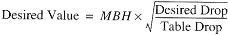
For example, if it is desired to get flow through ¾-inch (19.1 mm) pipe at 2 inches/100 feet, multiply the capacity of ¾-inch pipe at 1 inch/100 feet by the square root of the pressure ratio:
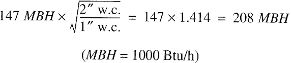
A.4 Use of sizing equations. Capacities of smooth wall pipe or tubing can also be determined by using the following formulae:
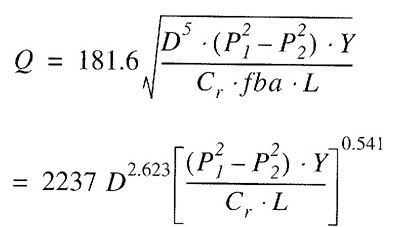
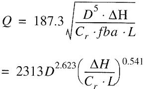
where:
Q = Rate, cubic feet per hour at 60°F and 30-inch mercury column
D = Inside diameter of pipe, in.
P1 = Upstream pressure, psia
P2 = Downstream pressure, psia
Y = Superexpansibility factor = 1/supercompressibility factor
Cr = Factor for viscosity, density and temperature*
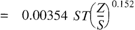
Note: See Table 402.4 for Y and Cr for natural gas and propane.
| PRESSURE DROP PER 100 FEET IN INCHES W.C. | PIPE SIZES (inch) | ||||||
| ½ | ¾ | 1 | 1¼ | 1½ | 2 | ||
| 0.2 | 31 | 64 | 121 | 248 | 372 | 716 | |
| 0.3 | 38 | 79 | 148 | 304 | 455 | 877 | |
| 0.5 | 50 | 104 | 195 | 400 | 600 | 1160 | |
| 1.0 | 71 | 147 | 276 | 566 | 848 | 1640 | |
| For SI: 1 inch = 25.4 mm. I foot = 304.8 mm. | |||||||
S - Specific gravity of gas at 60°F and 30-inch mercury column (0.60 for natural gas, 1.50 for propane), or = 1488µ
T = Absolute temperature, °F or = t + 460
t = Temperature, °F
Z = Viscosity of gas, centipoise (0.012 for natural gas, 0.008 for propane), or = 1488µ
fba = Base friction factor for air at 60°F (CF - 1)
L = Length of pipe, ft
ΔH = Pressure drop, in. w.c. (27.7 in. H20 = 1 psi)
(For SI, see Section 402.4)
A.5 Pipe and tube diameters. Where the internal diameter is determined by the formulas in Section 402.4, Tables A.5.1 and A.5.2 can be used to select the nominal or standard pipe size based on the calculated internal diameter.
| NOMINAL SIZE (inch) | INTERNAL DIAMETER (inch) |
| ¼ | 0.364 |
| 3/8 | 0.493 |
| ½ | 0.622 |
| ¾ | 0.824 |
| 1 | 1.049 |
| 1¼ | 1.380 |
| 1½ | 1.610 |
| 2 | 2.067 |
| 2½ | 2.469 |
| 3 | 3.068 |
| 3 ½ | 3.548 |
| 4 | 4.026 |
| For SI: 1 inch - 25.4 mm. | |
A.6 Use of sizing charts. A third method of sizing gas piping is detailed below as an option that is useful when large quantities of piping are involved in a job (e.g., an apartment house) and material costs are of concern. If the user is not completely familiar with this method, the resulting pipe sizing should be checked by a knowledgeable gas engineer. The sizing charts are applied as follows:
| TUBE TYPE | NOMINAL OR STANDARD SIZE (inches) | INTERNAL DIAMETER (inches) |
| K | ¼ | 0.305 |
| L | ¼ | 0.315 |
| ACR (D) | 3/8 | 0.315 |
| ACR (A) | 3/8 | 0.311 |
| K | 3/8 | 0.402 |
| L | 3/8 | 0.430 |
| ACR (D) | ½ | 0.430 |
| ACR (A) | ½ | 0.436 |
| K | ½ | 0.527 |
| ACR (D) | 5/8 | 0.545 |
| ACR (A) | 5/8 | 0.555 |
| K | 5/8 | 0.652 |
| L | 5/8 | 0.666 |
| ACR (D) | ¾ | 0.666 |
| ACR (A) | ¾ | 0.680 |
| K | ¾ | 0.745 |
| L | ¾ | 0.785 |
| ACR (D) | 7/8 | 0.785 |
| K | 1 | 0.995 |
| L | 1 | 1.025 |
| ACR | 11/8 | 1.025 |
| K | 1¼ | 1.245 |
| L | 1¼ | 1.265 |
| ACR | 13/8 | 1.265 |
| K | 1½ | 1.481 |
| L | 1½ | 1.505 |
| ACR | 15/8 | 1.505 |
| K | 2 | 1.959 |
| L | 2 | 1.985 |
| ACR | 21/8 | 1.985 |
| K | 2½ | 2.435 |
| L | 2½ | 2.465 |
| ACR | 25/8 | 2.465 |
| K | 3 | 2.907 |
| L | 3 | 2.945 |
| ACR | 31/8 | 2.945 |
| FOR SI: 1 inch = 25.4 mm. | ||
appliance. Increase this length by 50 percent to allow for fittings. Divide the allowable pressure drop by the equivalent length (in hundreds of feet) to determine the allowable pressure drop per 100 feet (30 480 mm). Select the pipe size from Figure A.6(a) for the required volume of flow.
A.7 Examples of piping system design and sizing.
A.7.1 Example 1: Longest length method. Determine the required pipe size of each section and outlet of the piping system shown in Figure A.7.1, with a designated pressure drop of 0.5-inch w.c. (125 Pa) using the Longest Length Method. The gas to be used has 0.60 specific gravity and a heating value of 1,000 Btu/ft3 (37.5 MJ/m3).
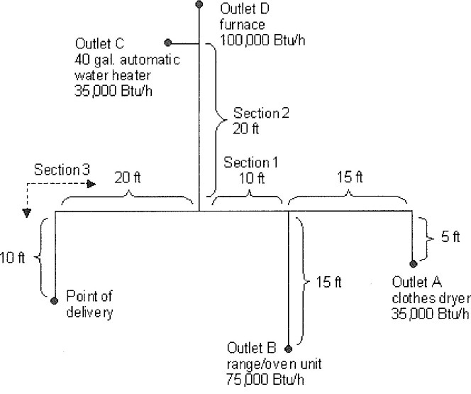
FIGURE A.7.1 PIPING PLAN SHOWING A STEEL PIPING SYSTEM
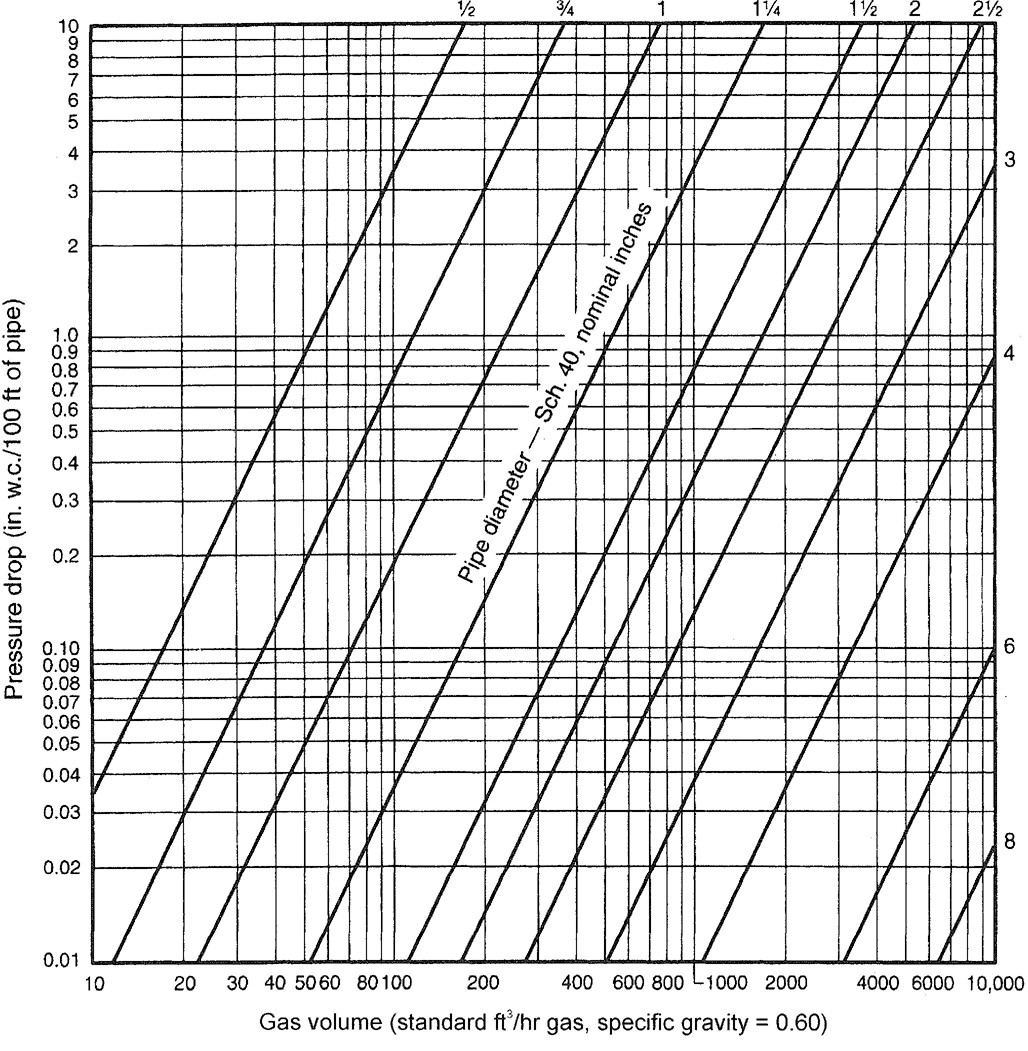
FIFURE A.6(a) CAPACITY OF NATURAL GAS PIPING, LOW PRESSURE (0.60 WC)
146Solution:
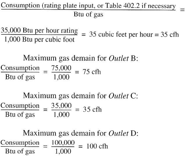
A.7.2 Example 2: Hybrid or dual pressure systems. Determine the required CSST size of each section of the piping system shown in Figure A.7.2, with a designated pressure
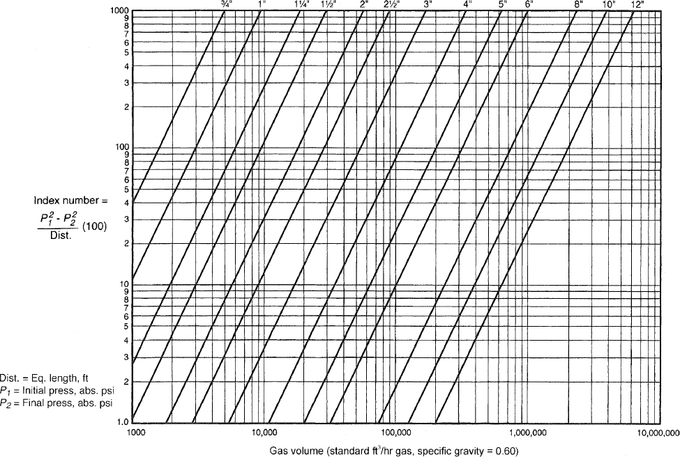
FIGURE A.6(b)
CAPACITY OF NATURAL GAS PIPING, HIGH PRESSURE(1.5 psi and above)
drop of 1 psi (6.9 kPa) for the 2 psi (13.8 kPa) section and 3-inch w.c. (0.75 kPa) pressure drop for the 13-inch w.c. (2.49 kPa) section. The gas to be used has 0.60 specific gravity and a heating value of 1,000 Btu/ft3 (37.5 MJ/m3).
Solution:
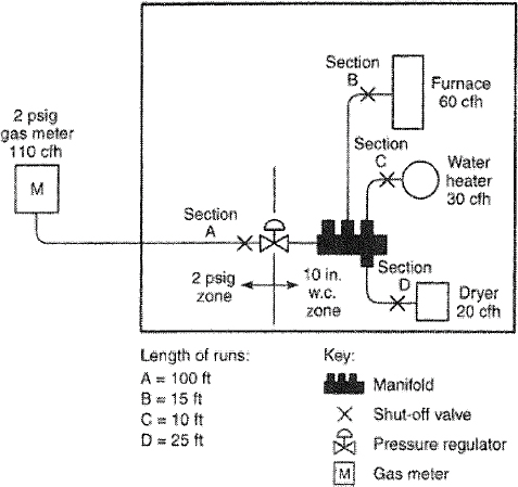
FIGURE A.7.2
PIPING PLAN SHOWING A CSST SYSTEM
Note: It is not unusual to oversize the supply line by 25 to 50 percent of the as-installed load. EHD size 18 has a capacity of 189 cfh (5.35 m3/ hr).
A.7.3 Example 3: Branch length method. Determine the required semirigid copper tubing size of each section of the piping system shown in Figure A.7.3, with a designated pressure drop of 1-inch w.c. (250 Pa) (using the Branch Length Method). The gas to be used has 0.60 specific gravity and a heating value of 1,000 Btu/ft3 (37.5 MJ/m3).
Solution:
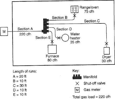
FIGURE A.7.3
PIPING PLAN SHOWING A COPPER TUBING SYSTEM
A.7.4 Example 4: Modification to existing piping system. Determine the required CSST size for Section G (retrofit application) of the piping system shown in Figure A.7.4, with a designated pressure drop of 0.5-inch w.c. (125 Pa) using the branch length method. The gas to be used has 0.60 specific gravity and a heating value of 1,000 Btu/ft3 (37.5 MJ/m3).
Solution:
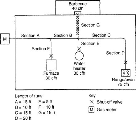
FIGURE A.7.4
PIPING PLAN SHOWING A MODIFICATION TO EXISTING PIPING SYSTEM
A.7.5 Example 5: Calculating pressure drops due to temperature changes. A test piping system is installed on a warm autumn afternoon when the temperature is 70°F (21°C). In accordance with local custom, the new piping system is subjected to an air pressure test at 20 psig (138 kPa). Overnight, the temperature drops and when the inspector shows up first thing in the morning the temperature is 40°F (4°C).
If the volume of the piping system is unchanged, then the formula based on Boyle’s and Charles’ law for determining the new pressure at a reduced temperature is as follows:

where:
T1 = Initial temperature, absolute (T1 + 459)
T2 = Final temperature, absolute (T2 + 459)
149P1 = Initial pressure, psia (P1 + 14.7)
P2 = Final pressure, psia (P2 + 14.7)
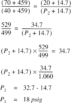
P2 = 32.7-14.7
P2 = 18 psig
Therefore, the gauge could be expected to register 18 psig (124 kPa) when the ambient temperature is 40°F (4°C).
A.7.6 Example 6: Pressure drop per 100 feet of pipe method. Using the layout shown in Figure A.7.1 and ΔH = pressure drop, in w.c. (27.7 in. H2O = 1 psi), proceed as follows:
For ½-inch pipe, ΔH = 20 feet/100 feet × 0.3 inch w.c. = 0.06 in w.c.
For ¾-inch pipe, ΔH = 15 feet/100 feet × 0.3 inch w.c. = 0.045 in w.c.
For 1 inch pipe: ΔH = 10feet/100feet× 0.2 inch w.c. = 0.02 in w.c.
For ¾-inch pipe: ΔH = 10feet/100feet × [0.5 inch w.c. + (110,000 Btu/hr-104,000 Btu/hr)/(147,000 Btu/hr-104,000 Btu/hr) × (1.0 inches w.c. - 0.5 inch w.c.)] = 0.1 × 0.57 inch w.c.≈ 0.06 inch w.c.
Note that the pressure drop between 104,000 Btu/hr and 147,000 Btu/hr has been interpolated as 110,000 Btu/hr.
For 1-inch pipe: ΔH = 20feet/10feet × [0.2 inch w.c. + (14,000 BtU/hr)/(27,000 Btu/hr) × 0.1 inch w.c.] = 0.05 inch w. c.
For ¾-inch pipe: ΔH = 20feet/100feet × 1.0 inch w.c. = 0.2 inch w.c.
Note that the pressure drop between 121,000 Btu/hr and 148,000 Btu/hr has been interpolated as 135,000 Btu/hr, but interpolation for the ¾-inch pipe (trivial for 104,000 Btu/hr to 147,000 Btu/hr) was not used.
For 1-inch pipe: ΔH = 30feet/100 feet × 1.0 inches w.c. = 0.3 inch w.c.
For l¼-inch pipe: ΔH = 30feet/100feet× 0.2 inch w.c. = 0.06 inch w.c.
Note that interpolation for these options is ignored since the table values are close to the 245,000 Btu/hr carried by that section.
Minimum pressure drop to farthest appliance:
ΔH = 0.06 inch w.c. + 0.02 inch w.c. + 0.06 inch w.c. = 0.14 inch w.c.
Larger pressure drop to the farthest appliance:
ΔH = 0.06 inch w.c. + 0.06 inch w.c. + 0.3 inch w.c. = 0.42 inch w.c.
Notice that Section 2 and the run to B do not enter into this calculation, provided that the appliances have similar input pressure requirements.
For SI units: 1 Btu/hr = 0.293 W, 1 cubic foot = 0.028 m3 1 foot = 0.305 m, 1 inch w.c. = 249 Pa.
(This appendix is informative and is not part of the code.)
Example 1: Single draft-hood-equipped appliance.
An installer has a 120,000 British thermal unit (Btu) per hour input appliance with a 5-inch-diameter draft hood outlet that needs to be vented into a 10-foot-high Type B vent system. What size vent should be used assuming (a) a 5-foot lateral single-wall metal vent connector is used with two 90-degree elbows, or (b) a 5-foot lateral single-wall metal vent connector is used with three 90-degree elbows in the vent system?
Solution:
Table 504.2(2) should be used to solve this problem, because single-wall metal vent connectors are being used with a Type B vent.
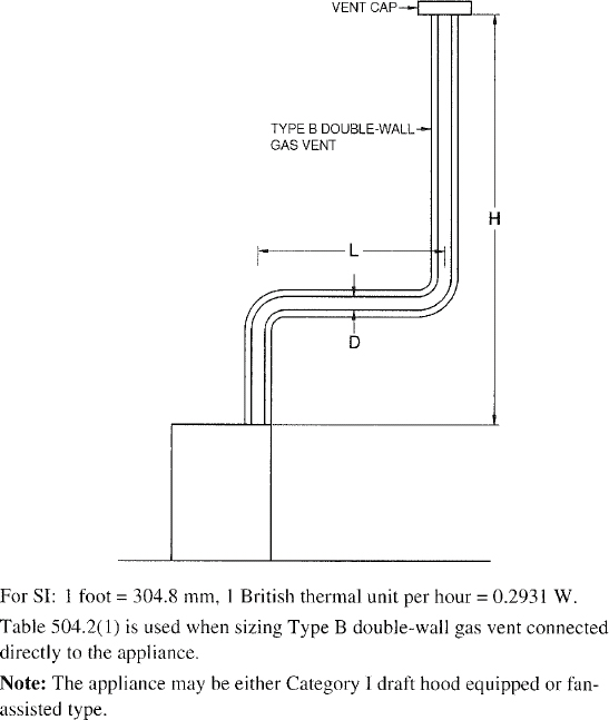
FIGURE B-1
TYPE B DOUBLE-WALL VENT SYSTEM SERVING A SINGLE APPLIANCE WITH A TYPE B DOUBLE-WALL VENT
122,000 (.90) = 110,000 for 5-inch vent From Table 504.2(2), Select 6-inch vent 186,000 (.90) = 167,000; This is greater than the required 120,000. Therefore, use a 6-inch vent and connector where three elbows are used.
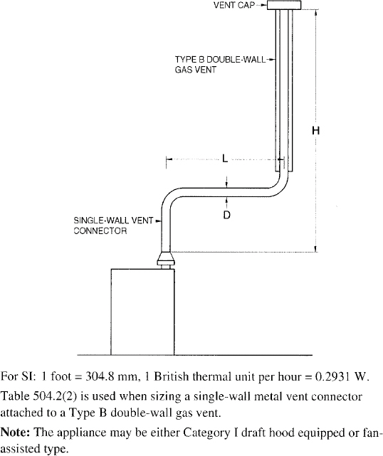
FIGURE B-2
TYPE B DOUBLE-WALL VENT SYSTEM SERVING A SINGLE APPLIANCE WITH A SINGLE-WALL METAL VENT CONNECTOR
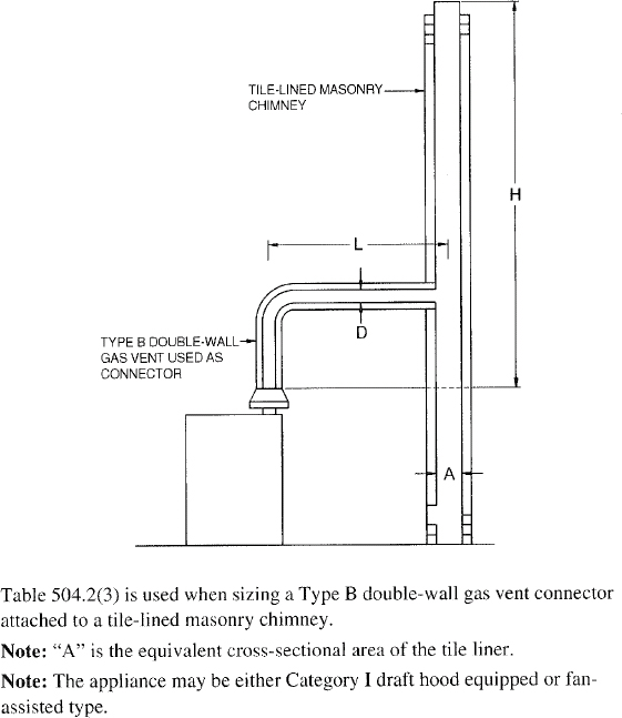
FIGURE B-3
VENT SYSTEM SERVING A SINGLE APPLIANCE WITH A MASONRY CHIMNEY OF TYPE B DOUBLE -WALL VENT CONNECTOR
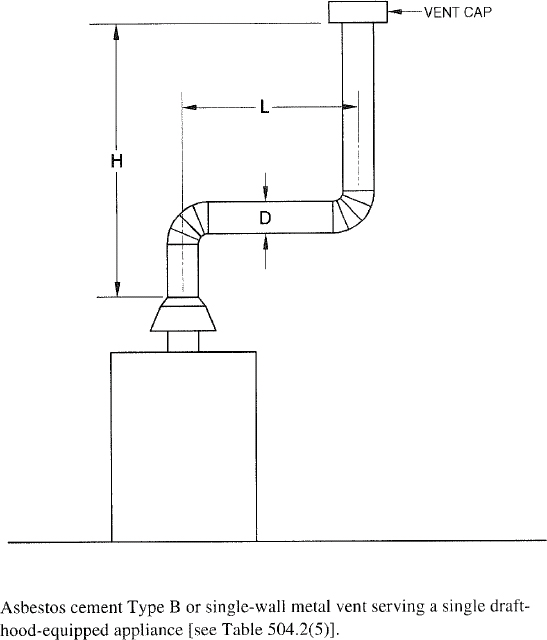
FIGURE B-4
VENT SYSTEM SERVING A SINGLE APPLIANCE USING A MASONRY CHIMNEY AND A SINGLE-WALL METAL VENT CONNECTOR
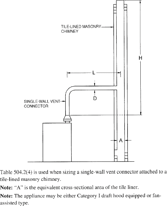
FIGURE B-5
ASBESTOS CEMENT TYPE B OR SINGLE-WALL METAL VENT SYSTEM SERVING A SINGLE DRAFT-HOOD-EQUIPPED APPLIANCE
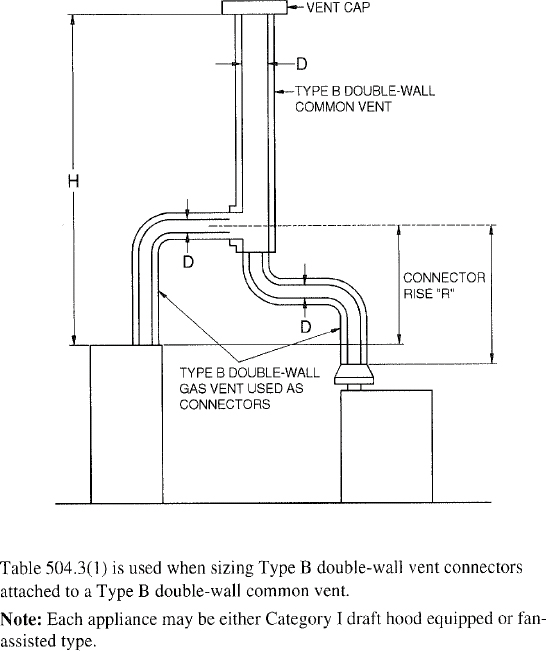
FIGURE B-6
VENT SYSTEM SERVING TWO OR MORE APPLIANCES WITH TYPE B DOUBLE-WALL VENT AND TYPE B DOUBLE-WALL VENT CONNECTOR
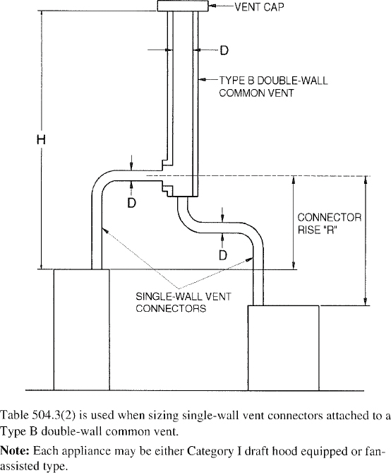
FIGURE B-7
VENT SYSTEM SERVING TWO OR MORE APPLIANCES WITH TYPE B DOUBLE-WALL VENT AND SINGLE-WALL METAL VENT CONNECTORS
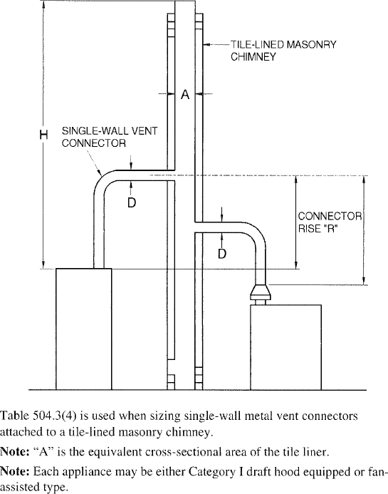
FIGURE B-8
MASONRY CHIMNEY SERVING TWO OR MORE APPLIANCES WITH TYPE B DOUBLE-WALL VENT CONNECTOR
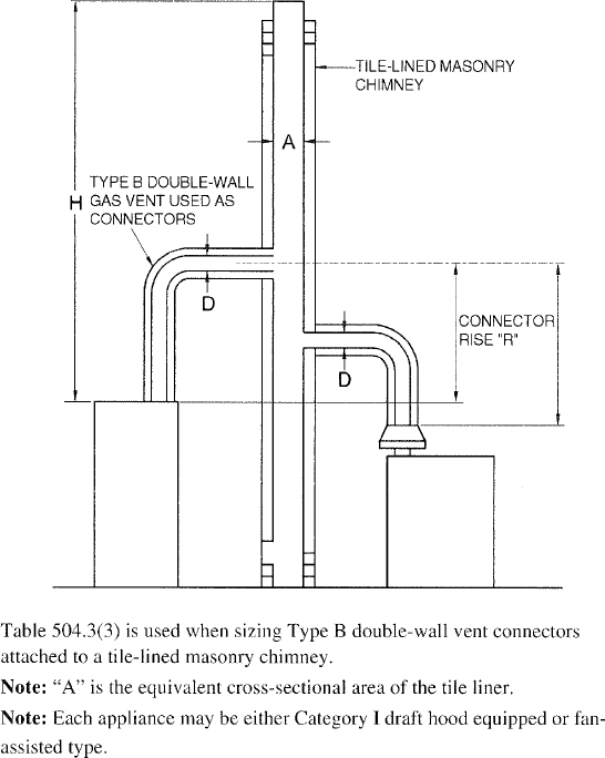
FIGURE B-9
MASONRY CHIMNEY SERVING TWO OR MORE APPLIANCES WITH SINGLE-WALL METAL VENT CONNECTORS
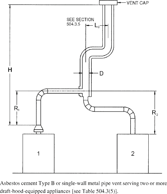
FIGURE B-10
ASBESTOS CEMENT TYPE B OR SINGLE-WALL METAL VENT SYSTEM SERVING TWO OR MORE DRAFT-HOOD-EQUIPPED APPLIANCES

FIGURE B-11
USE OF MANIFOLD COMMON VENT CONNECTOR
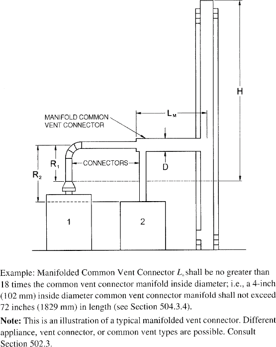
FIGURE B-12
USE OF OFFSET COMMON VENT
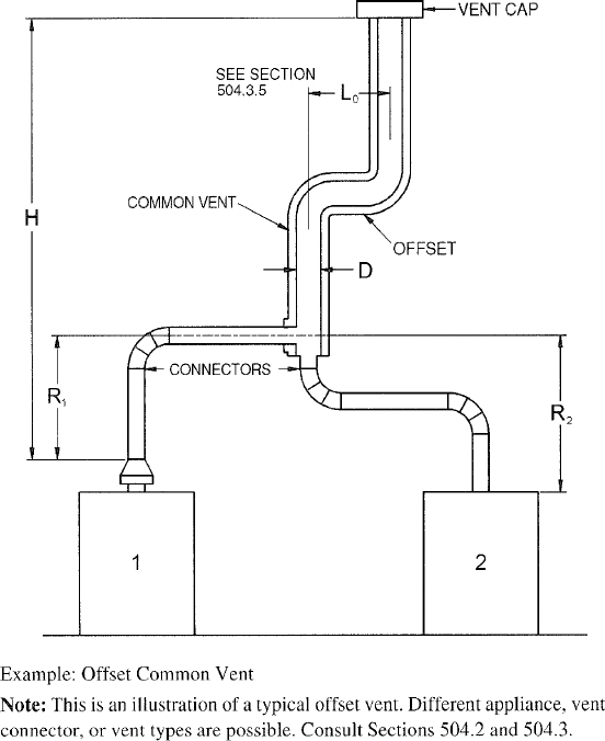
FIGURE B-13
MULTISTORY GAS VENT DESIGN PROCEDURE FOR EACH SEGMENT OF SYSTEM
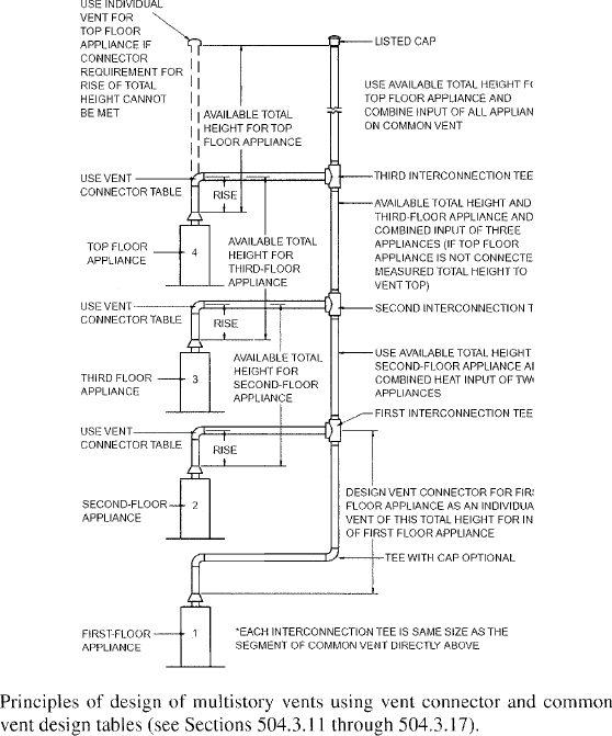
FIGURE B-14
MULTISTROY VENT SYSTEMS
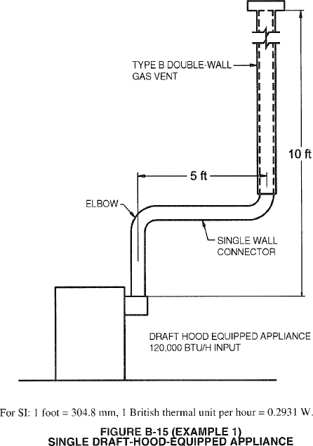
FIGURE B-15 (EXAMPLE 1)
SINGLE DRAFT-HOOD-EQUIPPED APPLIANCE
Example 2: Single fan-assisted appliance.
An installer has an 80,000 Btu per hour input fan-assisted appliance that must be installed using 10 feet of lateral connector attached to a 30-foot-high Type B vent. Two 90-degree elbows are needed for the installation. Can a single-wall metal vent connector be used for this application?
Solution:
Table 504.2(2) refers to the use of single-wall metal vent connectors with Type B vent. In the first column find the row associated with a 30-foot height and a 10-foot lateral. Read across this row, looking at the FAN Min and FAN Max columns, to find that a 3-inch-diameter single-wall metal vent connector is not recommended. Moving to the next larger size single wall connector (4 inches), note that a 4-inch-diameter single-wall metal connector has a recommended minimum vent capacity of 91,000 Btu per hour and a recommended maximum vent capacity of 144,000 Btu per hour. The 80,000 Btu per hour fan-assisted appliance is outside this range, so the conclusion is that a single-wall metal vent connector cannot be used to vent this appliance using 10 feet of lateral for the connector.
However, if the 80,000 Btu per hour input appliance could be moved to within 5 feet of the vertical vent, then a 4-inch single-wall metal connector could be used to vent the appliance. Table 504.2(2) shows the acceptable range of vent capacities for a 4-inch vent with 5 feet of lateral to be between 72,000 Btu per hour and 157,000 Btu per hour.
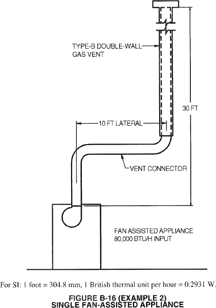
FIGURE B-16 (EXAMPLE 2)
SINGLE FAN-ASSISTED APPLIANCE
If the appliance cannot be moved closer to the vertical vent, then Type B vent could be used as the connector material. In this case, Table 504.2(1) shows that for a 30-foot-high vent with 10 feet of lateral, the acceptable range of vent capacities for a 4-inch-diameter vent attached to a fan-assisted appliance is between 37,000 Btu per hour and 150,000 Btu per hour.
Example 3: Interpolating between table values.
An installer has an 80,000 Btu per hour input appliance with a 4-inch-diameter draft hood outlet that needs to be vented into a 12-foot-high Type B vent. The vent connector has a 5-foot lateral length and is also Type B. Can this appliance be vented using a 4-inch-diameter vent?
Solution:
Table 504.2(1) is used in the case of an all Type B vent system. However, since there is no entry in Table 504.2(1) for a height of 12 feet, interpolation must be used. Read down the 4- inch diameter NAT Max column to the row associated with 10-foot height and 5-foot lateral to find the capacity value of 77,000 Btu per hour. Read further down to the 15-foot height, 5- foot lateral row to find the capacity value of 87,000 Btu per hour. The difference between the 15-foot height capacity value and the 10-foot height capacity value is 10,000 Btu per hour. The capacity for a vent system with a 12-foot height is equal to the capacity for a 10-foot height plus2/5 of the difference between the 10-foot and 15-foot height values, or 77,000 +2/5 (10,000) = 81,000 Btu per hour. Therefore, a 4-inch-diameter vent may be used in the installation.
155EXAMPLES USING COMMON VENTING TABLES
Example 4: Common venting two draft-hood-equipped appliances.
A 35,000 Btu per hour water heater is to be common vented with a 150,000 Btu per hour furnace using a common vent with a total height of 30 feet. The connector rise is 2 feet for the water heater with a horizontal length of 4 feet. The connector rise for the furnace is 3 feet with a horizontal length of 8 feet. Assume single-wall metal connectors will be used with Type B vent. What size connectors and combined vent should be used in this installation?
Solution:
Table 504.3(2) should be used to size single-wall metal vent connectors attached to Type B vertical vents. In the vent connector capacity portion of Table 504.3(2), find the row associated with a 30-foot vent height. For a 2-foot rise on the vent connector for the water heater, read the shaded columns for draft-hood-equipped appliances to find that a 3-inch-diameter vent connector has a capacity of 37,000 Btu per hour. Therefore, a 3-inch single-wall metal vent connector may be used with the water heater. For a draft-hood-equipped furnace with a 3-foot rise, read across the appropriate row to find that a 5-inch-diameter vent connector has a maximum capacity of 120,000 Btu per hour (which is too small for the furnace) and a 6-inch-diameter vent connector has a maximum vent capacity of 172,000 Btu per hour. Therefore, a 6-inch-diameter vent connector should be used with the 150,000 Btu per hour furnace. Since both vent connector horizontal lengths are less than the maximum lengths listed in Section 504.3.2, the table values may be used without adjustments.
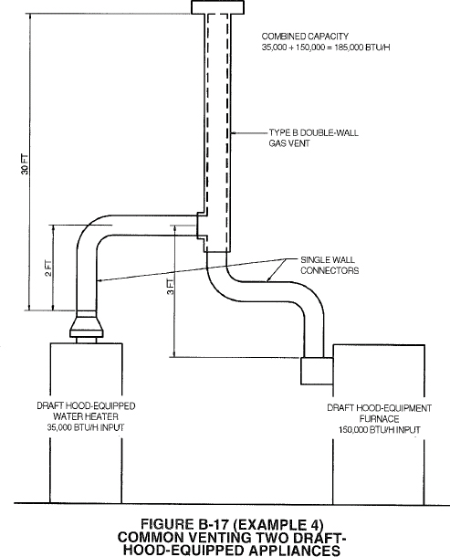
FIGURE B-17 (EXAMPLE 4)
COMMON VENTING TWO DRAFT-HOOD-EQUIPPED APPLIANCES
In the common vent capacity portion of Table 504.3(2), find the row associated with a 30-foot vent height and read over to the NAT + NAT portion of the 6-inch-diameter column to find a maximum combined capacity of 257,000 Btu per hour. Since the two appliances total only 185,000 Btu per hour, a 6-inch common vent may be used.
Example 5a: Common venting a draft-hood-equipped water heater with a fan-assisted furnace into a Type B vent.
In this case, a 35,000 Btu per hour input draft-hood-equipped water heater with a 4-inch-diameter draft hood outlet, 2 feet of connector rise, and 4 feet of horizontal length is to be common vented with a 100,000 Btu per hour fan-assisted furnace with a 4-inch-diameter flue collar, 3 feet of connector rise, and 6 feet of horizontal length. The common vent consists of a 30-foot height of Type B vent. What are the recommended vent diameters for each connector and the common vent? The installer would like to use a single-wall metal vent connector.
Solution: [Table 504.3(2)].
Water Heater Vent Connector Diameter. Since the water heater vent connector horizontal length of 4 feet is less than the maximum value listed in Section 504.3.2, the venting table values may be used without adjustments. Using the Vent Connector Capacity portion of Table 504.3(2), read down the Total Vent Height (H) column to 30 feet and read across the 2-foot Connector Rise (R) row to the first Btu per hour rating in the NAT Max column that is equal to or greater than the water heater input rating. The table shows that a 3-inch vent connector has a maximum input rating of 37,000
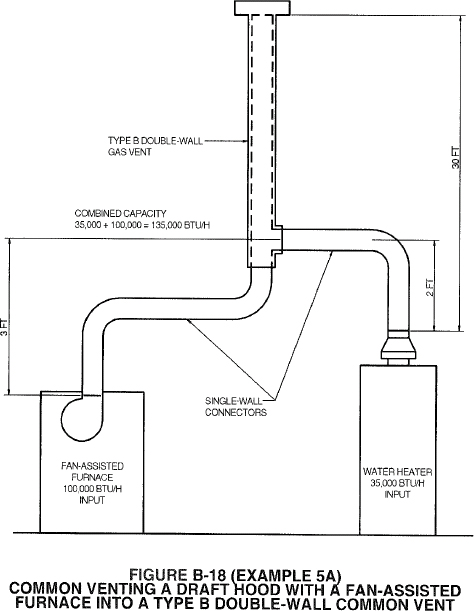
FIGURE B-18 (EXAMPLE 5A)
COMMON VENTING A DRAFT HOOD WITH A FAN-ASSISTED FURNACE INTO A TYPE B DOUBLE-WALL COMMON VENT
Btu per hour. Although this is greater than the water heater input rating, a 3-inch vent connector is prohibited by Section 504.3.21. A 4-inch vent connector has a maximum input rating of 67,000 Btu per hour and is equal to the draft hood outlet diameter. A 4-inch vent connector is selected. Since the water heater is equipped with a draft hood, there are no minimum input rating restrictions.
Furnace Vent Connector Diameter. Using the Vent Connector Capacity portion of Table 504.3(2), read down the Total Vent Height (H) column to 30 feet and across the 3-foot Connector Rise (R) row. Since the furnace has a fan-assisted combustion system, find the first FAN Max column with a Btu per hour rating greater than the furnace input rating. The 4-inch vent connector has a maximum input rating of 119,000 Btu per hour and a minimum input rating of 85,000 Btu per hour. The 100,000 Btu per hour furnace in this example falls within this range, so a 4-inch connector is adequate. Since the furnace vent connector horizontal length of 6 feet does not exceed the maximum value listed in Section 504.3.2, the venting table values may be used without adjustment. If the furnace had an input rating of 80,000 Btu per hour, then a Type B vent connector [see Table 504.3(1)] would be needed in order to meet the minimum capacity limit.
Common Vent Diameter. The total input to the common vent is 135,000 Btu per hour. Using the Common Vent Capacity portion of Table 504.3(2), read down the Total Vent Height (H) column to 30 feet and across this row to find the smallest vent diameter in the FAN + NAT column that has a Btu per hour rating equal to or greater than 135,000 Btu per hour. The 4-inch common vent has a capacity of 132,000 Btu per hour and the 5-inch common vent has a capacity of 202,000 Btu per hour. Therefore, the 5-inch common vent should be used in this example.
Summary. In this example, the installer may use a 4-inch-diameter, single-wall metal vent connector for the water heater and a 4-inch-diameter, single-wall metal vent connector for the furnace. The common vent should be a 5-inch-diameter Type B vent.
In this case, the water heater and fan-assisted furnace of Example 5a are to be common vented into a clay tile-lined masonry chimney with a 30-foot height. The chimney is not exposed to the outdoors below the roof line. The internal dimensions of the clay tile liner are nominally 8 inches by 12 inches. Assuming the same vent connector heights, laterals, and materials found in Example 5a, what are the recommended vent connector diameters, and is this an acceptable installation?
Solution:
Table 504.3(4) is used to size common venting installations involving single-wall connectors into masonry chimneys.
Water Heater Vent Connector Diameter. Using Table 504.3(4), Vent Connector Capacity, read down the Total Vent Height (H) column to 30 feet, and read across the 2-foot Connector Rise (R) row to the first Btu per hour rating in the NAT Max column that is equal to or greater than the water heater input rating. The table shows that a 3-inch vent connector has a maximum input of only 31,000 Btu per hour while a 4-inch vent connector has a maximum input of 57,000 Btu per hour. A 4-inch vent connector must therefore be used.
Furnace Vent Connector Diameter. Using the Vent Connector Capacity portion of Table 504.3(4), read down the Total Vent Height (H) column to 30 feet and across the 3-foot Connector Rise (R) row. Since the furnace has a fan-assisted combustion system, find the first FAN Max column with a Btu per hour rating greater than the furnace input rating. The 4-inch vent connector has a maximum input rating of 127,000 Btu per hour and a minimum input rating of 95,000 Btu per hour. The 100,000 Btu per hour furnace in this example falls within this range, so a 4-inch connector is adequate.
Masonry Chimney. From Table B-l, the equivalent area for a nominal liner size of 8 inches by 12 inches is 63.6 square inches. Using Table 504.3(4), Common Vent Capacity, read down the FAN + NAT column under the Minimum Internal Area of Chimney value of 63 to the row for 30-foot height to find a capacity value of 739,000 Btu per hour. The combined input rating of the furnace and water heater, 135,000 Btu per hour, is less than the table value, so this is an acceptable installation.
Section 504.3.17 requires the common vent area to be no greater than seven times the smallest listed appliance categorized vent area, flue collar area, or draft hood outlet area. Both appliances in this installation have 4-inch-diameter outlets. From Table B-l, the equivalent area for an inside diameter of 4 inches is 12.2 square inches. Seven times 12.2 equals 85.4, which is greater than 63.6, so this configuration is acceptable.
In this case, the water heater and fan-assisted furnace of Examples 5a and 5b are to be common vented into an exterior masonry chimney. The chimney height, clay tile liner dimensions, and vent connector heights and laterals are the same as in Example 5b. This system is being installed in Charlotte, North Carolina. Does this exterior masonry chimney need to be relined? If so, what corrugated metallic liner size is recommended? What vent connector diameters are recommended?
Solution:
According to Section 504.3.20, Type B vent connectors are required to be used with exterior masonry chimneys. Use Tables 504.3(7a), (7b) to size FAN+NAT common venting installations involving Type-B double wall connectors into exterior masonry chimneys.
The local 99-percent winter design temperature needed to use Table 504.3(7b) can be found in the ASHRAE Handbook of Fundamentals. For Charlotte, North Carolina, this design temperature is 19˚F.
Chimney Liner Requirement. As in Example 5b, use the 63 square inch Internal Area columns for this size clay tile liner. Read down the 63 square inch column of Table 504.3(7a) to the 30-foot height row to find that the combined appliance maximum input is 747,000 Btu per hour. The combined input rating of the appliances in this installation, 135,000 Btu per hour, is less than the maximum value, so this
157criterion is satisfied. Table 504.3(7b), at a 19˚F design temperature, and at the same vent height and internal area used above, shows that the minimum allowable input rating of a space-heating appliance is 470,000 Btu per hour. The furnace input rating of 100,000 Btu per hour is less than this minimum value. So this criterion is not satisfied, and an alternative venting design needs to be used, such as a Type B vent shown in Example 5a or a listed chimney liner system shown in the remainder of the example.
According to Section 504.3.19, Table 504.3(1) or 504.3(2) is used for sizing corrugated metallic liners in masonry chimneys, with the maximum common vent capacities reduced by 20 percent. This example will be continued assuming Type B vent connectors.
Water Heater Vent Connector Diameter. Using Table 504.3(1), Vent Connector Capacity, read down the Total Vent Height (H) column to 30 feet, and read across the 2-foot Connector Rise (R) row to the first Btu/h rating in the NAT Max column that is equal to or greater than the water heater input rating. The table shows that a 3-inch vent connector has a maximum capacity of 39,000 Btu/h. Although this rating is greater than the water heater input rating, a 3-inch vent connector is prohibited by Section 504.3.21. A 4-inch vent connector has a maximum input rating of 70,000 Btu/h and is equal to the draft hood outlet diameter. A 4-inch vent connector is selected.
Furnace Vent Connector Diameter. Using Table 504.3(1), Vent Connector Capacity, read down the Vent Height (H) column to 30 feet, and read across the 3-foot Connector Rise (R) row to the first Btu per hour rating in the FAN Max column that is equal to or greater than the furnace input rating. The 100,000 Btu per hour furnace in this example falls within this range, so a 4-inch connector is adequate.
Chimney Liner Diameter. The total input to the common vent is 135,000 Btu per hour. Using the Common Vent Capacity Portion of Table 504.3(1), read down the Vent Height (H) column to 30 feet and across this row to find the smallest vent diameter in the FAN+NAT column that has a Btu per hour rating greater than 135,000 Btu per hour. The 4-inch common vent has a capacity of 138,000 Btu per hour. Reducing the maximum capacity by 20 percent (Section 504.3.19) results in a maximum capacity for a 4-inch corrugated liner of 110,000 Btu per hour, less than the total input of 135,000 Btu per hour. So a larger liner is needed. The 5-inch common vent capacity listed in Table 504.3(1) is 210,000 Btu per hour, and after reducing by 20 percent is 168,000 Btu per hour. Therefore, a 5-inch corrugated metal liner should be used in this example.
Single-Wall Connectors. Once it has been established that relining the chimney is necessary, Type B double-wall vent connectors are not specifically required. This example could be redone using Table 504.3(2) for single-wall vent connectors. For this case, the vent connector and liner diameters would be the same as found above with Type B double-wall connectors.
| NOMINAL LINER SIZE (inches) | INSIDE DIMENSIONS OF LINER (inches) | INSIDE DIAMETER OR EQUIVALENT DIAMETER (inches) | EQUIVALENT AREA (square inches) |
|---|---|---|---|
| 4 × 8 | 2½ × 6½ | 4 | 12.2 |
| 5 | 19.6 | ||
| 6 | 28.3 | ||
| 7 | 38.3 | ||
| 8 × 8 | 6¾ × 6¾ | 7.4 | 42.7 |
| 8 | 50.3 | ||
| 8 × 12 | 6½ × 10½ | 9 | 63.6 |
| 10 | 78.5 | ||
| 12 × 12 | 9¾ × 9¾ | 10.4 | 83.3 |
| 11 | 95 | ||
| 12 × 16 | 9½ × 13½ | 11.8 | 107.5 |
| 12 | 113.0 | ||
| 14 | 153.9 | ||
| 16 × 16 | 13¼ × 13¼ | 14.5 | 162.9 |
| 15 | 176.7 | ||
| 16 × 20 | 13 × 17 | 16.2 | 206.1 |
| 18 | 254.4 | ||
| 20 × 20 | 16¾ × 16¾ | 18.2 | 260.2 |
| 20 | 314.1 | ||
| 20 × 24 | 16½ × 20½ | 20.1 | 314.1 |
| 22× | 380.1 | ||
| 24 × 24 | 20¼ × 20¼ | 22.1 | 380.1 |
| 24 | 452.3 | ||
| 24 × 28 | 20¼ × 20¼ | 24.1 | 456.2 |
| 28 × 28 | 24¼ × 24¼ | 26.4 | 543.3 |
| 27 | 572.5 | ||
| 30 × 30 | 25½ × 25½ | 27.9 | 607 |
| 30 | 706.8 | ||
| 30 × 36 | 25½ × 31½ | 30.9 | 749.9 |
| 33 | 855.3 | ||
| 36 × 36 | 31½ × 31½ | 34.4 | 929.4 |
| 36 | 1017.9 | ||
| For SI: 1 inch = 25.4 mm, 1 square inch = 645.16 m2. | |||
| a. Where liner sizes differ dimensionally from those shown in Table B-l, equivalent diameters may be determined from published tables for square and rectangular ducts of equivalent carrying capacity or by other engineering methods. | |||
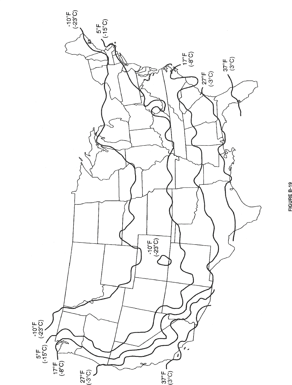
FIGURE B-19
159 160>(This appendix is informative and is not part of the code.)
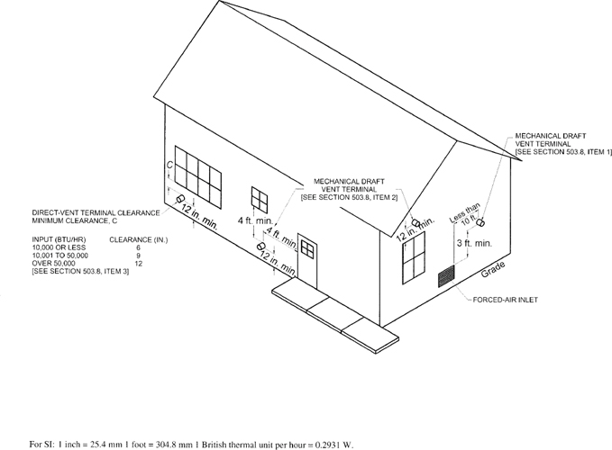
APPENDIX C
EXIT TERMINALS OF MECHANICAL DRAFT AND DIRECT-VENT VENTING SYSTEMS
(This appendix is informative and is not part of the code.)
The following procedure is intended as a guide to aid in determining that an appliance is properly installed and is in a safe condition for continuing use.
This procedure is intended for cental furnace and boiler installations and may not be applicable to all installations.
| A | ||
| ACCESS, APPLIANCES | ||
| General | 306 | |
| Shutoff valves | 409.1.3, 409.3.1, 409.5 | |
| Wall furnaces, vented | 608.6 | |
| AIR HEATERS, DIRECT-FIRED | 611,612 | |
| Industrial | 611, 612 | |
| Venting | 501.8 | |
| AIR, COMBUSTION | ||
| Defined | 202 | |
| Requirements | 304 | |
| AIR-CONDITIONING EQUIPMENT | 627 | |
| Clearances | 308.3 | |
| ALTERNATE MATERIALS AND METHODS | 105.2 | |
| APPLIANCES | ||
| Broilers for indoor use | 623.5 | |
| Connections to building piping | 411 | |
| Cooking | 623 | |
| Decorative | 602 | |
| Decorative vented | 202, 303.3, Table 503.4, 604 | |
| Domestic cooking. | 623.3 | |
| Electrical | 309 | |
| General | Chapter 6 | |
| Installation | Chapter 6 | |
| Listing | 301.3 | |
| Prohibited locations | 303.3, 623.2 | |
| Protection from vehicle impact | 303.4 | |
| B | ||
| BENDS, PIPE. | 405 | |
| BOILERS | ||
| Existing installations | Appendix D | |
| Listed | 631 | |
| Prohibited locations | 303.3 | |
| Unlisted | 632 | |
| BONDING | 310 | |
| BUSHINGS. | 403.10.4, 404.5 | |
| C | ||
| CENTRAL FURNACES | ||
| Clearances | 308.4 | |
| Defined | 202 | |
| Drain pans | 307.5 | |
| Existing installation | Appendix D | |
| CERTIFICATES | 104.7 | |
| CERTIFICATION | 401.10 | |
| CHIMNEYS | Chapter 5 | |
| Alternate methods of sizing | 503.5.5 | |
| Clearance reduction | 308 | |
| Defined | 202 | |
| Existing | 501.15, 503.5.6.1 | |
| Masonry | 501.3 | |
| CLEARANCE REDUCTION | 308 | |
| CLEARANCES | ||
| Air-conditioning appliances | 627.4 | |
| Boilers | 308.4 | |
| Chimney | 501.15.4 | |
| Clearance reduction | 308 | |
| Vent connectors | 503.10.5 | |
| CLOTHES DRYERS | ||
| Defined | 202 | |
| Exhaust | 614 | |
| General | 613 | |
| CODE OFFICIAL | ||
| Defined | 202 | |
| Duties and powers | 104 | |
| COMBUSTION AIR | ||
| Combination indoor and outdoor | 304.7 | |
| Defined | 202 | |
| Ducts | 304.11 | |
| Free area of openings | 304.5.3.1, 304.5.3.2, 304.6.1, 304.6.2, 304.7, 304.10 | |
| Fumes and gases | 304.12 | |
| Indoor | 304.5 | |
| Makeup air | 304.4 | |
| Mechanical supply | 304.9 | |
| Openings connecting spaces | 304.5.3 | |
| Outdoor | 304.6 | |
| COMPRESSED NATURAL GAS | 413 | |
| CONCEALED PIPING | 404.5 | |
| CONDENSATE DISPOSAL | 307 | |
| CONTROLS | ||
| Boilers | 631.2 | |
| Gas pressure regulators | 410, 628.4 | |
| CONVERSION BURNERS | 619 | |
| COOKING APPLIANCES | 623 | |
| CORROSION PROTECTION | 404.11 | |
| CREMATORIES | 606 | |
| CUTTING, NOTCHING AND BORED HOLES | 302.3 165 | |
| D | ||
| DAMPERS, VENT | 503.14, 503.15, 504.2.1, 504.3.1 | |
| DECORATIVE APPLIANCES | 602, 604 | |
| DECORATIVE SHROUDS | 503.5.4, 503.6.4.1 | |
| DEFINITIONS | Chapter 2 | |
| DIRECT VENT APPLIANCES | ||
| Defined | 202 | |
| Installation | 304.1, 503.2.3 | |
| DIVERSITY FACTOR | 402.2, Appendix A | |
| DRAFT HOODS | 202, 503.12 | |
| DUCT FURNACES | 202, 610 | |
| E | ||
| ELECTRICAL BONDING | 310 | |
| ELECTRICAL CONNECTIONS | 309.2 | |
| EXHAUST INTERLOCK | 505.1.1 | |
| EXHAUST SYSTEMS | 202, 503.2.1, 503.3.4, 505.1.1 | |
| EXCESS FLOW VALVES | 410.4 | |
| F | ||
| FEES | 106.5, 106.6 | |
| FLASHBACK ARRESTOR | 410.4 | |
| FLOOD HAZARD | 301.11 | |
| FLOOR FURNACES | 609 | |
| FURNACES | ||
| Central heating, clearance | 308.3, 308.4 | |
| Duct | 610 | |
| Floor | 609 | |
| Prohibited location | 303.3 | |
| Vented wall | 608 | |
| Warm-air | 618 | |
| G | ||
| GARAGE, INSTALLATION | 305.3, 305.4, 305.5, 305.9, 305.10 | |
| GASEOUS HYDROGEN SYSTEMS | 635, Chapter 7 | |
| General requirements | 703 | |
| Piping, use and handling | 704 | |
| Testing | 705 | |
| GROUNDING, ELECTRODE | 309.1 | |
| H | ||
| HISTORIC BUILDINGS | 102.6 | |
| HOT PLATES AND LAUNDRY STOVES | 501.8, 623.1 | |
| I | ||
| ILLUMINATING APPLIANCES | 628 | |
| INCINERATORS | 503.2.5, 606, 607 | |
| INFRARED RADIANT HEATERS | 411.3, 630 | |
| INSPECTIONS | 104.4, 107 | |
| INSTALLATION, APPLIANCES | ||
| Garage | 305.3, 305.3.1, 305.3.2, 305.4, 305.5, 305.9, 305.10 | |
| General | 305 | |
| Listed and unlisted appliances | 301.3, 305.1 | |
| Specific appliances | Chapter 6 | |
| K | ||
| KILNS | 629 | |
| L | ||
| LIQUEFIED PETROLEUM GAS | ||
| Defined | 202 | |
| Motor vehicle fuel-dispensing stations | 412 | |
| Piping material | 403.6.2, 403.11 | |
| Size of pipe or tubing | Appendix A | |
| Storage | 401.2 | |
| Systems | 402.6.1 | |
| Thread compounds | 403.9.3 | |
| LISTED AND LABELED APPLIANCES | 301.3 | |
| LOG LIGHTERS | 603 | |
| M | ||
| MANUFACTURED HOME CONNECTIONS | 411 | |
| MATERIALS, DEFECTIVE | ||
| Repair | 301.9 | |
| Workmanship and defects | 403.7 | |
| METERS | ||
| Identification | 401.7 | |
| Interconnections | 401.6 | |
| Multiple installations | 401.7 | |
| MINIMUM SAFE PERFORMANCE, VENT SYSTEMS | 503.3, 503.3.1, 503.3.2 | |
| O | ||
| OUTLET CLOSURES | 404.15 | |
| Outlet location | 404.16 | |
| OVERPRESSURE PROTECTION | 416 | |
| OXYGEN DEPLETION SAFETY SYSTEM | ||
| Defined | 202 | |
| Unvented room heaters | 303.3(3), 303.3(4), 621.6 166 | |
| P | ||
| PIPE SIZING | 402 | |
| PIPING | ||
| Bends | 405 | |
| Bonding | 310 | |
| Changes in direction | 405 | |
| Concealed locations | 404.5 | |
| Identification | 401.5 | |
| Installation | 404 | |
| Inspection | 406 | |
| Materials | 403 | |
| Maximum pressure | 402.6 | |
| Plastic | 403.6, 403.6.3, 403.11, 404.17 | |
| Prohibited penetrations and locations | 404.3, 404.6 | |
| Purging | 406.7 | |
| Sediment traps | 408.4 | |
| Sizing | 402 | |
| Support | 407, 415 | |
| Testing | 406 | |
| Tracer wire | 404.17.3 | |
| POOL HEATERS | 617 | |
| POWERS AND DUTIES OF THE CODE OFFICIAL | 104 | |
| PRESSURE DROP | 402.5 | |
| PROHIBITED INSTALLATIONS | ||
| Elevator shafts | 301.15 | |
| Floor furnaces | 609.2 | |
| Fuel-burning appliances | 303.3 | |
| Piping in partitions | 404.4 | |
| Plastic piping | 404.17 | |
| Unvented room heater | 621.2, 621.4 | |
| PURGING | 406.7 | |
| R | ||
| RADIANT HEATERS | 630 | |
| RANGES, DOMESTIC | 623.3 | |
| REFRIGERATORS | 501.8, 625 | |
| REGULATORS, PRESSURE | 410, 628.4 | |
| RISERS, ANODELESS | 403.6.1 | |
| ROOFTOP INSTALLATIONS | 306.5 | |
| ROOM HEATERS | ||
| Defined | 202 | |
| Location | 303.3 | |
| Unvented | 621 | |
| Vented | 622 | |
| S | ||
| SAFETY SHUTOFF DEVICES | ||
| Flame safeguard device | 602.2 | |
| Unvented room heaters | 621.6 | |
| SAUNA HEATERS | 615 | |
| SCOPE | 101.2 | |
| SCOPE AND ADMINISTRATION | Chapter 1 | |
| Alternate materials and methods | 105.2 | |
| Appeals | 109 | |
| Certificates | 104.7 | |
| Conflicts | 102.1 | |
| Connection of utilities | 107.6 | |
| Construction documents | 106.3.1 | |
| Duties and powers of code official | 104 | |
| Fees | 106.5, 106.6 | |
| Inspections and testing | 104.4, 106.4, 107 | |
| Liability | 103.4 | |
| Modifications | 105.1 | |
| Permits | 106 | |
| Referenced codes and standards | 102.8 | |
| Requirements not covered by code | 102.9 | |
| Severability | 101.5 | |
| Scope | 101.2 | |
| Temporary equipment | 110 | |
| Title | 101.1 | |
| Violations and penalties | 108 | |
| SEDIMENT TRAP | 408.4 | |
| SEISMIC RESISTANCE | 301.12 | |
| SERVICE SPACE | 306 | |
| SHUTOFF VALVES | 409 | |
| SPA HEATERS | 617 | |
| STANDARDS | Chapter 8 | |
| STRUCTURAL SAFETY | 302 | |
| SUPPORTS, PIPING | 407,415 | |
| T | ||
| TEMPORARY EQUIPMENT | 110 | |
| TESTING | 107 | |
| THIMBLE, VENT | 503.7.7, 503.10.11 | |
| THREADS | ||
| Damaged | 403.9.1 | |
| Specifications | 403.9 | |
| TOILETS, GAS-FIRED | 626 | |
| TUBING JOINTS | 403.10.2 167 | |
| U | ||
| UNIT HEATERS | 620 | |
| UNLISTED BOILERS | 632 | |
| UNSAFE CHIMNEYS | 503.5.6.3 | |
| UNVENTED ROOM HEATERS | 621 | |
| UNDERGROUND PENETRATIONS | 404.6 | |
| V | ||
| VALIDITY | 106.5.2 | |
| VALVES, MULTIPLE HOUSE LINES | 409.3 | |
| VALVES, SHUTOFF | Appliances 409.5 | |
| VENTED DECORATIVE APPLIANCES | 604 | |
| VENTED ROOM HEATERS | 622 | |
| VENTED WALL FURNACES | 608 | |
| VENTILATING HOODS | 503.2.1 ,503.3.4, 505.1.1 | |
| VENTS | ||
| Appliances not requiring vents | 501.8 | |
| Caps | 503.6.6 | |
| Direct vent | 503.2.3 | |
| Exhaust hoods | 505.1.1, 503.3.4 | |
| Gas vent termination | 503.6.4 | |
| General | Chapter 5 | |
| Integral | 505 | |
| Listed and labeled | 502.1 | |
| Mechanical vent | 505 | |
| Plastic pipe | 503.4.1 | |
| Wall penetrations | 503.16 | |
| VENT, SIZING | ||
| Category I appliances | 502, 503, 504 | |
| Multi-appliance | 504.3 | |
| Multistory | 504.3.13, 504.3.14, 504.3.15, 504.3.16 | |
| Single appliance | 504.2 | |
| VIOLATIONS AND PENALTIES | 108 | |
| W | ||
| WALL FURNACES, VENTED | 608 | |
| WARM AIR FURNACES | 618 | |
| WATER HEATERS | 624 | |
| WIND RESISTANCE | 301.10 | |