California Code of Regulations
Title 24, Part 6
California Building
Standards Commission
California Code of Regulations
Title 24, Part 6
California Building
Standards Commission

EFFECTIVE DATE: January 1, 2011
(For Errata and supplements, See History Note Appendix)
Public Domain: U.S. Court of Appeals, Fifth Circuit, 99-40632
2010 California Energy Code
California Code of Regulations, Title 24, Part 6
First Printing: March 2010
ISBN 978-1-58001-976-7
Published by
International Code Council
500 New Jersey Avenue, NW, 6th Floor
Washington, D.C. 20001
1-888-422-7233
COPYRIGHT © 2010
held by
California Building Standards Commission
2525 Natomas Park Drive, Suite 130
Sacramento, California 95833-2936
PRINTED IN THE U.S.A.
This document is the 6th of 12 parts of the official triennial compilation and publication of the adoptions, amendments and repeal of administrative regulations to California Code of Regulations, Title 24, also referred to as the California Building Standards Code. This part is known as the California Energy Code.
The California Building Standards Code is published in its entirety every three years by order of the California legislature, with supplements published in intervening years. The California legislature delegated authority to various state agencies, boards, commissions and departments to create building regulations to implement the State’s statutes. These building regulations, or standards, have the same force of law, and take effect 180 days after their publication unless otherwise stipulated. The California Building Standards Code applies to occupancies in the State of California as annotated.
A city, county, or city and county may establish more restrictive building standards reasonably necessary because of local climatic, geological or topographical conditions. Findings of the local condition(s) and the adopted local building standard(s) must be filed with the California Building Standards Commission to become effective and may not be effective sooner than the effective date of this edition of the California Building Standards Code. Local building standards that were adopted and applicable to previous editions of the California Building Standards Code do not apply to this edition without appropriate adoption and the required filing.
Should you find publication (e.g., typographical) errors or inconsistencies in this code or wish code or wish to offer comments toward improving its format, please address your comments to:
California Building Standards Commission
2525 Natomas Park Drive, Suite 130
Sacramento, CA 95833-2936
Phone: (916) 263-0916
Fax: (916) 263-0959
Web Page: www.bsc.ca.gov
For questions on California state agency amendments, please refer to the contact list on page v.
iii iv| California Energy Commission | |
| Energy Hotline | (800) 772-3300 or (916) 654-5106 |
| Building Efficiency Standards Appliance Efficiency Standards Compliance Manual/Forms | |
| California State Lands Commission | |
| Marine Oil Terminals | (562) 499-6317 |
| California State Library | |
| Resources and Information | (916) 654-0261 |
| Government Publication Section | (916) 654-0069 |
| Corrections Standards Authority | |
| Local Adult Jail Standards | (916) 324-1914 |
| Local Juvenile Facility Standards | (916) 324-1914 |
| Department of Consumer Affairs—Acupuncture Board | |
| Office Standards | (916) 445-3021 |
| Department of Consumer Affairs—Board of Pharmacy | |
| Pharmacy Standards | (916) 574-7900 |
| Department of Consumer Affairs—Bureau of Barbering and Cosmetology | |
| Barber and Beauty Shop and | (916) 574-7570 |
| College Standards | (800) 952-5210 |
| Department of Consumer Affairs—Bureau of Home Furnishings and Thermal Insulation | |
| Insulation Testing Standards | (916) 574-2041 |
| Department of Consumer Affairs—Structural Pest Control Board | |
| Structural Standards | (800) 737-8188 (916) 561-8708 |
| Department of Consumer Affairs—Veterinary Medical Board | |
| Veterinary Hospital Standards | (916) 263-2610 |
| Department of Food and Agriculture | |
| Meat & Poultry Packing Plant Standards | (916) 654-1447 |
| Dairy Standards | (916) 654-1447 |
| Department of Public Health | |
| Organized Camps Standards | (916) 449-5661 |
| Public Swimming Pools Standards | (916) 449-5693 |
| Asbestos Standards | (510) 620-2874 |
| Department of Housing and Community Development | |
| Residential—Hotels, Motels, Apartments Single-Family Dwellings | (916) 445-9471 |
| Permanent Structures in Mobilehome and Special Occupancy Parks | (916) 445-9471 |
| Factory-Built Housing, Manufactured Housing and Commercial Modular | (916) 445-3338 |
| Mobilchomes—Permits & Inspections | |
| Northern Region | (916) 255-2501 |
| Southern Region | (951) 782-4420 |
| Employee Housing Standards | (916) 445-9471 |
| Department of Water Resources | |
| Gray Water Installations Standards | (916) 651-9667 |
| Division of the State Architect—Access Compliance | |
| Access Compliance Standards | (916) 445-8100 |
| Division of the State Architect—Structural Safety | |
| Public Schools Standards | (916) 445-8100 |
| Essential Services Building Standards | (916) 445-8100 |
| Community College Standards | (916) 445-8100 |
| Division of the State Architect—State Historical Building Safety Board | |
| Alternative Building Standards | (916)445-8100 |
| Office of Statewide Health Planning and Development | |
| Hospital Standards | (916) 440-8409 |
| Skilled Nursing Facility Standards | (916)440-8409 |
| Clinic Standards | (916) 440-8409 |
| Permits | (916) 440-8409 |
| Office of the State Fire Marshal | |
| Code Development and Analysis | (916) 445-8200 |
| Fire Safety Standards | (916) 445-8200 |
| Fireplace Standards | (916) 445-8200 |
| Day-Care Centers Standards | (916) 445-8200 |
| Exit Standards | (916) 445-8200 |
Symbols in the margins indicate where changes have been made or language has been deleted.
This symbol indicates that a change has been made.
This symbol indicates deletion of language.
vii viii| SUBCHAPTER 1 ALL OCCUPANCIES—GENERAL PROVISIONS | 1 | |
| Section | ||
| 100 | Scope | 1 |
| 101 | Definitions and Rules of Construction | 3 |
| 102 | Calculation of Time Dependent Valuation (TDV) Energy | 19 |
| 103 | Reserved | 19 |
| 104 | Reserved | 19 |
| 105 | Reserved | 19 |
| 106 | Reserved | 19 |
| 107 | Reserved | 19 |
| 108 | Reserved | 19 |
| 109 | Reserved | 19 |
| SUBCHAPTER 2 ALL OCCUPANCIES—MANDATORY REQUIREMENTS FOR THE MANUFACTURE, CONSTRUCTION AND INSTALLATION OF SYSTEMS, EQUIPMENT AND BUILDING COMPONENTS | 21 | |
| Section | ||
| 110 | Systems and Equipment—General | 21 |
| 111 | Mandatory Requirements for Appliances Regulated by the Appliance Efficiency Regulations | 21 |
| 112 | Mandatory Requirements for Space-Conditioning Equipment | 21 |
| 113 | Mandatory Requirements for Service Water-Heating Systems and Equipment | 30 |
| 114 | Mandatory Requirements for Pool and Spa Heating Systems and Equipment | 31 |
| 115 | Natural Gas Central Furnaces, Cooking Equipment, and Pool and Spa Heaters: Pilot Lights Prohibited | 32 |
| 116 | Mandatory Requirements for Fenestration Products and Exterior Doors | 32 |
| 117 | Mandatory Requirements for Joints and Other Openings | 34 |
| 118 | Mandatory Requirements for Insulation and Roofing Products | 34 |
| 119 | Mandatory Requirements for Lighting Control Devices, Ballasts and Luminaires | 35 |
| SUBCHAPTER 3 NONRESIDENTIAL, HIGH-RISE RESIDENTIAL AND HOTEL/MOTEL OCCUPANCIES—MANDATORY REQUIREMENTS FOR SPACE-CONDITIONING AND SERVICE WATER-HEATING SYSTEMS AND EQUIPMENT | 39 | |
| Section | ||
| 120 | Space-Conditioning and Service Water-Heating Systems and Equipment—General | 39 |
| 121 | Requirements for Ventilation | 39 |
| 122 | Required Controls for Space-Conditioning Systems | 41 |
| 123 | Requirements for Pipe Insulation | 42 |
| 124 | Requirements for Air Distribution System Ducts and Plenums | 43 |
| 125 | Required Nonresidential Mechanical System Acceptance | 44 |
| 126 | Mandatory Requirements for Refrigerated Warehouses | 45 |
| 127 | Reserved | 46 |
| 128 | Reserved | 46 |
| 129 | Reserved | 46 |
| SUBCHAPTER 4 NONRESIDENTIAL, HIGH-RISE RESIDENTIAL AND HOTEL/MOTEL OCCUPANCIES—MANDATORY REQUIREMENTS FOR LIGHTING SYSTEMS AND EQUIPMENT | 47 | |
| Section | ||
| 130 | Lighting Controls and Equipment— General | 47 |
| 131 | Indoor Lighting Controls that Shall be Installed | 48 |
| 132 | Outdoor Lighting Controls and Equipment | 51 |
| 133 | Sign Lighting Controls | 52 |
| 134 | Required Nonresidential Lighting Control Acceptance | 52 |
| 135 | Reserved | 53 |
| 136 | Reserved | 53 |
| 137 | Reserved | 53 |
| 138 | Reserved | 53 |
| 139 | Reserved | 53 |
| SUBCHAPTER 5 NONRESIDENTIAL, HIGH-RISE RESIDENTIAL AND HOTEL/MOTEL OCCUPANCIES—PERFORMANCE AND PRESCRIPTIVE COMPLIANCE APPROACHES FOR ACHIEVING ENERGY EFFICIENCY | 55 | |
| Section | ||
| 140 | Choice of Performance and Prescriptive Approaches | 55 |
| 141 | Performance Approach: Energy Budgets | 55 |
| 142 | Prescriptive Approach | 57 |
| 143 | Prescriptive Requirements for Building Envelopes | 57 |
| 144 | Prescriptive Requirements for Space-Conditioning Systems | 61 |
| 145 | Prescriptive Requirements for Service Water-Heating Systems | 67 |
| 146 | Prescriptive Requirements for Indoor Lighting | 67 |
| 147 | Requirements for Outdoor Lighting | 76 |
| 148 | Requirements for Signs | 78 |
| SUBCHAPTER 6 NONRESIDENTIAL, HIGH-RISE RESIDENTIAL AND HOTEL/MOTEL OCCUPANCIES—ADDITIONS, ALTERATIONS AND REPAIRS | 81 | |
| Section | ||
| 149 | Additions, Alterations and Repairs to Existing Building that Will be Nonresidential, High-Rise Residential and Hotel/Motel Occupancies and to Existing Outdoor Lighting for these Occupancies and to Internally and Externally Illuminated Signs | 81 |
| SUBCHAPTER 7 LOW-RISE RESIDENTIAL BUILDINGS—MANDATORY FEATURES AND DEVICES | 87 | |
| Section | ||
| 150 | Mandatory Features and Devices | 87 |
| SUBCHAPTER 8 LOW-RISE RESIDENTIAL BUILDINGS—PERFORMANCE AND PRESCRIPTIVE COMPLIANCE APPROACHES | 95 | |
| Section | ||
| 151 | Performance and Prescriptive Compliance Approaches | 95 |
| SUBCHAPTER 9 LOW-RISE RESIDENTIAL BUILDINGS—ADDITIONS AND ALTERATIONS IN EXISTING LOW-RISE RESIDENTIAL BUILDINGS | 103 | |
| Section | ||
| 152 | Energy Efficiency Standards for Additions and Alterations in Existing Buildings that Will Be Low-Rise Residential Occupancies | 103 |
| APPENDIX 1-A STANDARDS AND DOCUMENTS REFERENCED IN THE ENERGY EFFICIENCY REGULATIONS | 107 | |
| HISTORY NOTE APPENDIX | 111 | |
Exception 1 to Section 100(a): Qualified historic buildings as regulated by the California Historic Building Code (Title 24, Part 8).
Exception 2 to Section 100(a): Building departments, at their discretion, may exempt temporary buildings, temporary outdoor lighting or temporary lighting in an unconditioned building, or structures erected in response to a natural disaster. Temporary buildings or structures shall be completely removed upon the expiration of the time limit stated in the permit.
Exception to Section 100(e)1: Spaces or requirements not listed in Table 100-A.
Exception 1 to Section 100(e)2Diib: Seasonally occupied agricultural housing limited by state or federal agency contract to occupancy not more than 180 days in any calendar year.
Exception 2 to Section 100(e)2Diib: Low-rise residential buildings that are heated with a wood heater or another nonmechanical heating system and that use no energy obtained from depletable sources for lighting or water heating.
Exception to Section 100(f): If one occupancy constitutes at least 80 percent of the conditioned floor area of the building, the entire building envelope, HVAC and water heating may comply with the provisions of Title 24, Part 6 applicable to that occupancy, provided that the applicable lighting requirements in Sections 146 through 148 or 150(k) are met
| OCCUPANCIES | APPLICATION | MANDATORY | PRESCRIPTIVE | PERFORMANCE | ADDITIONS⁄ALTERATIONS |
|---|---|---|---|---|---|
| General Provisions | 100, 101, 102, 110, 111 | ||||
| Nonresidential, High-rise Residential and Hotels⁄Motels | General | 140 | 142 | 141 | 149 |
| Envelope (conditioned) | 116, 117, 118 | 143 | |||
| Envelope (unconditioned, process spaces) | 143(c) | ||||
| HVAC (conditioned) | 112, 115, 120-125 | 144 | |||
| Water Heating (conditioned) | 113, 123 | 145 | |||
| Indoor Lighting (unconditioned), process spaces) | 119, 130, 131, 134 | 143(c), 146 | |||
| Indoor Lighting (unconditioned) | 119, 130, 131, 134 | 143(c), 146 | N.A. | ||
| Outdoor Lighting | 119, 130, 132, 134 | 147 | |||
| Refrigerated Warehouse | Envelope and HVAC | 126 | N.A. | ||
| Signs | Indoor and Outdoor | 130, 133 | 148 | ||
| Low-rise Residential | General | 150 | 151(a,f) | 151(a-e) | 152 |
| Envelope (conditioned) | 116, 117, 118, 150(a-g, I) | ||||
| HVAC (conditioned) | 112, 115, 150(h, i, m, o) | ||||
| Water heating (conditioned) | 113, 150(j, n) | ||||
| Indoor Lighting (conditioned, unconditioned and parking garages) | 119, 150(k) | ||||
| Outdoor Lighting | 119, 150(k) | ||||
| Pool and Spa systems | 114, 150(p) | N.A | N.A | N.A. | |
for each occupancy and space and mandatory measures in Sections 110 through 139 and 150 are met for each occupancy and space.
The certification status of any such manufactured device may be confirmed only by reference to:
Note: Title 24, Part 6, does not require a builder, designer, owner, operator or enforcing agency to test any certified device to determine its compliance with minimum specifications or efficiencies adopted by the Commission.
ACCA is the Air-Conditioning Contractors of America.
ACCA MANUAL J is the Air-Conditioning Contractors of America document entitled “Manual J-Residential Load Calculation, Eighth Edition.”(2003)
ACCEPTANCE REQUIREMENTS FOR CODE COMPLIANCE is a description of test procedures in the Reference Nonresidential Appendices that includes equipment and systems to be tested, functions to be tested, conditions under which the test shall be performed, the scope of the tests, results to be obtained and measurable criteria for acceptable performance.
ACCENT (LIGHT) is a directional luminaire designed to highlight or spotlight objects. It can be recessed, surface mounted, or mounted to a pendant, sterm or track.
ACCESSIBLE is having access thereto, but which first may require removal or opening of access panels, doors or similar obstructions.
ADDITION is any change to a building that increases conditioned floor area and conditioned volume. See also, “newly conditioned space.” Addition is also any change that increases the floor area or volume of an unconditioned building of an occupancy group or type regulated by Part 6. Addition is also any change that increases the illuminated area of an outdoor lighting application regulated by Part 6.
AGRICULTURAL BUILDING is a structure designed and constructed to house farm implements, hay, grain, poultry, live-
3stock or other horticultural products. It is not a structure that is a place of human habitation, a place of employment where agricultural products are processed, treated or packaged, or a place used by the public.
AIR-TO-AIR HEAT EXCHANGER is a device which will reduce the heat losses or gains that occur when a building is mechanically ventilated, by transferring heat between the conditioned air being exhausted and outside air being supplied.
ALTERATION is any change to a building’s water-heating system, space-conditioning system, lighting system or envelope that is not an addition. Alteration is also any change that is regulated by Part 6 to an outdoor lighting system that is not an addition. Alteration is also any change that is regulated by Part 6 to signs located either indoors or outdoors.
ALTERED COMPONENT is a component that has undergone an alteration and is subject to all applicable Standards requirements.
ALTERNATIVE CALCULATION METHODS (ACMs) are the Commission’s Public Domain Computer Programs, one of the Commission’s Simplified Calculation Methods or any other calculation method approved by the Commission. ACMs are also referred to as compliance software.
ALTERNATIVE CALCULATION METHODS APPROVAL MANUAL is the document that specifies the procedures and tests required for approval of Alternative Calculation Methods.
ANNUAL FUEL UTILIZATION EFFICIENCY (AFUE) is a measure of the percentage of heat from the combustion of gas or oil which is transferred to the space being heated during a year, as determined using the applicable test method in the Appliance Efficiency Regulations or Section 112.
ANNUNCIATED is a type of visual signaling device that indicates the on, off, or other status of a load.
ANSI is the American National Standards Institute.
ANSI C82.6-2005 is the American National Standards Institute document entitled “Ballasts for High-Intensity Discharge Lamps—Methods of Measurement.” (ANSI C82.6-2005)
ANSI Z21.10.3 is the American National Standards Institute document entitled “Gas Water Heaters, Volume I, Storage Water Heaters with input ratings above 75,000 But per hour,”2001. (ANSI Z21.10.3-2001)
ANSI Z21.13 is the American National Standards Institute document entitled “Gas-Fired Low Pressure Steam and Hot Water Boilers,”2000. (ANSI Z21.13-2000).
ANSI Z21.40.4 is the American National Standards Institute document entitled “Performance Testing and Rating of Gas-Fired, Air Conditioning and Head Pump Appliances,” 1996. (ANSI Z21.40.4-1996)
ANSI Z21.47 is the American National Standards Institute document entitled “Gas-Fired Central Furnaces,” 2001. (ANSI Z21.47-2001)
ANSI Z83.8 is the American National Standards Institute document entitled “Gas Unit Heaters and Gas-Fired Duct Furnaces,” 2002. (ANSI Z83.8-2002)
APPLIANCE EFFICIENCY REGULATIONS are the regulations in Title 20, Sections 1601 et seq. of the California Code of Regulations.
APPROVED BY THE COMMISSION means approval under Section 25402.1 of the Public Resources Code.
APPROVED CALCULATION METHOD (See “alternative calculation methods.”)
ARI is the Air-conditioning and Refrigeration Institute.
ARI 210⁄240 is the Air-conditioning and Refrigeration Institute document entitled “Unitary Air-Conditioning and Air-Source Heat Pump Equipment,” 2003. (ARI 210⁄240-2003)
ARI 310⁄380 is the Air-conditioning and Refrigeration Institute document entitled “Packaged Terminal Air-Conditioners and Heat Pumps,” 1993. (ARI 310⁄380-93)
ARI 320 is the Air-conditioning and Refrigeration Institute document entitled “Water-Source Heat Pumps,” 1998. (ARI 320-98)
ARI 325 is the Air-conditioning and Refrigeration Institute document entitled “ Ground Water-Source Heat Pumps,” 1998. (ARI 325-98)
ARI 340⁄360 is the Air-conditioning and Refrigeration Institute document entitled “Commercial and Industrial Unitary Air-Conditioning and Heat Pump Equipment,” 2000. (ARI 340⁄360-2000)
ARI 365 is the Air-conditioning and Refrigeration Institute document entitled, “Commercial and Industrial Unitary Air-Conditioning Condensing Units,” 2002. (ARI 365-2000)
ARI 460 is the Air-conditioning and Refrigeration Institute document entitled “Remote Mechanical-Draft Air-Cooled Refrigerant Condensers,”2000. (ARI 460-2000)
ARI 550⁄590 is the Air-conditioning and Refrigeration Institute document entitled “Standard for Water Chilling Packages Using the Vapor Compression Cycle,”, 1998. (ARI 550⁄590-98)
ARI 560 is the Air-conditioning and Refrigeration Institute document entitled “Absorption Water Chilling and Water Heating Packages,” 2000. (ARI 560-2000)
ASHRAE is the American Society of Heating, Refrigerating and Air-conditioning Engineers.
ASHRAE CLIMATIC DATA FOR REGION X is the American Society of Heating, Refrigerating and Air-conditioning Engineers document entitled “ASHRAE Climatic Data for Region X, Arizona, California, Hawaii and Nevada,” Publication SPCDX, 1982 and “Supplement,” 1994.
ASHRAE HANDBOOK, APPLICATIONS VOLUME is the American Society of Heating, Refrigerating and Air-conditioning Engineers document entitled “ASHRAE Handbook; Heating, Ventilating, and Air-Conditioning Applications.” (2003)
ASHRAE HANDBOOK, EQUIPMENT VOLUME is the American Society of Heating, Refrigerating and Air-conditioning Engineers document entitled “ASHRAE Handbook:
4Heating, Ventilating, and Air-conditioning Systems and Equipment.” (2000)
ASHRAE HANDBOOK, FUNDAMENTALS VOLUME is the American Society of Heating, Refrigerating and Air-conditioning Engineers document entitled “ASHRAE Handbook: Fundamentals.” (2005)
ASHRAE STANDARD 55 is the American Society of Heating, Refrigerating and Air-conditioning Engineers document entitled “Thermal Environmental Conditions for Human Occupancy,” 2004. (ASHRAE Standard 55–2004)
ASHRAE STANDARD 62.2 is the American Society of Heating, Refrigerating and Air-Conditioning Engineers document entitled “Ventilation and Acceptable Indoor Air Quality in Low-Rise Residential Buildings,” 2007 (ASHRAE Standard 62.2–2007).
ASME is the American Society of Mechanical Engineers.
ASTM is the American Society for Testing and Materials.
ASTM C 55 is the American Society for Testing and Materials document entitled “Standard Specification for Concrete Brick,” 2001. (ASTM C 55–01)
ASTM C 177 is the American Society for Testing and Materials document entitled “Standard Test Method for Steady-State Heat Flux Measurements and Thermal Transmission Properties by Means of the Guarded-Hot-Plate Apparatus,” 1997. (ASTM C 177–97)
ASTM C 272 is the American Society for Testing and Materials document entitled “Standard Test Method for Water Absorption of Core Materials for Structural Sandwich Constructions,” 2001. (ASTM C 272–01)
ASTM C 335 is the American Society for Testing and Materials document entitled “Standard Test Method for Steady-State Heat Transfer Properties of Horizontal Pipe Insulation,” 1995. (ASTM C 335–95)
ASTM C 518 is the American Society for Testing and Materials document entitled “Standard Test Method for Steady-State Thermal Transmission Properties by Means of the Heat Flow Meter Apparatus,” 2002. (ASTM C 518–02)
ASTM C 731 is the American Society for Testing and Materials document entitled “Standard Test Method for Extrudability, After Package Aging of Latex Sealants,” 2000. (ASTM C 731–00)
ASTM C 732 is the American Society for Testing and Materials document entitled “Standard Test Method for Aging Effects of Artificial Weathering on Latex Sealants,” 2001. (ASTM C 732–01)
ASTM C 836 is the American Society of Testing and Materials document entitled, “Standard Specification for High solids Content, cold Liquid-Applied Elastomeric Waterproofing Membrane for Use with Separate Wearing Course,” 2005. (ASTM C 836–05)
ASTM C 1167 is the American Society for Testing and Materials document entitled “Standard Specification for Clay Roof Tiles,” 1996. (ASTM C 1167–96)
ASTM C 1371 is the American Society for Testing and Materials document entitled “Standard Test Method for Determination of Emittance of Materials Near Room Temperature Using Portable Emissometers,” 1998. (ASTM C 1371–98)
ASTM C 1583 is the American Society of Testing and Materials document entitled, “Standard Test Method for Tensile Strength of Concrete Surfaces and the Bond Strength or Tensile Strength of Concrete Repair and Overlay Materials by Direct Tension” Pull-off Method),” 2004. (ASTM C 1583–04)
ASTM D 522 is the American Society of Testing and Materials document entitled, “Standard Test Methods for Mandrel Bend Test of Attached Organic Coatings,” 2001. [ASTM D 522– 93a(2001)]
ASTM D 822 is the American Society of Testing and Materials document entitled, “Standard Practice for Filtered Open-Flame Carbon-Arc Exposures of Paint and Related Coatings,”2001. (ASTM D 822–01)
ASTM D 1003 is the American Society for Testing and Materials document entitled “Standard Test Method for Haze and Luminous Transmittance of Transparent Plastics,” 2000. (ANSI⁄ASTM D 1003–00)
ASTM D 1653 is the American Society of Testing and Materials document entitled, “Standard Test Methods for water Vapor Transmission of Organic Coating Films,” 2003. (ASTM D 1653–03)
ASTM D 2370 is the American Society of Testing and Materials document entitled, “Standard Test Method for Tensile Properties of Organic Coatings,” 2002. [ASTM D 2370– 98 (2002)]
ASTM D 2824 is the American Society of Testing and Materials document entitled “Standard Specification for Aluminum-Pigmented Asphalt Roof Coatings, Nonfibered, Asbestos Fibered, and Fibered without Asbestos,” 2002. (ASTM D 2824–02)
ASTM D 3468 is the American Society of Testing and Materials document entitled, “Standard Specification for Liquid-Applied Neoprene and Chlorosulfonated Polyethylene Used in Roofing and Waterproofing,” 1999. (ASTM D 3468–99)
ASTM D 3805 is the American Society of Testing and Materials document entitled “Standard Guide for Application of Aluminum-Pigmented Asphalt Roof Coatings,”1997. [ASTM D 3805–97 (reapproved 2003)]
ASTM D 5870 is the American Society of Testing and Materials document entitled, “Standard Practice for Calculating Property Retention Index of Plastics,”2003. [ASTM D 5870–95 (2003)]
ASTM D 6083 is the American Society of Testing and Materials document entitled, “Standard Specification for Liquid Applied Acrylic Coating Used in Roofing,” 2005. (ASTM D 6083–05e1)
ASTM D 6694 is the American Society of Testing and Materials document entitled, ”Standard Specification for Liquid-Applied Silicone Coating Used in Spray Polyurethane Foam Roofing,” 2001. (ASTM D 6694–01)
5ASTMD 6848 is the American Society of Testing and Materials document entitled “ Standard Specification for Aluminum-Pigmented Emulsified Asphalt Used as a Protective Coating for Roofing,” 2002. (ASTM D 6848-02)
ASTMD 4798 is the American Society for Testing and Materials document entitled “Standard Test Method for Accelerated Weathering Test Conditions and Procedures for Bituminous Materials (Xenon-Arc Method),” 2001. (ASTMD 4798-01)
ASTME 96 is the American Society for Testing and Materials document entitled “Standard Test Methods for Water Vapor Transmission of Materials,” 2000. (ASTME 96-00)
ASTME 283 is the American Society for Testing and Materials document entitled “Standard Test Method for Determining the Rate of Air Leakage Through Exterior Windows, Curtain Walls, and Doors Under Specified Pressure Differences Across the Specimen,” 1991. [ASTM E 283-91 (1999)]
ASTM E 408 is the American Society for Testing and Materials document entitled, “Standard Test Methods for Total Normal Emittance of Surfaces Using Inspection-Meter Techniques,” 1971. [ASTM E 408-71 (2002)]
AUTOMATIC is capable of operating without human intervention.
AUTOMATIC MULTILEVEL DAYLIGHTING CONTROL is a multilevel lighting control that automatically reduces lighting in multiple steps or continuous dimming in response to available daylight. This control uses one or more photosensors to detect changes in daylight illumination and then change the electric lighting level in response to the daylight changes.
AUTOMATED TELLER MACHINE (ATM) is any electronic information processing device which accepts or dispenses currency in connection with a credit, deposit or convenience account without involvement by a clerk.
AUTOMATIC TIME SWITCH CONTROL DEVICES are devices capable of automatically turning loads off and on based on time schedules.
BATHROOM (See “residential space type.”)
BELOW-GRADE WALL is the portion of a wall, enclosing conditioned space, that is below the grade line.
BUILDING is any structure or space covered by Section 100 of the Building Energy Efficiency Standards.
BUILDING ENVELOPE is the ensemble of exterior and demising partitions of a building that enclose conditioned space.
CALL CENTER is a phone center that handles large number of phone calls including but not limited to help desk, customer and sales support, technical support, emergency response, telephone answering service, and inbound and outbound telemarketing.
CAPTIVE-KEY OVERRIDE is a type of lighting control in which the key that activates the override cannot be released when the lights are in the on position.
CENTRAL FAN-INTEGRATED VENTILATION SYSTEM is a central forced air heating and⁄or cooling system which is intended to operate on a regular basis to bring in outdoor ventilation air and⁄or distribute air around the home for comfort and ventilation even when heating and cooling are not needed.
CERTIFYING ORGANIZATION is an independent organization recognized by the Commission to certify manufactured adopted by the Commission.
CHANDELIER is a ceiling-mounted, close-to-ceiling, or suspended decorative luminaire that uses glass, crystal, ornamental metals or other decorative material and that typically is used in hotel⁄motels, restaurants or churches as a significant element in the interior architecture.
CLIMATE ZONES are the 16 geographic areas of California for which the commission has established typical weather data, prescriptive packages and energy budgets. Climate zone boundary descriptions are in the document “California Climate Zone Descriptions” (July 1995), incorporated herein by reference. Figure 101-A is an approximate map of the 16 climate zones.
CLOSED-CIRCUIT COOLING TOWER is a closed-circuit cooling tower that utilizes indirect contact between a heated fluid, typically water or glycol, and the cooling atmosphere to transfer the source heat load indirectly to the air, essentially combining a heat exchanger and cooling tower into one relatively compact device.
CODES, CALIFORNIA HISTORICAL BUILDING CODE is the California Historical Building Code, California Code of Regulations, Title 24, Part 8 and Part 2 (Chapter 34).
CODES, CBC is the 2007 California Building Code.
CODES, CEC is the 2007 California Electric Code.
CODES, CMC is the 2007 California Mechanical Code.
CODES, CPC is the 2007 California Plumbing Code.
COEFFICIENT OF PERFORMANCE (COP), COOLING, is the ratio of the rate of net heat removal to the rate of total energy input, calculated under designated operating conditions and expressed in consistent units, as determined using the applicable test method in the Appliance Efficiency Regulations or Section 112.
COEFFICIENT OF PERFORMANCE (COP), HEATING, is the ratio of the rate of net heat output to the rate of total energy input, calculated under designated operating conditions and expressed in consistent units, as determined using the applicable test method in the Appliance Efficiency Regulations or Section 112.
COEFFICIENT OF PERFORMANCE (COP), HEAT PUMP is the ratio of the rate of useful heat output delivered by the complete heat pump unit (exclusive of supplementary heating) to the corresponding rate of energy input, in consistent units and as determined using the applicable test method in Appliance Efficiency Regulations or Section 112.
COMBUSTION EFFICIENCY is a measure of the percentage of heat from the combustion of gas or oil that is transferred to the medium being heated or lost as jacket loss.
6COMMISSION is the California State Energy Resources Conservation and Development Commission.
CONDITIONED FLOOR AREA (CFA) is the floor area (in square feet) of enclosed conditioned space on all floors of a building, as measured at the floor level of the exterior surfaces of exterior walls enclosing the conditioned space.
CONDITIONED SPACE is space in a building that is either directly conditioned or indirectly conditioned.
CONDITIONED SPACE, DIRECTLY is an enclosed space that is provided with wood heating, is provided with mechanical heating that has a capacity exceeding 10 Btu⁄hr-ft2 or is provided with mechanical cooling that has a capacity exceeding 5 Btu⁄hr-ft2, unless the space-conditioning system is designed for a process space. (See “Process space”.)
CONDITIONED SPACE, INDIRECTLY is enclosed space, including, but not limited to, unconditioned volume in atria, that (1) is not directly conditioned space; and (2) either (a) has a thermal transmittance area product (UA) to directly conditioned space exceeding that to the outdoors or to unconditioned space and does not have fixed vents or openings to the outdoors or to unconditioned space, or (b) is a space through which air from directly conditioned spaces is transferred at a rate exceeding three air changes per hour.
CONDITIONED VOLUME is the total volume (in cubic feet) of the conditioned space within a building.
CONTINOUS DIMMING (See “dimming, continuous.”)
COOL ROOF is a roofing material with high thermal emittance and high solar reflectance, or low thermal emittance and exceptionally high solar reflectance as specified in Section 118 (i) that reduces heat gain through the roof.
COOLING EQUIPMENT is equipment used to provide mechanical cooling for a room or rooms in a building.
CRAWL SPACE is a space immediately under the first floor of a building adjacent to grade.
CRRC-1 is the Cool Roof Rating Council document entitled “Product Rating Program Manual.”
CTI is the Cooling Technology Institute.
CTI ATC-105 is the Cooling Technology Institute document entitled “Acceptance Test Code for Water Cooling Towers,” 2000. (CTI ATC-105-00)
CTI STD-201 is the Cooling Technology Institute document entitled “Standard for Certification of Water-Cooling Tower Thermal Performance‚” 2004. (CTI STD-201-04)
C-VALUE (also known as C-factor) is the time rate of heat flow through unit area of a body induced by a unit temperature difference between the body surfaces, in Btu (hr*ft2*°F). It is not the same as K-value or K-factor.
DAYLIGHT AREA is the floor area under skylights or next to windows. The daylight area includes primary sidelit daylight area, secondary sidelit daylight area and skylit daylight area.
DEADBAND is the temperature range within which the HVAC system is neither calling for heating or cooling.
DECORATIVE GAS APPLIANCE is a gas appliance that is designed or installed for visual effect only, cannot burn solid wood, and simulates a fire in a fireplace.
DEGREE DAY, HEATING, is a unit, based upon temperature difference and time, used in estimating fuel consumption and specifying nominal annual heating load of a building. For any one day, when the mean temperature is less than 65°F, there exist as many degree days as there are Fahrenheit degrees difference in temperature between the mean temperature for the day and 65°F. The number of degree days for specific geographical locations are those listed in the Reference Joint Appendix. For those localities not listed in the Reference Joint Appendix, the number of degree days is as determined by the applicable enforcing agency.
DEMAND RESPONSE is controlling electricity loads in buildings in response to an electronic signal sent by the local utility requesting their customers to reduce electricity consumption.
DEMAND RESPONSE PERIOD is a period of time during which the local utility is curtailing electricity loads by sending out a demand response signal.
DEMAND RESPONSE SIGNAL is an electronic signal sent out by the local utility indicating a request to their customers to curtail electricity consumption.
DEMAND RESPONSIVE LIGHTING CONTROL is a control that reduces lighting power consumption in response to a demand response signal.
DEMISING PARTITION is a wall, fenestration, floor or ceiling that separates conditioned space from enclosed unconditioned space.
DESIGN CONDITIONS are the parameters and conditions used to determine the performance requirements of space-conditioning systems. Design conditions for determining design heating and cooling loads are specified in Section 144(b) for nonresidential, high-rise residential, and hotel⁄motel buildings and in Section 150(h) for low-rise residential buildings.
DESIGN HEAT GAIN RATE is the total calculated heat loss through the building envelope under design conditions.
DESIGN HEAT LOSS RATE is the total calculated heat loss through the building envelope under design conditions.
DIMMING, CONTINUOUS is a lighting control method that is capable of varying the light output of lamps over a continuous range from full light output to minimum light output.
DIMMING, STEPPED is a lighting control method that varies the light output of lamps in one or more predetermined discrete steps between full light output and off.
DIRECT DIGITAL CONTROL (DDC) is a type of control where controlled and monitored analog or binary data, such as temperature and contact closures, are converted to digital format for manipulation and calculations by a digital computer or microprocessor, then converted back to analog or binary form to control mechanical devices.
DISPLAY LIGHTING is lighting confined to the area of a display that provides a higher level of illuminance than the level of surrounding ambient illuminance.
7DISPLAY PERIMETER is the length of an exterior wall in a Group B; Group F, Division 1; or Group M Occupancy that immediately abuts a public sidewalk, measured at the sidewalk level for each story that abuts a public sidewalk.
DOOR is an operable opening in the building envelope that is not a fenestration product, including swinging and roll-up doors, fire doors and access hatches. Doors that are more than one-half glass in area are considered a fenestration product.
DUAL-GLAZED GREENHOUSE WINDOWS are a type of dual-glazed fenestration product which adds conditioned volume but not conditioned floor area to a building.
DUCT SEALING is a procedure for installing a space-conditioning distribution system that minimizes leakage of air from or to the distribution system. Minimum specifications for installation procedures, materials, diagnostic testing and field verification are contained in the Reference Residential Appendix RA3 and Reference Nonresidential Appendix NA1.
EAST-FACING (See “orientation.”)
ECONOMIZER, AIR, is a ducting arrangement, including dampers, linkages and an automatic control system that allows a cooling supply fan system to supply outside air to reduce or eliminate the need for mechanical cooling.
ECONOMIZER, WATER, is a system by which the supply air of a cooling system is cooled directly or indirectly by evaporation of water, or other appropriate fluid, in order to reduce or eliminate the need for mechanical cooling.
EFFECTIVE APERTURE (EA) is a measure of the extent that vertical glazing or skylights are effective for providing daylighting.
EFFICACY, LAMP is the quotient of rated initial lamp lumens divided by the rated lamp power (watts), without including auxiliaries such as ballasts, transformers and power supplies.
ELECTRONICALLY-COMMUTATED MOTOR is a brushless DC motor with a permanent magnet rotor that is surrounded by stationary motor windings, and an electronic controller that varies motor speed and direction by sequentially supplying DC current to the windings.
EMITTANCE, THERMAL is the ratio of the radiant heat flux emitted by a sample to that emitted by a blackbody radiator at the same temperature.
ENCLOSED SPACE is space that is substantially surrounded by solid surfaces, including walls, ceilings or roofs, doors, fenestration areas, and floors or ground.
ENERGY BUDGET is the maximum amount of Time Dependent Valuation (TDV) energy that a proposed building, or portion of a building, can be designed to consume, calculated with the approved procedures specified in Title 24, Part 6.
ENERGY EFFICIENCY RATIO (EER) is the ratio of net cooling capacity (in Btu/hr) to total rate of electrical energy input (in watts), of a cooling system under designated operating conditions, as determined using the applicable test method in the Appliance Efficiency Regulations or Section 112.
ENERGY FACTOR (EF) of a water heater is a measure of overall water heater efficiency as determined using the applicable test method in the Appliance Efficiency Regulations.
ENERGY MANAGEMENT CONTROL SYSTEM (EMCS) is often a computerized control system designed to regulate the energy consumption of a building by controlling the operation of energy consuming systems, such as the heating, ventilation and air conditioning (HVAC), lighting and water heating systems. The EMCS is also capable of monitoring environmental and system loads, and adjusting HVAC operations in order to optimize energy usage and respond to demand response signals.
ENERGY OBTAINED FROM DEPLETABLE SOURCES is electricity purchased from a public utility, or any energy obtained from coal, oil, natural gas or liquefied petroleum gases.
ENERGY OBTAINED FROM NONDEPLETABLE SOURCES is energy that is not energy obtained from depletable sources.
ENFORCEMENT AGENCY is the city, county or state agency responsible for issuing a building permit.
ENTIRE BUILDING is the ensemble of all enclosed space in a building, including the space for which a permit is sought, plus all existing conditioned and unconditioned space within the structure.
ENVELOPE (See “building envelope.”)
EXFILTRATION is uncontrolled outward air leakage from inside a building, including leakage through cracks and interstices, around windows and doors, and through any other exterior partition or duct penetration.
EXTERIOR DOOR is a door through an exterior partition that is opaque or has a glazed area that is less than or equal to one half of the door area. Doors with a glazed area of more than one half of the door area are treated as a fenestration product.
EXTERIOR FLOOR⁄SOFFIT is a horizontal exterior partition, or a horizontal demising partition, under conditioned space. For low-rise residential occupancies, exterior floors also include those on grade.
EXTERIOR PARTITION is an opaque, translucent or transparent solid barrier that separates conditioned space from ambient air or space that is not enclosed. For low-rise residential occupancies, exterior partitions also include barriers that separate conditioned space from unconditioned space, or the ground.
EXTERIOR ROOF⁄CEILING is an exterior partition, or a demising partition, that has a slope less than 60 degrees from horizontal, that has conditioned space below, and that is not an exterior door or skylight.
EXTERIOR ROOF⁄CEILING AREA is the area of the exterior surface of exterior roof⁄ceilings.
EXTERIOR WALL is any wall or element of a wall, or any member or group of members, which defines the exterior boundaries or courts of a building and which has a slope of 60 degrees or greater with the horizontal plane. An exterior wall or
8partition is not an exterior floor⁄soffit, exterior door, exterior roof⁄ceiling, window, skylight or demising wall.
EXTERIOR WALL AREA is the area of the opaque exterior surface of exterior walls.
FACTORY ASSEMBLED COOLING TOWERS are cooling towers constructed from factory-assembled modules either shipped to the site in one piece or put together in the field.
FENESTRATION, BAY WINDOW is a combination assembly which is composed of three or more individual windows either joined side by side or installed within opaque assemblies and which projects away from the wall on which it is installed. Center windows, if used, are parallel to the wall on which the bay is installed. The two side windows are angled with respect to the center window(s). Common angles are 30° and 45°, although other angles are sometimes employed.
FENESTRATION, CURTAIN WALL is an external nonbearing wall intended to separate the exterior and interior environments, which may consist entirely (or principally) of a combination of framing materials, glass and glazing, opaque in-fill and other surfacing materials supported by or within a framework.
FENESTRATION, GARDEN WINDOW is a window unit that consists of a three-dimensional, five-sided structure, with or without an operating sash, also known as a greenhouse window.
FENESTRATION PRODUCT is any transparent or translucent material plus any sash, frame, mullions and dividers, in the envelope of a building, including, but not limited to, windows, sliding glass doors, French doors, skylights, curtain walls, garden windows and other doors with a glazed area of more than one half of the door area.
FENESTRATION PRODUCT, FIELD-FABRICATED is a fenestration product including a glazed exterior door whose frame is made at the construction site of standard dimensional lumber or other materials that were not previously cut, or otherwise formed with the specific intention of being used to fabricate a fenestration product or exterior door. Field-fabricated does not include site-built fenestration with a label certificate or products required to have temporary or permanent labels.
FENESTRATION PRODUCT, MANUFACTURED is a fenestration product constructed of materials which are factory cut or otherwise factory formed with the specific intention of being used to fabricate a fenestration product. A manufactured fenestration product is typically factory-assembled before delivery to a job site. However a “knocked-down” or partially assembled product sold as a fenestration product is also a manufactured fenestration product when provided with temporary and permanent labels as described in Section 10-111; otherwise it is a site-built fenestration product when provided with temporary and permanent labels as described in Section 10-111.
FENESTRATION PRODUCT, SITE-BUILT is fenestration designed to be field-glazed or field assembled units using specific factory cut or otherwise factory formed framing and glazing units. Examples of site-built fenestration include storefront systems, curtain walls and atrium roof systems.
FENESTRATION SYSTEM is a collection of fenestration products included in the design of a building. (See “fenestration product.”)
FIELD ERECTED COOLING TOWERS are cooling towers which are custom designed for a specific application and which cannot be delivered to a project site in the form of factory assembled modules due to their size, configuration or materials of construction.
FIREPLACE is a hearth and firechamber or similar prepared place in which a fire may be made and which is built in conjunction with a flue or chimney, including but not limited to factory-built fireplaces, masonry fireplaces and masonry heaters as further clarified in the CBC.
FLOOR⁄SOFFIT TYPE is a type of floor⁄soffit assembly having a specific heat capacity, framing type and U-factor.
FLUX is the rate of energy flow per unit area.
FOOD PREPARATION EQUIPMENT is cooking equipment intended for commercial use, including coffee machines, espresso coffee makers, conductive cookers, food warmers including heated food servers, fryers, griddles, nut warmers, ovens, popcorn makers, steam kettles, ranges and cooking appliances for use in commercial kitchens, restaurants or other business establishments where food is dispensed.
GAS COOLING EQUIPMENT is cooling equipment that produces chilled water or cold air using natural gas or liquefied petroleum gas as the primary energy source.
GAS HEATING SYSTEM is a natural gas or liquefied petroleum gas heating system.
GAS LOG is a self-contained, free-standing, open-flame, gas-burning appliance consisting of a metal frame or base supporting simulated logs, and designed for installation only in a vented fireplace.
GENERAL LIGHTING is lighting designed to provide a substantially uniform level of illumination throughout an area, exclusive of any provision for special visual tasks or decorative effect. When designed for lower-than-task illuminance used in conjunction with other specific task lighting systems, it is also called “ambient” lighting.
GLAZING (See “fenestration product.”)
GOVERNMENTAL AGENCY is any public agency or subdivision thereof, including, but not limited to, any agency of the state, a county, a city, a district, an association of governments or a joint power agency.
GROSS EXTERIOR ROOF AREA is the sum of the skylight area and the exterior roof⁄ceiling area.
GROSS EXTERIOR WALL AREA is the sum of the window area, door area and exterior wall area.
GU-24 is the designation of a lamp holder and socket configuration, based on a coding system by the International Energy Consortium, where “G” indicates the broad type of two or more projecting contacts, such as pins or posts, “U” distinguishes between lamp and holder designs of similar type but that are not interchangeable due to electrical or mechanical requirements, and “24” indicates 24 millimeters center to center spacing of the electrical contact posts.
9HABITABLE STORY is a story that contains space in which humans may work or live in reasonable comfort, and that has at least 50 percent of its volume above grade.
HEAT CAPACITY (HC) is the amount of heat necessary to raise the temperature of all the components of a unit area in an assembly by 1°F. It is calculated as the sum of the average thickness times the density times the specific heat for each component, and is expressed in Btu⁄ft2 °F.
HEAT PUMP is a device that is capable of heating by refrigeration, and that may include a capability for cooling.
HEATED SLAB FLOOR is a concrete slab floor or a lightweight concrete topping slab laid over a raised floor, with embedded space heating by any means. The heating system using the heated slab floor is sometimes referred to as radiant slab floors or radiant heating.
HEATING EQUIPMENT is equipment used to provide mechanical heating for a room or rooms in a building.
HEATING SEASONAL PERFORMANCE FACTOR (HSPF) is the total heating output of a central air-conditioning heat pump (in Btu) during its normal use period for heating divided by the total electrical energy input (in watt-hours) during the same period, as determined using the applicable test method in the Appliance Efficiency Regulations.
HI is the Hydronics Institute of the Gas Appliance Manufacturers Association (GAMA).
HI HTG BOILER STANDARD is the Hydronics Institute document entitled “Testing and Rating Standard for Rating Boilers,” 1989.
HIGH-RISE RESIDENTIAL BUILDING is a building, other than a hotel⁄motel, of occupancy Group R, Division 1 with four or more habitable stories.
HOTEL⁄MOTEL is a building or buildings incorporating six or more guest rooms or a lobby serving six or more guest rooms, where the guest rooms are intended or designed to be used, or which are used, rented or hired out to be occupied, or which are occupied for sleeping purposes by guests, and all conditioned spaces within the same building envelope. Hotel⁄motel also includes all conditioned spaces which are (1) on the same property as the hotel⁄motel, (2) served by the same central heating, ventilation and air-conditioning system as the hotel⁄motel, and (3) integrally related to the functioning of the hotel⁄motel as such, including, but not limited to, exhibition facilities, meeting and conference facilities, food service facilities, lobbies and laundries.
HVAC SYSTEM (See “space-conditioning system.”)
IESNA HB (See “IESNA Lighting Handbook.”)
IESNA LIGHTING HANDBOOK is the Illuminating Engineering Society National Association document entitled “The IESNA Lighting Handbook: Reference and Applications, Ninth Edition.” (2000)
INFILTRATION is uncontrolled inward air leakage from outside a building or unconditioned space, including leakage through cracks and interstices, around windows and doors, and through any other exterior or demising partition or pipe or duct penetration.
INTEGRATED PART LOAD VALUE (IPLV) is a single-number figure of merit based on part load EER or COP expressing part load efficiency for air-conditioning and heat pump equipment on the basis of weighted operation at various load capacities for the equipment as determined using the applicable test method in the Appliance Efficiency Regulations or Section 112.
ISO 13256-1 is the International Organization for Standardization document entitled “Water-source heat pumps - Testing and rating for performance - Part 1: Water-to-air and brine-to-air heat pumps,” 1998.
KITCHEN (See residential space type.)
LIGHT EMITTING DIODE (LED) is a pn junction semiconductor device that emits incoherent optical radiation when biased in the forward direction. The acronym “LED” typically refers to an LED Component, LED Device or LED Package.
Hybrid LED Luminaire is a complete lighting unit consisting of a light source and driver together with parts to distribute light, to position and protect the light source, and to connect the light source to a branch circuit. The light sources in the Hybrid LED Luminaire contain both LED Source Systems, or LED Lamps, as well as other types of light sources such as incandescent or fluorescent lamps. The Hybrid LED Luminaire is intended to be connected directly to a branch circuit.
LED Array is an assembly of LED Components, LED Devices or LED Packages on a printed circuit board or substrate, possibly with optical elements and additional thermal, mechanical and electrical (LED Control Circuitry) interfaces that are connected to the load side of LED Driver (Power Source). LED Array does not contain an LED Driver (Power Source) and is not connected directly to the branch circuit.
LED Component (or LED Device, or LED Package) is a semiconductor die that contains wire bond connections, possibly with an optical element, or a thermal, mechanical, or electrical interface. LED Component, LED Device, or LED Package does not contain an LED Driver (Power Source) and is not connected directly to the branch circuit.
LED Control Circuitry is electronic components located between the Power Source (LED Driver) and the LED Component, or LED Device, or LED Package designed to limit voltage and current, to dim, to switch or otherwise control the electrical energy to the LED. The circuitry does not include a Power Source.
LED Driver is a power source with integral LED control circuitry designed to meet the specific requirements of an LED Lamp, an LED Array or an LED Module. Typically, an LED Driver (Power Source) contains the LED Control Circuitry.
LED Lamp is an LED Component, LED Device, or LED Package and other optical, thermal, mechanical and electrical (LED Control Circuitry) components with an integrated LED Driver (Power Source) and a standardized base that is designed to connect to the branch circuit via a standardized base, lamp-holder or socket.
10In North America, “a standardized base” refers to an ANSI standard base. In the U.S., “branch circuit” is used to describe the “mains voltage” in IEC documents.
Note: Nonintegrated type of LED Lamp should not be defined; it is an LED Module.
LED Light Engine with Integral Heat Sink(or LED Light Source System) is a subsystem of an LED Luminaire that includes one or more LED Components, LED Devices or LED Packages, an LED Array, or LED Module; an LED Driver (Power Source); electrical and mechanical interfaces; and an integral heat sink to provide thermal dissipation. An LED Source System may be designed to accept additional components that provide aesthetic, optical and environmental control (other than thermal dissipation.) An LED Source System with standardized base is an LED Lamp.
LED Luminaire is a complete LED lighting unit consisting of a light source and driver together with parts to distribute light, to position and protect the light source, and to connect the light source to a branch circuit. The light source itself may be LED Components, LED Packages or LED Devices, LED Array, an LED Module, an LED Source System, or an LED Lamp. The LED Luminaire is intended to be connected directly to a branch circuit.
LED Module is a component part of an LED Source System that includes one or more LED Components, LED Devices or LED Packages, possibly with optical elements and additional thermal, mechanical and electrical (LED Control Circuitry) interfaces that are connected to the load side of LED Drive (Power Source). The LED Module does not contain a power source. An LED Array is equivalent to an LED Module.
LISTED is equipment, materials or services included in a list published by an organization that is recognized to have the authority to evaluate and test the equipment, material or services. The organization performs periodic inspection and evaluation to ensure that the listed equipments, material or services meet identified standards or has been tested and found suitable for a specified purpose. The recognized organizations include Underwriters Laboratories (UL) and other nationally recognized testing/rating laboratories.
LOW-RISE RESIDENTIAL BUILDING is a building, other than a hotel/motel that is of Occupancy Group R Division 1, and is multifamily with three stories or less, or a single family residence of Occupancy R, Division 3 or an Occupancy Group U building located on a residential site.
LPG is liquefied petroleum gas.
LUMINAIRE is a complete lighting unit consisting of a lamp(s) and the parts designed to distribute the light, to position and protect the lamp (s), and to connect the lamp (s) to the power supply; commonly referred to as “lighting fixtures.”
MANUAL is capable of being operated by personal intervention.
MANUFACTURED DEVICE is any heating, cooling, ventilation, lighting, water heating, refrigeration, cooking, plumbing fitting, insulation, door, fenestration product or any other appliance, device, equipment or system subject to Sections 110 through 119 of Title 24, Part 6.
MECHANICAL COOLING is lowering the temperature within a space using refrigerant compressors or absorbers, desiccant dehumidifiers or other systems that require energy from depletable sources to directly condition the space. In non-residential, high-rise residential and hotel/motel buildings, cooling of a space by direct or indirect evaporation of water alone is not considered mechanical cooling.
MECHANICAL HEATING is raising the temperature within a space using electric resistance heaters, fossil fuel burners, heat pumps or other systems that require energy from depletable sources to directly condition the space.
METAL BUILDING is a complete integrated set of mutually dependent components and assemblies that form a building, which consists of a steel-framed superstructure and metal skin. This does not include structural glass or metal panels such as in a curtainwall system.
MODELING ASSUMPTIONS are the conditions (such as weather conditions, thermostat settings and schedules, internal gain schedules, etc.)that are used for calculating a building‘s annual energy consumption as specified in the Alternative Calculation Methods Manuals.
MOTION SENSOR, LIGHTING, is a device that automatically turns lights off soon after an area is vacated. The term motion sensor applies to a device that controls outdoor lighting system. When the device is used to control indoor lighting systems, it is termed an occupant sensor. The device also may be called an occupancy sensor, occupant-sensing device or vacancy sensor.
MOVABLE SHADING DEVICE (See “operable shading device.”)
MULTILEVEL LIGHTING CONTROL is a lighting control that reduces lighting power in multiple steps while main-taining a reasonably uniform level of illuminance throughout the area controlled.
MULTISCENE PROGRAMMABLE SYSTEM is a lighting control device that has the capability of setting light levels throughout a continuous range, and that has pre-established settings within the range.
NEWLY CONDITIONED SPACE is any space being converted from unconditioned to directly conditioned or indirectly conditioned space. Newly conditioned space must comply with the requirements for an addition. See Section 149 for nonresidential occupancies and Section 152 for residential occupancies.
NEWLY CONSTRUCTED BUILDING is a building that has never been used or occupied for any purpose.
NFRC 100 is the National Fenestration Rating Council document entitled “NFRC 100:Procedure for Determining Fenestration Product U-factors.” (2007; NFRC 100 includes procedures for site fenestration formerly included in a separate document, NFRC 100-SB.)
NFRC 200 is the National Fenestration Rating Council document entitled “NFRC 200: procedure for Determining Fenes-
11tration Product Solar Heat Gain Coefficients and Visible Transmittance at Normal Incidence.”(2007)
NFRC 400 is the National Fenestration Rating Council document entitled “NFRC 400: Procedure for Determining Fenestration Product Air Leakage.”(2007)
NONRESIDENTIAL BUILDING is any building which is a Group A, B, E, F, H, M or S, and is a U Occupancy when the Group U Occupancy is on a nonresidential site.
Note: Requirements for high-rise residential buildings and hotels/motels are included in the nonresidential sections of Title 24, Part 6.
NONRESIDENTIAL COMPLIANCE MANUAL is the manual developed by the Commission, under Section 25402.1(e) of the Public Resources Code, to aid designers, builders and contractors in meeting the energy efficiency requirements for nonresidential, high-rise residential and hotel/motel buildings.
NONRESIDENTIAL FUNCTION AREA OR TYPE OF USE is one of the following:
Atrium is a large-volume space created by openings connecting two or more stories and is used for purposes other than an enclosed stairway, an elevator hoistway, an escalator opening or as a utility shaft for plumbing, electrical, air-conditioning or other equipment and is not a mall.
Auditorium is a public building where an audience sits in fixed seating, or a room, area or building with fixed seats used for public meetings or gatherings not specifically for the viewing of dramatic performances.
Auto repair is the portion of a building used to repair automotive equipment and/or vehicles, exchange parts, and may include work using an open flame or welding equipment.
Beauty salon is a room or area in which the primary activity is manicures, pedicures, facials, or the cutting or styling of hair. Also known as beauty shop or beauty parlor.
Civic meeting place is a city council or board of supervisors meeting chamber, courtroom or other official meeting space accessible to the public.
Classroom building is a building or group of buildings that is predominately classrooms used by an organization that provides instruction to students, which may include corridors and stairways, restrooms and small storage closets, faculty offices, and workshops and labs. A classroom building does not include buildings that are not predominantly classroom, including auditorium, gymnasium, kitchen, library, multipurpose, dining and cafeteria, student union, maintenance staff workroom or storage buildings.
Classroom, lecture, training, vocational room is a room or area where an audience or class receives instruction.
Commercial and industrial storage is a room, area or building used for storing items.
Convention, conference, multipurpose and meeting centers is an assembly room, area or building that is used for meetings, conventions and multiple purposes, including, but not limited to, dramatic performances, and that has neither fixed seating nor fixed staging.
Corridor is a passageway or route into which compartments or rooms open.
Dining is a room or rooms in a restaurant or hotel/motel (other than guest rooms) where meals that are served to the customers will be consumed.
Dormitory is a building consisting of multiple sleeping quarters and having interior common areas such as dining rooms, reading rooms, exercise rooms, toilet rooms, study rooms, hallways, lobbies, corridors and stairwells, other than high-rise residential, low-rise residential and hotel/motel occupancies.
Electrical/mechanical/telephone room is a room in which the building‘s electrical switchbox or control panels, telephone switchbox, and/or HVAC controls or equipment is located.
Exercise center/gymnasium is a room or building equipped for gymnastics, exercise equipment or indoor athletic activities.
Exhibit is a room or area that is used for exhibitions that has neither fixed seating nor fixed staging.
Financial institution is a public establishment used for conducting financial transactions including the custody, loan, exchange or issue of money, for the extension of credit, and for facilitating the transmission of funds.
Financial transactions is the teller, work station, and customers waiting areas to complete financial transactions. Financial transaction areas do not include private offices, hallways, restrooms or other support areas.
General commercial and industrial work is a room, area or building in which and art, craft, assembly or manufacturing operation is performed.
High bay: Luminaires 25 feet or more above the floor.
Low bay: Luminaires less than 25 feet above the floor.
Precision: Involving visual tasks of small size or fine detail such as electronic assembly, fine woodworking metal lathe operation, fine hand painting and finishing, egg processing operations or tasks of similar visual difficulty.
Grocery sales is a room, area or building that has as its primary purpose the sale of foodstuffs requiring additional preparation prior to consumption.
Grocery store is a building that has as its primary purpose the sale of foodstuffs requiring additional preparation prior to consumption.
Hotel function area is a hotel room or area such as a hotel ballroom, meeting room, exhibit hall or conference room. together with pre-function areas and other spaces ancillary to its function.
Housing, Public and Commons Areas is housing other than Occupancy Group I that are living quarters. Commons areas may include dining, reading, study, library or other community spaces and/or medical treatment or hospice facilities.
12Multifamily: A multifamily building contains multiple dwelling units that share common walls and may also share common floors or ceilings (apartments).
Dormitory: A space in a building where group sleeping accommodations are provided in one room, or in a series of closely associated rooms, for persons not members of the same family group, under joint occupancy and single management, as in college dormitories or fraternity houses.
Senior housing: Is specifically for habitation by seniors, including but not limited to independent living quarters, and assisted living quarters.
Kitchen/food preparation is a room or area with cooking facilities and/or an area where food is prepared.
Laboratory, Scientific is a space or facility where research, experiments and measurement in medical and physical sciences are performed requiring examination of fine details. The space may include workbenches, countertops, scientific instruments and associated floor spaces. Scientific laboratory does not refer to film, computer and other laboratories where scientific experiments are not performed.
Laundry is a place where laundering activities occur.
Library is a repository for literary materials, such as books, periodicals, newspapers, pamphlets and prints, kept for reading or reference.
Reading areas: Is a library facility term describing areas within a prescribed building space containing tables, chairs or desks for library patrons to use for the purpose of reading books and other reference documents. Library reading areas include reading, circulation and checkout areas. Reading areas do not include private offices, meeting, photocopy or other rooms not used specifically for reading by library patrons.
Stacks: Is a library facility term describing a large grouping of shelving sections within a prescribed building space. Stack aisles include pedestrian paths located in stack areas. Book stack aisle lighting is typically a central aisle luminaire distributing light to stack faces on both sides of an aisle.
Lobby:
Hotel: Is the contiguous space in a hotel/motel between the main entrance and the front desk, including reception, waiting and seating areas.
Main entry: Is the contiguous space in buildings other than hotel/motel that is directly located by the main entrance of the building through which persons must pass, including reception, waiting and seating areas.
Locker/dressing room is a room or area for changing clothing, sometimes equipped with lockers.
Lounge/recreation is a room used for leisure activities which may be associated with a restaurant or bar.
Mall is a roofed or covered common pedestrian area within a mall building that serves as access for two or more tenants.
Medical and clinical care is a non “I” occupancy room or area in a building that does not provide over night patient care and that is used to provide physical and mental care through medical, dental or psychological examination and treatment, including, but not limited to, laboratories and treatment spaces.
Medical buildings and clinics is a building where medical and clinical care is provided.
Museum is a space in which the primary function is the care of exhibit of works of artistic, historical or scientific value. A museum does not include a gallery or other place where art is for sale. A museum does not include a lobby, conference room or other occupancies where the primary function is not the care or exhibit of works of artistic, historical or scientific value.
Office is a room, area or building of CBC Group B Occupancy other than restaurants.
Parking garage is a covered building or structure for the purpose of parking vehicles, which consists of at least a roof over the parking area, enclosed with walls on all sides. Parking garages may have fences, rails, partial walls or other barriers in place of one or more walls. The structure has an entrance(s) and exit(s), and includes areas for vehicle maneuvering to reach the parking spaces. If the roof of a parking structure is also used for parking, the section without an overhead roof is considered a parking lot instead of a parking garage.
Parking area is the area of a parking garage used for purpose of parking and maneuvering of vehicles on a single floor, and which is not the roof of a parking structure.
Ramps and entries are driveways for the purpose of moving vehicles between floors of a parking garage. Parking entries are driveways for the purpose of vehicles entering into a parking garage.
Religious facility is a building in which the primary function is for an assembly of people to worship. Religious facilities do not include classroom, housing or gymnasium buildings.
Religious worship is a room, area or building in which the primary function is for an assembly of people to worship Religious worship does not include classrooms, offices or other areas in which the primary function is not for an assembly of people to worship.
Restaurant is a room, area or building that is a food establishment as defined in Section 27520 of the Health and Safety Code.
Restroom is a room or suite of rooms providing personal facilities such as toilets and washbasins.
Retail merchandise sales is a room, area or building in which the primary activity is the sale of merchandise.
School is a building or group of buildings that is used by an organization that provides instruction to students, which is predominately classroom buildings but may also include auditorium, gymnasjum, kitchen, library, multipurpose
13rooms, dining and cafeteria, student union, maintenance staff workroom and small storage spaces.
Stairs is a series of steps providing passage from one level of a building to another, including escalators.
Support area is a room or area used as a passageway, utility room, storage space or other type of space associated with or secondary to the function of an occupancy that is listed in these regulations.
Tenant lease space is a portion of a building intended for lease for which a specific tenant is not identified at the time of permit application.
Theater:
Motion picture is an assembly room, a hall or a building with tiers of rising seats or steps for the showing of motion pictures.
Performance is an assembly room, a hall or a building with tiers of rising seats or steps for the viewing of dramatic performances, lectures, musical events and similar live performances.
Transportation function is the ticketing area, waiting area, baggage handling areas, concourse or other areas not covered by primary functions in Table 146-C in an airport terminal, bus or rail terminal or station, subway or transitstation, or a marine terminal.
Videoconferencing studio is a room with permanently installed videoconferencing cameras, audio equipment and playback equipment for both audio-based and video-based two-way communication between local and remote sites.
Vocational room is a room used to provide training in a special skill to be pursued as a trade.
Waiting area is an area other than a hotel lobby or main entry lobby normally provided with seating and used for people waiting.
Wholesale showroom is a room where samples of merchandise are displayed.
NONSTANDARD PART LOAD VALUE(NPLV) is a sin-gle-number part-load efficiency figure of merit for chillers referenced to conditions other than IPLV conditions. (See “integrated part load value.”)
NORTH-FACING (See “orientation.”)
OCCUPANT SENSOR, LIGHTING is a device that automatically turns lights off soon after an area is vacated. The term occupant sensor applies to a device that controls indoor lighting systems. When the device is used to control outdoor lighting systems, it is termed a motion sensor. The device also may be called an occupancy sensor, occupant-sensing device or vacancy sensor.
OPEN COOLING TOWER is an open, or direct contact, cooling tower which exposes water directly to the cooling atmosphere, thereby transferring the source heat load from the water directly to the air by a combination of heat and mass transfer.
OPERABLE SHADING DEVICE is a device at the interior or exterior of a building or integral with a fenestration product, which is capable of being operated, either manually or automatically, to adjust the amount of solar radiation admitted to the interior of the building.
ORIENTATION, CARDINAL is one of the four principal directional indicators, north, east, south and west, which are marked on a compass. Also called cardinal directions.
ORIENTATION, EAST-FACING is oriented to within 45 degrees of true east, including 45°00“00” south of east(SE). but excluding 45°00“00” north of east(NE).
ORIENTATION, NORTH-FACING is oriented to within 45 degrees of true north, including 45°00“00” east of north(NE). but excluding 45°00“00” west of north(NW).
ORIENTATION, SOUTH-FACING is oriented to within 45 degrees of true south including 45°00“00” west of south (SW), but excluding 45°00“00” east of south (SE).
ORIENTATION, WEST-FACING is oriented to within 45 degrees of true west, including 45°00“00” north of due west (NW), but excluding 45°00“00” south of west (SW).
OUTDOOR AIR (Outside air) is air taken from outdoors and not previously circulated in the building.
OUTDOOR LIGHTING definitions include the following:
Building entrance is any operable doorway in or out of a building, including overhead doors.
Building facade is the exterior surfaces of a building, not including horizontal roofing, signs and surfaces not visible from any reasonable viewing location.
Canopy is a permanent structure, other than a parking garage as defined in Section 101, consisting of a roof and supporting building elements, with the area beneath at least partially open to the elements. A canopy may be freestanding or attached to surrounding structures. A canopy roof may serve as the floor of a structure above.
Carport is a covered, open-sided structure used solely for the purpose of parking vehicles, consisting of a roof over the parking area. Typically, carports are free-standing or projected from the side of the building and are only two or fewer car lengths deep.
Hardscape is an improvement to a site that is paved or has other structural features, including but not limited to, curbs, plazas, entries, parking lots, site roadways, driveways, walkways, sidewalks, bikeways, water features and pools, storage or service yards, loading docks, amphitheaters, outdoor sales lots, and private monuments and statuary.
Landscape lighting is lighting that is recessed into or mounted on the ground, paving or raised deck which is mounted less than 42” above grade or mounted onto trees or trellises, and that is intended to be aimed only at landscape features.
Lantern is an ornamental outdoor luminaire that uses an electric lamp to replicate a pre-electric lantern, which used a flame to generate light.
Lighting zone is a geographic area designated by the California Energy Commission that determines requirements for outdoor lighting, including lighting power densities and
14specific control, equipment or performance requirements. Lighting zones are numbered LZ1, LZ2, LZ3 and LZ4.
Marquee lighting is a permanent lighting system consisting of one or more rows of many small lights, including light emitting diodes (LEDs), or fiber optic lighting, attached to a canopy.
Ornamental lighting is post-top luminaires, lanterns, pendant luminaires, chandeliers and marquee lighting.
Outdoor lighting is all electrical lighting for parking lots, signs, building entrances, outdoor sales areas, outdoor canopies, landscape lighting, lighting for building facades and hardscape lighting.
Outdoor sales frontage is the portion of the perimeter of an outdoor sales area immediately adjacent to a street, road or public sidewalk.
Outdoor sales lot is an uncovered paved area used exclusively for the display of vehicles, equipment or other merchandise for sale. All internal and adjacent access drives, walkway areas, employee and customer parking areas, vehicle service or storage areas are not outdoor sales lot areas, but are considered hardscape.
Parking lot is an uncovered area for the purpose of parking vehicles. Parking lot is a type of hardscape.
Paved area is an area that is paved with concrete, asphalt, stone brick, gravel or other improved wearing surface, including the curb.
Pendant is a mounting method in which the luminaire is suspended from above.
Post-top luminaire is an ornamental outdoor luminaire that is mounted directly on top of a lamppost.
Principal viewing location is anywhere along the adjacent highway, street, road or sidewalk running parallel to an outdoor sales frontage.
Public monuments are statuary, buildings, structures and/or hardscape on public land.
Sales canopy is a canopy specifically to cover and protect an outdoor sales area.
Stairways and Ramps. Stairways are one or more flights of stairs with the necessary landings and platforms connecting them to form a continuous and uninterrupted passage from one level to another. An exterior stairway is open on at least one side, except for required structural columns, beams, handrails and guards. The adjoining open areas shall be either yards, courts or public ways. The other sides of the exterior stairway need not be open. Ramps are walking surfaces with a slope steeper than 5 percent.
Vehicle service station is a gasoline, natural gas, diesel or other fuel dispensing station.
PERMANENTLY INSTALLED LIGHTING includes all luminaires attached to the inside or outside of a building or site, including track and flexible lighting system lighting attached to walls, ceilings, columns, inside or outside of permanently installed cabinets, internally illuminated case work, mounted on poles, in trees, or in the ground; attached to ceiling fans and integral to exhaust fans that are other than exhaust hoods for cooking equipment. Permanently installed luminaires may cooking equipment. Permanently installed luminaires may have either plug-in or hardwired connections for electric power. Permanently installed lighting does not include portable lighting or lighting that is installed by the manufacturer in refrigerators, stoves, microwave ovens, exhaust hoods for cooking equipment, refrigerated cases, vending machines, food preparation equipment, and scientific and industrial equipment.
PHOTOCONTROL is an electric device that detects changes in illumination levels then controls lighting load at predetermined illumination levels.
POOLS, ANSI/INSPI-5 is the American National Standards Institute and National Spa and Pool Institute document entitled “American National Standard for Residential Inground Swimming Pools” 2003 (ANSI/NSPI-5 2003).
POOLS, AUXILIARY POOL LOADS are features or devices that circulate pool water in addition to that required for pool filtration, including, but not limited to, solar pool heating systems, filter backwashing, pool cleaners, waterfalls, fountains and spas.
POOLS, BACKWASH VALVE is a diverter valve designed to backwash filters located between the circulation pump and the filter, including, but not limited to slide, push-pull, multiport and full-flow valves.
POOLS, MULTISPEED PUMP is a pump capable of operating at two (2)or more speeds and includes two-speed and variable-speed pumps.
POOLS, NSF/ANSI 50 is the NSF International (formerly National Sanitation Foundation) Standard and American National Standards Institute document entitled “Circulation System Components and Related Materials for Swimming Pools, Spas/Hot Tubs” 2005 (NSF/ANSI 50-2005).
POOLS, RESIDENTIAL are permanently installed residential in-ground swimming pools intended for use by a single-family home for noncommercial purposes and with dimensions as defined in ANSI/NSPI-5.
PORTABLE LIGHTING is lighting with plug-in connections for electric power that is table and freestanding floor lamps, attached to modular furniture, workstation task lights, lights, attached to modular furniture, workstation task lights, lights attached to workstation panels, movable displays and other equipment that is not permanently installed lighting.
PRIMARY AIRFLOW is the airflow (cfm or L/s) supplied to the zone from the air-handling unit at which the outdoor air intake is located. It includes outdoor intake air and recirculated air from that air-handling unit but does not include air transferred or air recirculated to the zone by other means.
PROCESS is an activity or treatment that is not related to the space conditioning, lighting, service water heating or ventilating of a building as it relates to human occupancy.
PROCESS LOAD is a load resulting from a process.
PROCESS SPACE is a space that is thermostatically controlled to maintain a process environment temperature less than 55°F or to maintain a process environment temperature greater than 90°F for the whole space that the system serves, or that is a
15space with a space-conditioning system designed and controlled to be incapable of operating at temperatures above 55°F or incapable of operating at temperatures below 90°F at design conditions.
PUBLIC AREAS are spaces generally open to the public at large, customers or congregation members, or similar spaces where occupants need to be prevented from controlling lights for safety, security or business reasons.
RADIANT BARRIER is a highly reflective, low emitting material installed at the underside surface of the roof deck and the inside surface of gable ends or other exterior vertical surfaces in attics to reduce solar heat gain into the attic.
RAISED FLOOR is a floor (partition) over a crawl space, or an unconditioned space, or ambient air.
READILY ACCESSIBLE is capable of being reached quickly for operation, repair or inspection, without requiring climbing or removing obstacles, or resorting to access equipment.
RECOOL is the cooling of air that has been previously heated by space-conditioning equipment or systems serving the same building.
RECOVERED ENERGY is energy used in a building that (1) is recovered from space conditioning, service water heating, lighting, or process equipment after the energy has performed its original function; (2) provides space conditioning, service water heating, or lighting; and (3) would otherwise be wasted.
REFERENCE APPENDICES is the support document for the Building Energy Efficiency Standards and the ACM Approval Manuals. The document consists of three sections: the Reference Joint Appendices (JA), the Reference Residential Appendices (RA) and the Reference Nonresidential Appendices (NA).
REFLECTANCE, SOLAR is the ratio of the reflected solar flux to the incident solar flux.
REFRIGERATED CASE is a manufactured commercial refrigerator or freezer, including but not limited to display cases, reach-in cabinets, meat cases, and frozen food and soda fountain units.
REFRIGERATED SPACE is a building or a space that is a refrigerated warehouse, walk-in cooler or a freezer.
REFRIGERATED WAREHOUSE is a building or a space constructed for storage of products, where mechanical refrigeration is used to maintain the space temperature at 55°F or less.
REHEAT is the heating of air that has been previously cooled by cooling equipment or supplied by an economizer.
RELATIVE SOLAR HEAT GAIN is the ratio of solar heat gain through a fenestration product (corrected for external shading) to the incident solar radiation. Solar heat gain includes directly transmitted solar heat and absorbed solar radiation, which is then reradiated, conducted or convected into the space.
RELOCATABLE PUBLIC SCHOOL BUILDING is a relocatable building as defined by Title 24, Part 1, Section 4-314, which is subject to Title 24, Part 1, Chapter4, Group 1.
REPAIR is the reconstruction or renewal for the purpose of maintenance of any component, system or equipment of an existing building. Replacement of any component, system or equipment for which there are requirements in the standards is considered an alteration and not a repair.
RESIDENTIAL BUILDING (See “high-rise residential building” and “low-rise residential building.”)
RESIDENTIAL COMPLIANCE MANUAL is the manual developed by the Commission, under Section 25402.1 of the Public Resources Code, to aid designers, builders and contractors in meeting energy efficiency standards for low-rise residential buildings.
RESIDENTIAL SPACE TYPE is one of the following:
Bathroom is a room or area containing a sink used for personal hygiene, toilet, shower or a tub.
Closet is a nonhabitable room used for the storage of linens, household supplies, clothing, nonperishable food or similar uses, and which is not a hallway or passageway.
Garage is a nonhabitable building or portion of building, attached to or detached from a residential dwelling unit, in which motor vehicles are parked.
Kitchen is a room or area used for cooking, food storage and preparation and washing dishes, including associated counter tops and cabinets, refrigerator, stove, ovens and floor area.
Laundry is a nonhabitable room or space which contains plumbing and electrical connections for a washing machine or clothes dryer.
Storage building is a nonhabitable detached building used for the storage of tools, garden equipment or miscellaneous items.
Utility room is a nonhabitable room or building which contains only HVAC, plumbing, or electrical controls or equipment; and which is not a bathroom, closet, garage or laundry room.
ROOF is the outside cover of a building or structure including the structural supports, decking and top layer that is exposed to the outside with a slope less than 60 degrees from the horizontal.
ROOF, LOW-SLOPED is a roof that has a ratio of rise to run of 2:12 or less (9.5 degrees from the horizontal).
ROOF, STEEP-SLOPED is a roof that has a ratio of rise to run of greater than 2:12 (9.5 degrees from the horizontal).
ROOFING PRODUCT is the top layer(s) of the roof that is exposed to the outside, which has properties including but not limited to reflectance, emittance and mass.
RUNOUT is piping that is no more than 12 feet long and that connects to a fixture or an individual terminal unit.
SCIENTIFIC EQUIPMENT is measurement, testing or metering equipment used for scientific research or investigation, including but not limited to manufactured cabinets, carts and racks.
SCONCE is a wall-mounted ornamental luminaire.
16SEASONAL ENERGY EFFICIENCY RATIO (SEER) is the total cooling output of an air conditioner in Btu during its normal usage period for cooling divided by the total electrical energy input in watt-hours during the same period, as determined using the applicable test method in the Appliance Efficiency Regulations.
SERIES FAN-POWERED TERMINAL UNIT is a terminal unit that combines a VAV damper in series with a downstream fan which runs at all times that the terminal unit is supplying air to the space.
SERVICE WATER HEATING is heating of water for sanitary purposes for human occupancy, other than for comfort heating.
SHADING is the protection from heat gains because of direct solar radiation by permanently attached exterior devices or building elements, interior shading devices, glazing material or adherent materials.
SHADING COEFFICIENT(SC) is the ratio of the solar heat gain through a fenestration product to the solar heat gain through an unshaded 1/8-inch-thick clear double strength glass under the same set of conditions. For nonresidential, high-rise residential and hotel/motel buildings, this, shall exclude the effects of mullions, frames, sashes, and interior and exterior shading devices.
SIGN definitions include the following:
Electronic Message Center (EMC) is a pixilated image producing electronically controlled sign formed by any light source. Bare lamps used to create linear lighting animation sequences through the use of chaser circuits, also known as “ chaser lights” are not considered an EMC.
Illuminated face is a side of a sign that has the message on it. For an exit sign it is the side that has the word “EXIT” on it.
Sign, cabinet is an internally illuminated sign consisting of frame and face(s), with a continuous translucent message panel, also referred to as a panel sign.
Sign, channel letter is an internally illuminated sign with multiple components, each built in the shape of an individual three-dimensional letter or symbol that are each independently illuminated, with a separate translucent panel over the light source for each element.
Sign, double-faced is a sign with two parallel opposing faces.
Sign, externally illuminated is any sign or a billboard that is lit by a light source that is external to the sign directed towards and shining on the face of the sign.
Sign, internally illuminated is a sign that is illuminated by a light source that is contained inside the sign where the message area is luminous, including cabinet signs and channel letter signs.
Sign, traffic is a sign for traffic direction, warning and road-way identification.
Sign, unfiltered is a sign where the viewer perceives the light source directly as the message, without any colored filter between the viewer and the light source, including neon, cold cathode and LED signs.
SINGLE PACKAGE VERTICAL AIR CONDITIONER (SPVAC) is a type of air-cooled small or large commercial package air-conditioning and heating equipment; factory assembled as a single package having its major components arranged vertically, which is an encased combination of cooling and optional heating components; is intended for exterior mounting on, adjacent interior to, or through an outside wall; and is powered by single or three-phase current. It may contain separate indoor grille(s), outdoor louvers, various ventilation options, indoor free air discharge, ductwork, wall plenum or sleeve. Heating components may include electrical resistance, steam, hot water, gas, or no heat but may not include reverse cycle refrigeration as a heating means.
SINGLE PACKAGE VERTICAL HEAT PUMP (SPVHP) is an SPVAC that utilizes reverse cycle refrigeration as its primary heat source, with secondary supplemental heating by means of electrical resistance, steam, hot water or gas.
SITE-BUILT FENESTRATION is fenestration designed to be field-glazed or field assembled units using specific factory cut or otherwise factory formed framing and glazing units that are manufactured with the intention of being assembled at the construction site and are provided with an NFRC label certificate for site-built fenestration. Examples of site-built fenestration include storefront systems, curtain walls and atrium roof systems.
SITE SOLAR ENERGY is thermal, chemical or electrical energy derived from direct conversion of incident solar radiation at the building site.
SKYLIGHT is fenestration installed on a roof less than 60 degrees from the horizontal.
SKYLIGHT AREA is the area of the rough opening for the skylight.
SKYLIGHT TYPE is one of the following three types of sky-lights: glass mounted on a curb, glass not mounted on a curb or plastic (assumed to be mounted on a curb).
SMACNA is the Sheet Metal and Air-conditioning Contractors National Association.
SMACNA RESIDENTIAL COMFORT SYSTEM INSTALLATION STANDARDS MANUAL is the Sheet Metal Contractors’ National Association document entitled “Residential Comfort System Installation Standards Manual, Seventh Edition.” (1998)
SOCIAL SERVICES BUILDING is a space where public assistance and social services are provided to individuals or families.
SOLAR HEAT GAIN COEFFICIENT (SHGC) is the ratio of the solar heat gain entering the space through the fenestration area to the incident solar radiation. Solar heat gain includes directly transmitted solar heat and absorbed solar radiation, which is then reradiated, conducted or convected into the space.
17SOLAR HEAT GAIN COEFFICIENT, CENTER OF GLAZING (SHGCc) is the SHGC for the center of glazing area.
SOLAR HEAT GAIN COEFFICIENT, TOTAL FENESTRATION PRODUCT (SHGC or SHGCT) is the SHGC for the total fenestration product.
SOLAR REFLECTANCE INDEX (SRI) is a measure of the roof’s ability to reject solar heat which includes both reflectance and emittance.
SOUTH-FACING (See “orientation.”)
SPA is a vessel that contains heated water in which humans can immerse themselves, is not a pool, and is not a bathtub.
SPACE-CONDITIONING SYSTEM is a system that may consist of but not limited to chiller/compressor, air handler unit, cooling and heating coils, air and water cooled condenser, economizers and the air distribution system, which provide either collectively or individually heating, ventilating or cooling within or associated with conditioned spaces in a building.
STEPPED DIMMING (See “dimming, stepped.”)
STEPPED SWITCHING is a lighting control method that varies the light output of a lighting system with the intent of maintaining approximately the relative uniformity of illumination by turning off alternate groups of lamps or luminaires.
STORAGE, COLD is a storage area within a refrigerated warehouse where space temperatures are maintained at or above 32°F.
STORAGE, FROZEN is a storage area within a refrigerated warehouse where the space temperatures are maintained below 32°F.
SYSTEM is a combination of equipment, controls, accessories, interconnecting means or terminal elements by which energy is transformed to perform a specific function, such as space conditioning, service waterheating or lighting.
TASK LIGHTING is lighting that is designed specifically to illuminate a task location, and that is generally confined to the task location.
TEMPORARY LIGHTING is lighting installation with plug-in connections that does not persist beyond 60 consecutive days or more than 120 days per year.
TENANT SPACE is a portion of a building intended for occupancy by a single tenant.
THERMAL MASS is solid or liquid material used to store heat for later heating use or for reducing cooling requirements.
THERMAL RESISTANCE (R) is the resistance of a material or building component to the passage of heat in (hr × ft2 × °F)/Btu.
THERMOSTATIC EXPANSION VALVE (TXV) is a refrigerant metering valve, installed in an air conditioner or heat pump, which controls the flow of liquid refrigerant entering the evaporator in response to the superheat of the gas leaving it.
THROW DISTANCE is the distance between the luminaire and the center of the plane lit by the luminaire on a display.
TIME DEPENDENT VALUATION (TDV) ENERGY is the time varying energy caused to be used by the building to provide space conditioning and water heating and for specified buildings lighting. TDV energy accounts for the energy used at the building site and consumed in producing and in delivering energy to a site, including, but not limited to, power generation, transmission and distribution losses.
U-FACTOR is the overall coefficient of thermal transmittance of a construction assembly, in Btu/(hr × ft2 × °F), including air film resistance at both surfaces.
U-FACTOR, CENTER OF GLAZING (U-FACTORc) is the U-Factor for the center of glazing area.
U-FACTOR, TOTAL FENESTRATION PRODUCT (U-FACTOR or U-FACTORt) is the U-Factor for the total fenestration product.
UL® is the Underwriters Laboratories.
UL 181 is the Underwriters Laboratories document entitled “Standard for Factory-Made Air Ducts and Air Connectors,” 1996.
UL 181A is the Underwriters Laboratories document entitled “Standard for Closure Systems for Use With Rigid Air Ducts and Air Connectors,” 1994.
UL 181B is the Underwriters Laboratories document entitled “Standard for Closure Systems for Use With Flexible Air Ducts and Air Connectors,” 1995.
UL 723 is the Underwriters Laboratories document entitled “Standard for Test for Surface Burning Characteristics of Building Materials,” 1996.
UL 727 is the Underwriters Laboratories document entitled “Standard for Oil-Fired Central Furnaces,” 1994.
UL 731 is the Underwriters Laboratories document entitled “Standard for Oil-Fired Unit Heaters,” 1995.
UL 1574 is the Underwriters Laboratories document entitled “Track Lighting Systems,” 2000.
UL 1598 is the Underwriters Laboratories document entitled “Standard for Luminaires,” 2000.
UL 2108 is the Underwriters Laboratories document entitled “Low Voltage Lighting Systems,” 2008.
UNCONDITIONED SPACE is enclosed space within a building that is not directly conditioned or indirectly conditioned.
UNIT INTERIOR MASS CAPACITY (UIMC) is the amount of effective heat capacity per unit of thermal mass, taking into account the type of mass material, thickness, specific heat, density and surface area.
VACANCY SENSOR, LIGHTING is an occupant sensor for which the lights must be manually turned on but the sensor automatically turns the lights off soon after an area is vacated. The device also may be called a manual-on occupant sensor.
VAPOR BARRIER is a material that has a permeance of one perm or less and that provides resistance to the transmission of water vapor.
18VARIABLE AIR VOLUME (VAV) SYSTEM is a space-conditioning system that maintains comfort levels by varying the volume of supply air to the zones served.
VENDING MACHINE is a machine for vending and dispensing refrigerated or nonrefrigerated food and beverages or general merchandise.
VERTICAL GLAZING (See “window.”)
VERY VALUABLE MERCHANDISE are rare or precious objects, including, but not limited to, jewelry, coins, small art objects, crystal, ceramics or silver, the selling of which involves customer inspection of very fine detail from outside of a locked case.
VISIBLE TRANSMITTANCE (VT) is the ratio (expressed as a decimal) of visible light that is transmitted through a glazing material to the light that strikes the material as calculated in NFRC 200.
VISIBLE TRANSMITTANCE, CENTER OF GLAZING (VTc) is the VT for the center of glazing area.
VISIBLE TRANSMITTANCE, TOTAL FENESTRATION PRODUCT (VT or VTt) is the VT for the total fenestration product.
WALL TYPE is a type of wall assembly having a specific heat capacity, framing type and U-factor.
WEST-FACING (See “orientation.”)
WINDOW is fenestration that is not a skylight.
WINDOW AREA is the area of the surface of a window, plus the area of the frame, sash and mullions.
WINDOW TYPE is a window assembly having a specific solar heat gain coefficient, relative solar heat gain and U-factor.
WINDOW WALL RATIO is the ratio of the window area to the gross exterior wall area.
WOOD HEATER is an enclosed wood-burning appliance used for space heating and/or domestic water heating.
WOOD STOVE (See “wood heater.”)
ZONE, CRITICAL is a zone serving a process where reset of the zone temperature setpoint during a demand shed event might disrupt the process, including but not limited to data centers, telecom and private branch exchange (PBX) rooms, and laboratories.
ZONE, NONCRITICAL is a zone that is not a critical zone.
ZONE, SPACE-CONDITIONING, is a space or group of spaces within a building with sufficiently similar comfort conditioning requirements so that comfort conditions, as specified in Section 144(b)3 or 150(h), as applicable, can be maintained throughout the zone by a single controlling device.
Time Dependent Valuation (TDV) energy shall be used to compare proposed designs to their energy budget when using the performance compliance approach. TDV energy is calculated by multiplying the site energy use (electricity kWh, natural gas therms, or fuel oil or LPG gallons) for each energy type times the applicable TDV multiplier. TDV multipliers vary for each hour of the year and by energy type (electricity, natural gas or propane), by climate zone and by building type (low-rise residential or nonresidential, high-rise residential or hotel/motel). TDV multipliers are summarized in Reference Joint Appendix 3. TDV multipliers for propane shall be used for all energy obtained from depletable sources other than electricity and natural gas.
Reserved.
Reserved.
Reserved.
Reserved.
Reserved.
Reserved.
Reserved.
19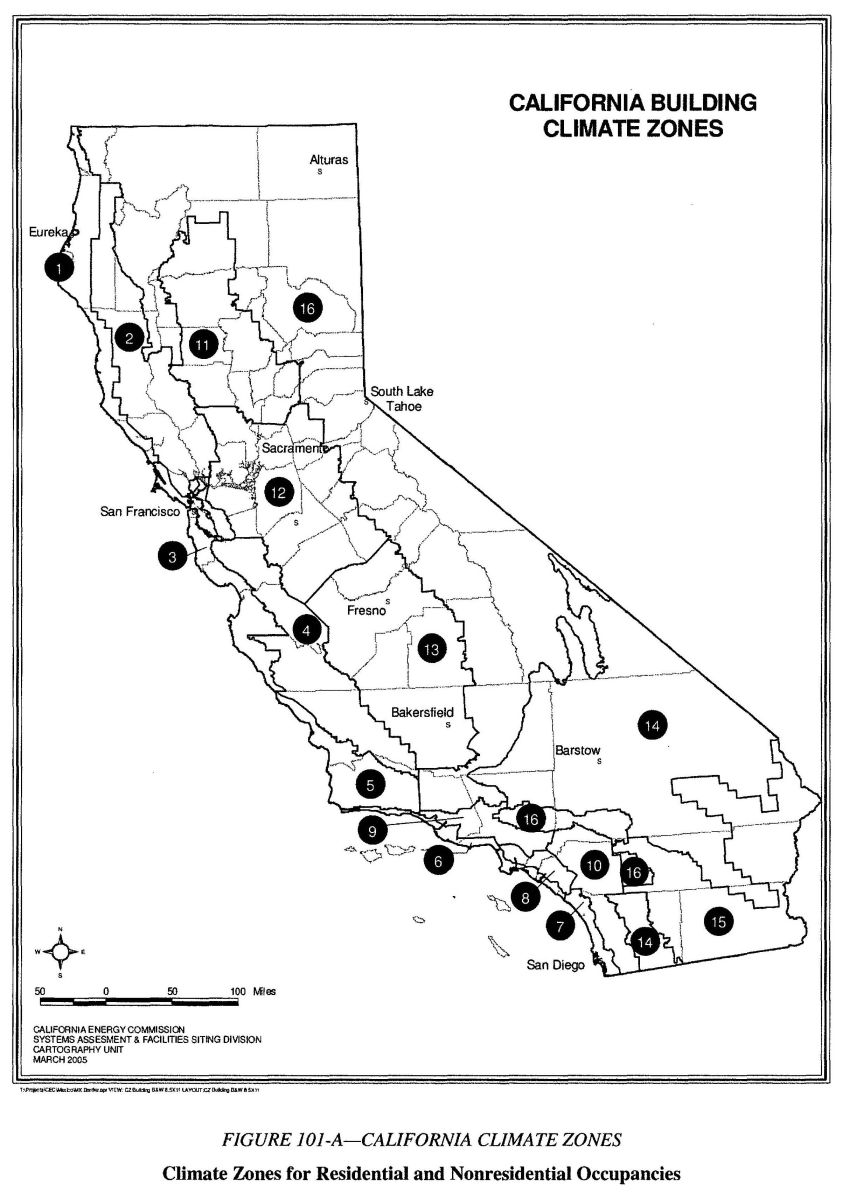
FIGURE 101-A—CALIFORNIA CLIMATE ZONES
Climate Zones for Residential and Nonresidential Occupancies
FIGURE 101-A CALIFORNIA CLIMATE ZONES
20Sections 111 through 119 establish requirements for manufacturing, construction and installation of certain systems, equipment and building components that are installed in buildings regulated by Title 24, Part 6. Systems, equipment and building components listed below may be installed only if:
No system, equipment or building component covered by the provisions of Sections 111 through 119 that is not certified or that fails to comply with the applicable installation requirements may be installed in a building regulated by Title 24, Part 6.
The systems, equipment and building components covered are:
Appliances regulated by the Appliance Efficiency Regulations (Section 111).
Other space-conditioning equipment (Section 112).
Other service water-heating systems and equipment (Section 113).
Pool and spa systems and equipment (Section 114).
Gas appliances (Section 115).
Doors, windows and fenestration products (Section 116).
Joints and other openings (Section 117).
Insulation and roofing products (Section 118).
Lighting control devices, ballasts and luminaires (Section 119).
Any appliance for which there is a California standard established in the Appliance Efficiency Regulations may be installed only if the manufacturer has certified to the Commission, as specified in those regulations, that the appliance complies with the applicable standard for that appliance. For certified appliances, go to www.energy.ca.gov/appliances/database.
Certification by manufacturers. Any space–conditioning equipment listed in this section may be installed only if the manufacturer has certified that the equipment complies with all the applicable requirements of this section.
Exception to Section 112(a): Water–cooled centrifugal water-chilling packages that are not designed for operation at ARI Standard 550 test conditions of 44°F leaving chilled water temperature and 85°F entering condenser water temperature shall have a minimum full load COP rating as shown in Tables 112-H, 112-I, and 112-J and a minimum NPLV rating as shown in Tables 112-K, 112-L and 112-M. The table values are only applicable over the following full load design ranges:
Leaving Chiller Water Temperature 40 to 48°F Entering Condenser Water Temperature 75 to 85°F Condensing Water Temperature Rise 5 to 15°F
21Exception to Section 112(b): The controls may allow supplementary heater operation during:
Exception to Section 112(c): Gravity gas wall heaters, gravity floor heaters, gravity room heaters, noncentral electric heaters, fireplaces or decorative gas appliances, wood stoves, room air conditioners, and room air-conditioner heat pumps need not comply with this requirement. Additionally, room air-conditioner heat pumps need not comply with Section 112(b). Under performance method of compliance, the resulting increase in energy use due to elimination of the setback thermostat shall be factored into the compliance analysis in accordance with a method prescribed by the Executive Director.
| EQUIPMENT TYPE | SIZE CATEGORY | EFFICIENCY1 | TEST PROCEDURE | |
|---|---|---|---|---|
| Before 1/1/2010 | After 1/1/2010 | |||
| 1. IPLVs are applicable only to equipment with capacity modulation. | ||||
| 2. Deduct 0.2 from the required EERs and IPLVs for units with a heating section other than electric resistance heat. | ||||
| Air conditioners, air cooled | ≥ 65,000 Btu/hr and <135,000 Btu/hr | 10.3 EER2 | 11.2 EER2 | ARI 340⁄360 |
| ≥135,000 Btu/hr and <240,000 Btu/hr | 9.7 EER2 | 11.0 EER2 | ARI 340⁄360 | |
| ≥240,000 Btu/hr and <760,000 Btu/hr | 9.5 EER2 and 9.7 IPLV2 | 10.0 EER2 and 9.7 IPLV2 | ||
| ≥760,000 Btu/hr | 9.2 EER2 and 9.4 IPLV2 | 9.7 EER2 and 9.4 IPLV2 | ||
| Air conditioners, water and evaporatively cooled | ARI 210⁄240 | |||
| >240,000 Btu/hr | 11.0 EER2 and 10.3 IPLV2 | ARI 340⁄360 | ||
| Condensing units, air cooled | ≥135,000 Btu/hr | 10.1 EER and 11.2 IPLV | ARI 365 | |
| Condensing units, water or evaporatively cooled | ≥135,000 Btu/hr | 13.1 EER and 13.1 IPLV | ||
| EQUIPMENT TYPE | SIZE CATEGORY | SUBCATEGORY OR RATING CONDITION | EFFICIENCY1 | TEST PROCEDURE | |
|---|---|---|---|---|---|
| Before 1/1/2010 | After 1/1/2010 | ||||
| 1. IPLVs and Part load rating conditions are applicable only to equipment with capacity modulation. | |||||
| 2. Deduct 0.2 from the required EERs and IPLVs for units with a heating section other than electric resistance heat. | |||||
| Air cooled (cooling mode) | ≥65,000 Btu/hr and >135,000 Btu/hr | Split system and single package | 10.1 EER2 | 11.0 | ARI 340⁄360 |
| ≥135,000 Btu/hr and <240,000 Btu/hr | Split system and single package | 9.3 EER2 | 10.6 | ARI 340⁄360 | |
| ≥240,000 Btu/hr | Split system and single package | 9.0 EER2 9.2 IPVL2 | 9.5EER2 and 9.2 IPLV2 | ||
| Air cooled (heating mode) | ≥65,000 Btu/hr and < 135,000 Btu/hr (cooling capacity) | 47°Fdb⁄43°Fwb outdoor air | 3.2 COP | 3.3 COP | ARI 210⁄240 |
| ≥135,000 Btu/hr (cooling capacity) | 47°Fdb⁄43°Fwb outdoor air | 3.1 COP | 3.2 COP | ARI 340⁄360 | |
| EQUIPMENT TYPE | SIZE CATEGORY | SUBCATEGORY OR RATING CONDITION | EFFICIENCY | TEST PROCEDURE |
|---|---|---|---|---|
| Air-cooled gas-engine heat pump (cooling mode) | All capacities | 95°F db outdoor air | 0.6 COP | ANSI Z21.40.4 |
| Air-cooled gas-engine heat pump (heating mode) | All capacities | 47°F db/43°F wb outdoor air | 0.72 COP | ANSI Z21.40.4 |
| EQUIPMENT TYPE | SIZE CATEGORY | EFFICIENCY | TEST PROCEDURE |
|---|---|---|---|
| Air cooled, with condenser, electrically operated | <150 tons | 2.80 COP 3.05 IPLV | ARI 550⁄590 |
| ≥150 tons | |||
| Air cooled, without condenser, electrically operated | All capacities | 3.10 COP 3.45 IPLV | |
| Water cooled, electrically operated, positive displacement (reciprocating) | All capacities | 4.20 COP 5.05 IPLV | ARI 550⁄590 |
| Water cooled, electrically operated, positive displacement (rotary screw and scroll) | <150 tons | 4.45 COP 5.20 IPLV | ARI 550/590 |
| ≥150 tons and <300 tons | 4.90 COP 5.60 IPLV | ||
| ≥300 tons | 5.50 COP 6.15 IPLV | ||
| Water cooled, electrically operated, centrifugal | <150 tons | 5.00 COP 5.25 IPLV | ARI 55/590 |
| ≥150 tons and <300 tons | 5.55 COP 5.90 IPLV | ||
| ≥300 tons | 6.10 COP 6.40 IPLV | ||
| Air cooled absorption single effect | All capacities | 0.60 COP | ARI 560 |
| Water cooled absorption single effect | All capacities | 0.70 COP | |
| Absorption double effect, indirect-fired | All capacities | 1.00 COP 1.05 IPLV | |
| Absorption double effect, direct-fired | All capacities | 1.00 COP 1.00 IPLV | |
| Water cooled gas engine driven chiller | All capacities | 1.2 COP 2.0 IPLV | ANSI Z21.40.4 |
| EQUIPMENT TYPE | SIZE CATEGORY(Input) | SUBCATEGORY OR RATING CONDITION | EFFICIENCY1 | TEST PROCEDURE |
|---|---|---|---|---|
| 1. Cap means the rated cooling capacity of the product in Btu/hr. If the unit's capacity is less than 7000 Btu/hr, use 7000 Btu/hr in the calculation. If the unit's capacity is greater than 15,000 Btu/hr, use 15,000 Btu/hr in the calculation. | ||||
| 2. Replacement units must be factory labeled as follows: “MANUFACTURED FOR REPLACEMENT APPLICATIONS ONLY; NOT TO BE INSTALLED IN NEW CONSTRUCTION PROJECTS.” Replacement efficiencies apply only to units with existing sleeves less than 16 inches high and less than 42 inches wide. | ||||
| PTAC (cooling mode) new construction | All capacities | 95°F db outdoor air | 12.5–(0.213×Cap⁄1000)1 EER | ARI 310⁄380 |
| PTAC (cooling mode) replacements2 | All capacities | 95°F db outdoor air | 10.9–(0.213×Cap⁄1000)1 EER | |
| PTHP (cooling mode) new construction | All capacities | 95°F db outdoor air | 12.3–(0.213×Cap⁄1000)1 EER | |
| PTHP (cooling mode) replacements2 | All capacities | 95°F db outdoor air | 10.8–(0.213×Cap⁄1000)1 EER | |
| PTHP (heating mode) new construction | All capacities | 3.2–(0.026×Cap⁄1000)1 COP | ||
| PTHP (heating mode) replacements2 | All capacities | 2.9–(0.026×Cap⁄1000)1 COP | ||
| SPVAC (cooling mode) | <65,000 Btu/h | 95°F db⁄75°F wb outdoor air | 9.0 EER | ARI 390 |
| ≥65,000 Btu/h and <135,000 Btu/h | 8.9 EER | |||
| ≥135,000 Btu/h and <240,000 Btu/h | 8.6 EER | |||
| SPVHP (cooling mode) | <65,000 Btu/h | 9.0 EER | ||
| ≥65,000 Btu/h and <135,000 Btu/h | 8.9 EER | |||
| ≥135,000 Btu/h and <240,000 Btu/h | 8.6 EER | |||
| SPVHP (heating mode) | <65,000 Btu/H and | 47°F db⁄43°F wb outdoor air | 3.0 COP | |
| ≥65,000 Btu/h and <135,000 Btu/h | 3.0 COP | |||
| ≥135,000 Btu/h and <240,000 Btu/h | 2.9 COP | |||
| EQUIPMENT TYPE | TOTAL SYSTEM HEAT REJECTION CAPACITY AT RATED CONDITIONS | SUBCATEGORY OR RATING CONDITION | PERFORMANCE REQUIRED1,2 | TEST PROCEDURE3 |
|---|---|---|---|---|
| 1. For purposes of this table, open cooling tower performance is defined as the maximum flow rating of the tower divided by the fan nameplate rated motor power. | ||||
| 2. For purposes of this table air-cooled condenser performance is defined as the heat rejected from the refrigerant divided by the fan nameplate rated motor power. | ||||
| 3. Open cooling towers shall be tested using the test procedures in CTI ATC-105. Performance of factory assembled open cooling towers shall be either certified as base models as specified in CTI STD-201 or verified by testing in the field by a CTI approved testing agency. Open factory assembled cooling towers with custom options added to a CTI certified base model for the purpose of safe maintenance or to reduce environmental or noise impact shall be rated at 90% of the CTI certified performance of the associated base model or at the manufacturer's stated performance, whichever is less. Base models of open factory assembled cooling towers are open cooling towers configured in exact accordance with the Data of Record submitted to CTI as specified by CTI STD-201. There are no certification requirements for field erected cooling towers. | ||||
| 4. The efficiencies for open cooling towers listed in Table 112-G are not applicable for closed-circuit towers. | ||||
| Propeller or axial fan open cooling towers | All | 95°F entering water 85°F leaving water 75°F wb outdoor air | >38.2 gpm⁄hp | CTI ATC-105 and CTI STD-201 |
| Centrifugal fan open cooling towers | All | 95°F entering water 85°F leaving water 75°F wb outdoor air | >20.0 gpm⁄hp | CTI ATC-105 and CTI STD-201 |
| Air-cooled condensers | All | 125°F condensing temperature R22 test fluid 190°F entering gas temperature 15°F subcooling 95°F entering drybulb | >176,000 Btu⁄hr hp | ARI 460 |
| CENTRIFUGAL CHILLERS < 150 Tons COPstd = 5.0 | ||||||||
|---|---|---|---|---|---|---|---|---|
| Leaving Chilled Water Temperature (°F) | Entering Condenser Water Temperature (°F) | LIFT1 (°F) | Condenser Flow Rate | |||||
| 2 gpm⁄ton | 2.5 gpm⁄ton | 3 gpm⁄ton | 4 gpm⁄ton | 5 gpm⁄ton | 6 gpm⁄ton | |||
| Required COP | ||||||||
| 1. LIFT = Entering Condenser Water Temperature (°F) − Leaving Chilled Water Temperature (°F) | ||||||||
| 2. Condenser DT = Leaving Condenser Water Temperature (°F) − Entering Condenser Water Temperature (°F) | ||||||||
| Kadj = 6.1507 − 0.30244(X) + 0.0062692(X)2 − 0.000045595(X)3 where X = Condenser DT + LIFT COPadj = Kadj * COPstd | ||||||||
| 46 | 75 | 29 | 5.58 | 5.83 | 6.03 | 6.32 | 6.54 | 6.70 |
| 45 | 75 | 30 | 5.50 | 5.74 | 5.92 | 6.19 | 6.38 | 6.53 |
| 44 | 75 | 31 | 5.42 | 5.65 | 5.82 | 6.07 | 6.24 | 6.37 |
| 43 | 75 | 32 | 5.35 | 5.57 | 5.72 | 5.95 | 6.11 | 6.23 |
| 42 | 75 | 33 | 5.27 | 5.49 | 5.64 | 5.85 | 6.00 | 6.11 |
| 41 | 75 | 34 | 5.19 | 5.41 | 5.56 | 5.75 | 5.89 | 5.99 |
| 46 | 80 | 34 | 5.19 | 5.41 | 5.56 | 5.75 | 5.89 | 5.99 |
| 40 | 75 | 35 | 5.11 | 5.33 | 5.48 | 5.67 | 5.79 | 5.88 |
| 45 | 80 | 35 | 5.11 | 5.33 | 5.48 | 5.67 | 5.79 | 5.88 |
| 44 | 80 | 36 | 5.03 | 5.26 | 5.40 | 5.58 | 5.70 | 5.79 |
| 43 | 80 | 37 | 4.94 | 5.18 | 5.32 | 5.50 | 5.62 | 5.70 |
| 42 | 80 | 38 | 4.84 | 5.10 | 5.25 | 5.43 | 5.53 | 5.61 |
| 41 | 80 | 39 | 4.73 | 5.01 | 5.17 | 5.35 | 5.46 | 5.53 |
| 46 | 85 | 39 | 4.73 | 5.01 | 5.17 | 5.35 | 5.46 | 5.53 |
| 40 | 80 | 40 | 4.62 | 4.92 | 5.09 | 5.27 | 5.38 | 5.45 |
| 45 | 85 | 40 | 4.62 | 4.92 | 5.09 | 5.27 | 5.38 | 5.45 |
| 44 | 85 | 41 | 4.49 | 4.82 | 5.00 | 5.20 | 5.30 | 5.38 |
| 43 | 85 | 42 | 4.35 | 4.71 | 4.91 | 5.12 | 5.23 | 5.22 |
| 42 | 85 | 43 | 4.19 | 4.59 | 4.81 | 5.03 | 5.15 | 5.14 |
| 41 | 85 | 44 | 4.02 | 4.46 | 4.70 | 4.94 | 5.06 | 5.06 |
| 40 | 85 | 45 | 3.84 | 4.32 | 4.58 | 4.84 | 4.98 | 4.68 |
| Condenser DT2 | 14.04 | 11.23 | 9.36 | 7.02 | 5.62 | 4.68 | ||
| CENTRIFUGAL CHILLERS > 150 TONS, ≤ 300 TONS COPstd = 5.55 | ||||||||
|---|---|---|---|---|---|---|---|---|
| Leaving Chilled Water Temperature (°F) | Entering Condenser Water Temperature (°F) | LIFT1 (°F) | Condenser Flow Rate | |||||
| 2 gpm/ton | 2.5 gpm/ton | 3 gpm/ton | 4 gpm/ton | 5 gpm/ton | 6 gpm/ton | |||
| Required COP | ||||||||
| 1. LIFT = Entering Condenser Water Temperature (°F)—Leaving Chilled Water Temperature (°F) | ||||||||
| 2. Condenser DT = Leaving Condenser Water Temperature (°F)—Entering Condenser Water Temperature (°F) | ||||||||
| Kadj=6.1507–0.30244(X)+0.0062692(X)2 – 0.000045595(X)3 where X = Condenser DT + LIFT COPadj=Kadj * COPstd | ||||||||
| 46 | 75 | 29 | 6.17 | 6.44 | 6.66 | 6.99 | 7.23 | 7.40 |
| 45 | 75 | 30 | 6.08 | 6.34 | 6.54 | 6.84 | 7.06 | 7.22 |
| 44 | 75 | 31 | 6.00 | 6.24 | 6.43 | 6.71 | 6.9 | 7.05 |
| 43 | 75 | 32 | 5.91 | 6.15 | 6.33 | 6.58 | 6.76 | 6.89 |
| 42 | 75 | 33 | 5.83 | 6.07 | 6.23 | 6.47 | 6.63 | 6.75 |
| 41 | 75 | 34 | 5.74 | 5.98 | 6.14 | 6.36 | 6.51 | 6.62 |
| 46 | 80 | 34 | 5.74 | 5.98 | 6.14 | 6.36 | 6.51 | 6.62 |
| 40 | 75 | 35 | 5.65 | 5.90 | 6.05 | 6.26 | 6.40 | 6.51 |
| 45 | 80 | 35 | 5.65 | 5.90 | 6.05 | 6.26 | 6.40 | 6.51 |
| 44 | 80 | 36 | 5.56 | 5.81 | 5.97 | 6.17 | 6.30 | 6.40 |
| 43 | 80 | 37 | 5.46 | 5.73 | 5.89 | 6.08 | 6.21 | 6.30 |
| 42 | 80 | 38 | 5.35 | 5.64 | 5.80 | 6.00 | 6.12 | 6.20 |
| 41 | 80 | 39 | 5.23 | 5.54 | 5.71 | 5.91 | 6.03 | 6.11 |
| 46 | 85 | 39 | 5.23 | 5.54 | 5.71 | 5.91 | 6.03 | 6.11 |
| 40 | 80 | 40 | 5.10 | 5.44 | 5.62 | 5.83 | 5.95 | 6.03 |
| 45 | 85 | 40 | 5.10 | 5.44 | 5.62 | 5.83 | 5.95 | 6.03 |
| 44 | 85 | 41 | 4.96 | 5.33 | 5.55 | 5.74 | 5.86 | 5.94 |
| 43 | 85 | 42 | 4.81 | 5.21 | 5.42 | 5.66 | 5.78 | 5.86 |
| 42 | 85 | 43 | 4.63 | 5.08 | 5.31 | 5.56 | 5.69 | 5.77 |
| 41 | 85 | 44 | 4.45 | 4.93 | 5.19 | 5.46 | 5.60 | 5.69 |
| 40 | 85 | 45 | 4.24 | 4.77 | 5.06 | 5.35 | 5.50 | 5.59 |
| Condenser DT2 | 14.04 | 11.23 | 9.36 | 7.02 | 5.62 | 4.68 | ||
| CENTRIFUGAL CHILLERS > 300 Tons COPstd=6.1 | ||||||||
|---|---|---|---|---|---|---|---|---|
| Leaving Chilled Water Temperature (°F) | Entering Condenser Water Temperature (°F) | LIFT1 (°F) | Condenser Flow Rate | |||||
| 2 gpm/ton | 2.5 gpm/ton | 3 gpm/ton | 4 gpm/ton | 5 gpm/ton | 6 gpm/ton | |||
| Required COP | ||||||||
| 1. LIFT = Entering Condenser Water Temperature (°F)–Leaving Chilled Water Temperature (°F) | ||||||||
| 2. Condenser DT = Leaving Condenser Water Temperature (°F)–Entering Condenser Water Temperature (°F) | ||||||||
| Kadj = 6.1507–0.30244(X)+0.0062692(X)2-0.000045595(X)3 where X = Condenser DT+LIFT COPadj = Kadj * COPstd | ||||||||
| 46 | 75 | 29 | 6.80 | 7.11 | 7.35 | 7.71 | 7.97 | 8.16 |
| 45 | 75 | 30 | 6.71 | 6.99 | 7.21 | 7.55 | 7.78 | 7.96 |
| 44 | 75 | 31 | 6.61 | 6.89 | 7.09 | 7.40 | 7.61 | 7.77 |
| 43 | 75 | 32 | 6.52 | 6.79 | 6.98 | 7.26 | 7.45 | 7.60 |
| 42 | 75 | 33 | 6.43 | 6.69 | 6.87 | 7.13 | 7.31 | 7.44 |
| 41 | 75 | 34 | 6.33 | 6.60 | 6.77 | 7.02 | 7.18 | 7.30 |
| 46 | 80 | 34 | 6.33 | 6.60 | 6.77 | 7.02 | 7.18 | 7.30 |
| 40 | 75 | 35 | 6.23 | 6.50 | 6.68 | 6.91 | 7.06 | 7.17 |
| 45 | 80 | 35 | 6.23 | 6.50 | 6.68 | 6.91 | 7.06 | 7.17 |
| 44 | 80 | 36 | 6.13 | 6.41 | 6.58 | 6.81 | 6.95 | 7.05 |
| 43 | 80 | 37 | 6.02 | 6.31 | 6.49 | 6.71 | 6.85 | 6.94 |
| 42 | 80 | 38 | 5.90 | 6.21 | 6.40 | 6.61 | 6.75 | 6.84 |
| 41 | 80 | 39 | 5.77 | 6.11 | 6.30 | 6.52 | 6.65 | 6.74 |
| 46 | 85 | 39 | 5.77 | 6.11 | 6.30 | 6.52 | 6.65 | 6.74 |
| 40 | 80 | 40 | 5.63 | 6.00 | 6.20 | 6.43 | 6.56 | 6.65 |
| 45 | 85 | 40 | 5.63 | 6.00 | 6.20 | 6.43 | 6.56 | 6.65 |
| 44 | 85 | 41 | 5.47 | 5.87 | 6.10 | 6.33 | 6.47 | 6.55 |
| 43 | 85 | 42 | 5.30 | 5.74 | 5.98 | 6.24 | 6.37 | 6.46 |
| 42 | 85 | 43 | 5.11 | 5.60 | 5.86 | 6.13 | 6.28 | 6.37 |
| 41 | 85 | 44 | 4.90 | 5.44 | 5.72 | 6.02 | 6.17 | 6.27 |
| 40 | 85 | 45 | 4.68 | 5.26 | 5.58 | 5.90 | 6.07 | 6.17 |
| Condenser DT2 | 14.04 | 11.23 | 9.36 | 7.02 | 5.62 | 4.68 | ||
| CENTRIFUGAL CHILLERS < 150 Tons IPIVstd = 5.25 | ||||||||
|---|---|---|---|---|---|---|---|---|
| Leaving Chilled Water Temperature (°F) | Entering Condenser Water Temperature (°F) | LIFT1 (°F) | Condenser Flow Rate | |||||
| 2 gpm/ton | 2.5 gpm/ton | 3 gpm/ton | 4 gpm/ton | 5 gpm/ton | 6 gpm/ton | |||
| Required IPLV/NPLV | ||||||||
| 1. LIFT = Entering Condenser Water Temperature (°F) – Leaving Chilled Water Temperature (°F) | ||||||||
| 2. Condenser DT=Leaving Condenser Water Temperature (°F) – Entering Condenser Water Temperature (°F) | ||||||||
| 3. AU values shown are NPLV except at conditions of 3 gpn/ton and 41 °F LIFT which is IPLV. | ||||||||
| Kadj = 6.1507 - 0.30244(X) + 0.0062692(X)2 - 0.000045595(X)3 where X=Condenser DT+LIFT COPadj=Kadj * COPstd | ||||||||
| 46 | 75 | 29 | 5.84 | 6.10 | 6.30 | 6.61 | 6.84 | 7.00 |
| 45 | 75 | 30 | 5.75 | 6.00 | 6.19 | 6.47 | 6.68 | 6.83 |
| 44 | 75 | 31 | 5.67 | 5.91 | 6.08 | 6.34 | 6.53 | 6.67 |
| 43 | 75 | 32 | 5.59 | 5.82 | 5.99 | 6.23 | 6.39 | 6.52 |
| 42 | 75 | 33 | 5.51 | 5.74 | 5.90 | 6.12 | 6.27 | 6.39 |
| 41 | 75 | 34 | 5.43 | 5.66 | 5.81 | 6.02 | 6.16 | 6.26 |
| 46 | 80 | 34 | 5.43 | 5.66 | 5.81 | 6.02 | 6.16 | 6.26 |
| 40 | 75 | 35 | 5.35 | 5.58 | 5.73 | 5.93 | 6.06 | 6.15 |
| 45 | 80 | 35 | 5.35 | 5.58 | 5.73 | 5.93 | 6.06 | 6.15 |
| 44 | 80 | 36 | 5.26 | 5.50 | 5.65 | 5.84 | 5.96 | 6.05 |
| 43 | 80 | 37 | 5.16 | 5.42 | 5.57 | 5.76 | 5.87 | 5.96 |
| 42 | 80 | 38 | 5.06 | 5.33 | 5.49 | 5.67 | 5.79 | 5.87 |
| 41 | 80 | 39 | 4.95 | 5.24 | 5.41 | 5.60 | 5.71 | 5.78 |
| 46 | 85 | 39 | 4.95 | 5.24 | 5.41 | 5.60 | 5.71 | 5.78 |
| 40 | 80 | 40 | 4.83 | 5.14 | 5.32 | 5.52 | 5.63 | 5.70 |
| 45 | 85 | 40 | 4.83 | 5.14 | 5.32 | 5.52 | 5.63 | 5.70 |
| 44 | 85 | 41 | 4.69 | 5.04 | 5.253 | 5.43 | 5.55 | 5.62 |
| 43 | 85 | 42 | 4.55 | 4.93 | 5.13 | 5.35 | 5.47 | 5.54 |
| 42 | 85 | 43 | 4.38 | 4.80 | 5.03 | 5.26 | 5.38 | 5.46 |
| 41 | 85 | 44 | 4.21 | 4.67 | 4.91 | 5.17 | 5.30 | 5.38 |
| 40 | 85 | 45 | 4.01 | 4.52 | 4.79 | 5.06 | 5.20 | 5.29 |
| Condenser DT2 | 14.04 | 11.23 | 9.36 | 7.02 | 5.62 | 4.68 | ||
| CENTRIFUGAL CHILLERS > 300 Tons IPLVstd = 6.4 | ||||||||
|---|---|---|---|---|---|---|---|---|
| Leaving Chilled Water Temperature (°F) | Entering Condenser Water Temperature (°F) | LIFT1 (°F) | Condenser Flow Rate | |||||
| 2 gpm/ton | 2.5 gpm/ton | 3 gpm/ton | 4 gpm/ton | 5 gpm/ton | 6 gpm/ton | |||
| Required IPLV/NPLV | ||||||||
| 1. LIFT = Entering Condenser Water Temperature (°F) – Leaving Chilled Water Temperature (°F) | ||||||||
| 2. Condenser DT=Leaving Condenser Water Temperature (°F)–Entering Condenser Water Temperature (°F) | ||||||||
| 3. All values shown are NPLV except at conditions of 3 gpn/ton and 41 °F LIFT which is IPLV. | ||||||||
| Kadj = 6.1507 – 0.30244(X) + 0.0062692(X)2–0.000045595(X)3 where X = Condenser DT + LIFT COPadj = Kadj * COPstd | ||||||||
| 46 | 75 | 29 | 7.15 | 7.47 | 7.72 | 8.10 | 8.37 | 8.58 |
| 45 | 75 | 30 | 7.05 | 7.35 | 7.58 | 7.93 | 8.18 | 8.36 |
| 44 | 75 | 31 | 6.95 | 7.23 | 7.45 | 7.77 | 8.00 | 8.16 |
| 43 | 75 | 32 | 6.85 | 7.13 | 7.33 | 7.63 | 7.83 | 7.98 |
| 42 | 75 | 33 | 6.75 | 7.03 | 7.22 | 7.49 | 7.68 | 7.82 |
| 41 | 75 | 34 | 6.65 | 6.93 | 7.12 | 7.37 | 7.55 | 7.67 |
| 46 | 80 | 34 | 6.65 | 6.93 | 7.12 | 7.37 | 7.55 | 7.67 |
| 40 | 75 | 35 | 6.55 | 6.83 | 7.01 | 7.26 | 7.42 | 7.54 |
| 45 | 80 | 35 | 6.55 | 6.83 | 7.01 | 7.26 | 7.42 | 7.54 |
| 44 | 80 | 36 | 6.44 | 6.73 | 6.92 | 7.15 | 7.30 | 7.41 |
| 43 | 80 | 37 | 6.32 | 6.63 | 6.82 | 7.05 | 7.19 | 7.30 |
| 42 | 80 | 38 | 6.20 | 6.53 | 6.72 | 6.95 | 7.09 | 7.19 |
| 41 | 80 | 39 | 6.06 | 6.42 | 6.62 | 6.85 | 6.99 | 7.08 |
| 46 | 85 | 39 | 6.06 | 6.42 | 6.62 | 6.85 | 6.99 | 7.08 |
| 40 | 80 | 40 | 5.91 | 6.30 | 6.52 | 6.76 | 6.89 | 6.98 |
| 45 | 85 | 40 | 5.91 | 6.30 | 6.52 | 6.76 | 6.89 | 6.98 |
| 44 | 85 | 41 | 5.75 | 6.17 | 6.403 | 6.66 | 6.79 | 6.89 |
| 43 | 85 | 42 | 5.57 | 6.03 | 6.28 | 6.55 | 6.70 | 6.79 |
| 42 | 85 | 43 | 5.37 | 5.88 | 6.16 | 6.44 | 6.59 | 6.69 |
| 41 | 85 | 44 | 5.15 | 5.71 | 6.01 | 6.33 | 6.49 | 6.59 |
| 40 | 85 | 45 | 4.91 | 5.53 | 5.86 | 6.20 | 6.37 | 6.48 |
| Condenser DT2 | 14.04 | 11.23 | 9.36 | 7.02 | 5.62 | 4.68 | ||
| CENTRIFUGAL CHILLERS > 300 Tons IPLVstd = 6.4 | ||||||||
|---|---|---|---|---|---|---|---|---|
| Leaving Chilled Water Temperature (°F) | Entering Condenser Water Temperature (°F) | LIFT1 (°F) | Condenser Flow Rate | |||||
| 2 gpm/ton | 2.5 gpm/ton | 3 gpm/ton | 4 gpm/ton | 5 gpm/ton | 6 gpm/ton | |||
| Required IPLV/NPLV | ||||||||
| 1. LIFT = Entering Condenser Water Temperature (°F)–Leaving Chilled Water Temperature (°F) | ||||||||
| 2. Condenser DT = Leaving Condenser Water Temperature (°F)– Entering Condenser Water Temperature (°F) | ||||||||
| 3. All values shown are NPLV except at conditions of 3 gpn/ton and 41 °F LIFT which is IPLV. | ||||||||
| Kadj=6.1507–0.30244(X)+0.0062692(X)2–0.000045595(X)3 COPadj=Kadj * COPstd | ||||||||
| 46 | 75 | 29 | 7.15 | 7.47 | 7.72 | 8.10 | 8.37 | 8.58 |
| 45 | 75 | 30 | 7.05 | 7.35 | 7.58 | 7.93 | 8.18 | 8.36 |
| 44 | 75 | 31 | 6.95 | 7.23 | 7.45 | 7.77 | 8.00 | 8.16 |
| 43 | 75 | 32 | 6.85 | 7.13 | 7.33 | 7.63 | 7.83 | 7.98 |
| 42 | 75 | 33 | 6.75 | 7.03 | 7.22 | 7.49 | 7.68 | 7.82 |
| 41 | 75 | 34 | 6.65 | 6.93 | 7.12 | 7.37 | 7.55 | 7.67 |
| 46 | 80 | 34 | 6.65 | 6.93 | 7.12 | 7.37 | 7.55 | 7.67 |
| 40 | 75 | 35 | 6.55 | 6.83 | 7.01 | 7.26 | 7.42 | 7.54 |
| 45 | 80 | 35 | 6.55 | 6.83 | 7.01 | 7.26 | 7.42 | 7.54 |
| 44 | 80 | 36 | 6.44 | 6.73 | 6.92 | 7.15 | 7.30 | 7.41 |
| 43 | 80 | 37 | 6.32 | 6.63 | 6.82 | 7.05 | 7.19 | 7.30 |
| 42 | 80 | 38 | 6.20 | 6.53 | 6.72 | 6.95 | 7.09 | 7.19 |
| 41 | 80 | 39 | 6.06 | 6.42 | 6.62 | 6.85 | 6.99 | 7.08 |
| 46 | 85 | 39 | 6.06 | 6.42 | 6.62 | 6.85 | 6.99 | 7.08 |
| 40 | 80 | 40 | 5.91 | 6.30 | 6.52 | 6.76 | 6.89 | 6.98 |
| 45 | 85 | 40 | 5.91 | 6.30 | 6.52 | 6.76 | 6.89 | 6.98 |
| 44 | 85 | 41 | 5.75 | 6.17 | 6.403 | 6.66 | 6.79 | 6.89 |
| 43 | 85 | 42 | 5.57 | 6.03 | 6.28 | 6.55 | 6.70 | 6.79 |
| 42 | 85 | 43 | 5.37 | 5.88 | 6.16 | 6.44 | 6.59 | 6.69 |
| 41 | 85 | 44 | 5.15 | 5.71 | 6.01 | 6.33 | 6.49 | 6.59 |
| 40 | 85 | 45 | 4.91 | 5.53 | 5.86 | 6.20 | 6.37 | 6.48 |
| Condenser DT2 | 14.04 | 11.23 | 9.36 | 7.02 | 5.62 | 4.68 | ||
Exception to Section 113(a)1: Residential occupancies.
Exception to Section 113(c)2: Water heating systems serving a single dwelling unit.
Exception to Section 113(c)6: Buildings for which the state architect determines that service water heating from site solar energy or recovered energy is economically or physically infeasible.
Exception 1 to Section 114(a)4: Listed package units with fully insulated enclosures, and with tight-fitting covers that are insulated to at least R-6.
Exception 2 to Section 114(a)4: Pools or spas deriving at least 60 percent of the annual heating energy from site solar energy or recovered energy.
Any natural gas system or equipment listed below may be installed only if it does not have a continuously burning pilot light:
Exception to Section 115(b): Household cooking appliances without an electrical supply voltage connection and in which each pilot consumes less than 150 Btu/hr.
Exception to Section 116(a)2: If the fenestration product is a skylight or is site-built fenestration in a building covered by the nonresidential standards with less than 10,000 square feet of site-built fenestration, the default U-factor may be calculated as set forth in Reference Nonresidential Appendix NA6.
Exception to Section 116(a)3: If the fenestration product is a skylight or is site-built fenestration in a building covered by the nonresidential standards with less than 10,000 square feet of site-built fenestration, the default SHGC may be calculated as set forth in Reference Nonresidential Appendix NA6.
Exception to Section 116(a): Fenestration products removed and reinstalled as part of a building alteration or addition.
Exception to Section 116(b): Unframed glass doors and fire doors need not be weatherstripped or caulked.
| FRAME1,2 | PRODUCT TYPE | SINGLE PANE U-FACTOR | DOUBLE PANE U-FACTOR | GLASS BLACK1 U-FACTOR |
|---|---|---|---|---|
| 1.For all dual-glazed fenestration products, adjust the listed U-factors as follows: a. Add 0.05 for products with dividers between panes if spacer is less than 7⁄16 inch wide. b. Add 0.05 to any product with true divided lite (dividers through the panes). | ||||
| 2. Translucent or transparent panels shall use glass block values. | ||||
| Metal | Operable | 1.28 | 0.79 | 0.87 |
| Fixed | 1.19 | 0.71 | 0.72 | |
| Greenhouse/garden window | 2.26 | 1.40 | NA | |
| Doors | 1.25 | 0.77 | NA | |
| Skylight | 1.98 | 1.3 | NA | |
| Metal, Thermal Break | Operable | NA | 0.66 | NA |
| Fixed | NA | 0.55 | NA | |
| Greenhouse/garden window | NA | 1.12 | NA | |
| Doors | NA | 0.59 | NA | |
| Skylight | NA | 1.11 | NA | |
| Nonmetal | Operable | 0.99 | 0.58 | 0.60 |
| Fixed | 1.04 | 0.55 | 0.57 | |
| Doors | 0.99 | 0.53 | NA | |
| Greenhouse/garden window | 1.94 | 1.06 | NA | |
| Skylight | 1.47 | 0.84 | NA | |
| FRAME TYPE | PRODUCT | GLAZING | TOTAL WINDOW SRGC1 | ||
|---|---|---|---|---|---|
| Single Pane | Double Pane | Glass Block1 | |||
| Translucent or transparent panels shall use glass block values. | |||||
| Metal | Operable | Clear | 0.80 | 0.70 | 0.70 |
| Fixed | Clear | 0.83 | 0.73 | 0.73 | |
| Operable | Tinted | 0.67 | 0.59 | NA | |
| Fixed | Tinted | 0.68 | 0.60 | NA | |
| Metal, Thermal Break | Operable | Clear | NA | 0.63 | NA |
| Fixed | Clear | NA | 0.69 | NA | |
| Operable | Tinted | NA | 0.53 | NA | |
| Fixed | Tinted | NA | 0.57 | NA | |
| Nonmetal | Operable | Clear | 0.74 | 0.65 | 0.70 |
| Fixed | Clear | 0.76 | 0.67 | 0.67 | |
| Operable | Tinted | 0.60 | 0.53 | NA | |
| Fixed | Tinted | 0.63 | 0.55 | NA | |
Joints and other openings in the building envelope that are potential sources of air leakage shall be caulked, gasketed, weather-stripped or otherwise sealed to limit infiltration and exfiltration.
Exception to Section 118(d)1: Where the accessible space in the attic is not large enough to accommodate the required R-value, the entire accessible space shall be filled with insulation, provided such installation does not violate Section 1203.2 of Title 24, Part 2.
Exception to Section 118(e)3: When there are conditioned spaces with a combined floor area no greater than 2,000 square feet in an otherwise unconditioned building, and when the average height of the space between the ceiling and the roof over these spaces is greater than 12 feet, insulation placed in direct contact with a suspended ceiling with removable ceiling panels shall be an acceptable method of reducing heat loss from a conditioned space and shall be accounted for in heat loss calculations.
Note: Vents that do not penetrate the roof deck, that are designed for wind resistance for roof membranes, are not within the scope of Section 118(e)2.
Exception to Section 118(i)1: Roofing products that are not certified according to Section 10-113 shall assume the following default aged reflectance⁄emittance values:
Exception 1 to Section 118(i)4B: Aluminum-pigmented asphalt roof coatings shall meet the requirements of ASTM D 2824 or ASTM D 6848 and be installed as specified by ASTM D 3805.
Exception 2 to Section 118(i)4B: Cement-based roof coatings shall contain a minimum of 20 percent cement and shall meet the requirements of ASTM C 1583, ASTM D 822 and ASTM D 5870.
Any lighting control device, ballast or luminaire subject to the requirements of Section 119 shall be installed only if the manufacturer has certified to the Commission that the device complies with all of the applicable requirements of Section 119.
Lighting control devices may be individual devices or systems consisting of two or more components. For control systems consisting of two or more components, such as an Energy Management Control System (EMCS), the manufacturer of the control system shall certify each of the components required for the system to comply with Section 119.
| INSULATION LOCATION | INSULATION ORIENTATION | INSTALLATION REQUIREMENTS | CLIMATE ZONE | INSULATION R-FACTOR |
|---|---|---|---|---|
| Outside edge of heated slab, either inside or outside the foundation wall | Vertical | From the level of the top of the slab, down 16 inches or to the frost line, whichever is greater. Insulation may stop at the top of the footing where this is less than the required depth. For below grade slabs, vertical insulation shall be extended from the top of the foundation wall to the bottom of the foundation (or the top of the footing) or to the frost line, whichever is greater. | 1-15 | 5 |
| 16 | 10 | |||
| Between heated slab and outside foundation wall | Vertical and Horizontal | Vertical insulation from top of slab at inside edge of outside wall down to the top of the horizontal insulation. Horizontal insulation from the outside edge of the vertical insulation extending 4 feet toward the center of the slab in a direction normal to the outside of the building in plan view. | 1-15 | 5 |
| 16 | 10 vertical and 7 horizontal |
| PHYSICAL PROPERTY | ASTM TEST PROCEDURE | REQUIREMENT |
|---|---|---|
| 1. Any cracking or checking visible to the eye fails the test procedure. | ||
| Initial percent elongation (break) | D 2370 | Minimum 200% 73°F (23°C) |
| Initial percent elongation (break) or Initial flexibility | D 2370 D 522, Test B | Minimum 60%0°F (–18°C) Minimum pass 1” mandrel 0°F(–18°C) |
| Initial tensile strength (maximum stress) | D 2370 | Minimum 100 psi (1.38 Mpa) 73°F (23°C) |
| Initial tensile strength (maximum stress) or Initial flexibility | D 2370 D 522, Test B | Minimum 200 psi (2.76 Mpa) 0°F (–18°C) Minimum pass 1” mandrel 0°F (—18°C) |
| Final percent elongation (break) after accelerated weathering 1000 h | D 2370 | Minimum 100% 73°F (23°C) |
| Final percent elongation (break) after accelerated weathering 100 h or Flexibility after accelerated weathering 100h | D2370 D 522, Test B | Minimum 40% 0°F (—18°C) Minimum pass 1” mandrel 0°F(—18°C) |
| performance | D1653 | Maximum 50 perms |
| Accelerated weathering 1000 h | D4798 | No cracking or checking1 |
| MIDFREQUENCY OF SOUND PRESSURE THIRD-OCTAVE BAND THIRD-OCTAVE BAND (in kHz) | MAXIMUM dB LEVEL WITHIN THIRD-OCTAVE BAND (in dB reference 20 micropascals) |
|---|---|
| Less than 20 | 80 |
| 20 or more to less than 25 | 105 |
| 25 or more to less than 31.5 | 110 |
| 31.5 or more | 115 |
Sections 121 through 129 establish requirements for the design and installation of space-conditioning and service water-heating systems and equipment in nonresidential, high-rise residential and hotel/motel buildings subject to Title 24, Part 6. All such buildings shall comply with the applicable provisions of Sections 121 through 129.
All nonresidential, high-rise residential and hotel/motel occupancies shall comply with the requirements of Sections 121(a) through 121(e).
Exception to Section 121(b)1A: Naturally ventilated spaces in high-rise residential dwelling units and hotel/motel guest rooms shall be open to and within 25 feet of operable wall or roof openings to the outdoors.
Exception to Section 121(b)2: Transfer air. The rate of outdoor air required by Section 121(b)2 may be provided with air transferred from other ventilated spaces if:
Exception 1 to Section 121(c)3: Classrooms, call centers, office spaces served by multiple zone systems that are continuously occupied during normal business hours with occupant density greater than 25 people per 1000 ft2 per Section 121(b)2B, healthcare facilities and medical buildings, and public areas of social services buildings are not required to have demand control ventilation.
Exception 2 to Section 121(c)3: Where space exhaust is greater than the design ventilation rate specified in Section 121(b)2B minus 0.2 cfm per ft2 of conditioned area.
Exception 3 to Section 121(c)3: Spaces that have processes or operations that generate dusts, fumes, mists, vapors or gases and are not provided with local exhaust ventilation, such as indoor operation of internal combustion engines or areas designated for unvented food service preparation, or beauty salons shall not install demand control ventilation.
Exception 4 to Section 121(c)3: Spaces with an area of less than 150 square feet, or a design occupancy of less than 10 people per Section 121(b)2B.
| TYPE OF USE | CFM PER SQUARE FOOT OF CONDITIONED FLOOR AREA |
|---|---|
| Auto repair workshops | 1.50 |
| Barber shops | 0.40 |
| Bars, cocktail lounges and casinos | 0.2 |
| Beauty shops | 0.40 |
| Coin-operated dry cleaning | 0.30 |
| Commercial dry cleaning | 0.45 |
| High-rise residential | Ventilation rates specified by the CBC |
| Hotel guest rooms (less than 500 ft2) | 30 cfm/guest room |
| Hotel guest rooms (500 ft2 or greater) | 0.15 |
| Retail stores | 0.20 |
| All others | 0.15 |
Space-conditioning systems shall be installed with controls that comply with the applicable requirements of Subsections (a) through (h).
Exception to Section 122(a): An independent perimeter heating or cooling system may serve more than one zone without individual thermostatic controls if:
Exception to Section 122(b)3: Systems with thermostats that require manual changeover between heating and cooling modes.
Exception to Section 122(b): Systems serving zones that must have constant temperatures to prevent degradation of materials, a process, plants or animals.
Exception to Section 122(e)1: Mechanical systems serving retail stores and associated malls, restaurants, grocery stores, churches and theaters equipped with 7-day programmable timers.
41Exception to Section 122(e)2A: Thermostat setback controls are not required in nonresidential buildings in areas where the Winter Median of Extremes outdoor air temperature determined in accordance with Section 144(b)4 is greater than 32°F.
The piping for all space-conditioning and service water-heating systems with fluid temperatures listed in Table 123-A shall have the amount of insulation specified in Subsection (a) or (b). Insulation conductivity shall be determined in accordance with ASTM C 335 at the mean temperature listed in Table 123-A, and shall be rounded to the nearest 1/100 Btu-inch per hour per square foot per °F.
Insulation shall be protected from damage, including that due to sunlight, moisture, equipment maintenance and wind, including but not limited to, the following:
Insulation exposed to weather shall be suitable for outdoor service, e.g., protected by aluminum, sheet metal, painted canvas or plastic cover. Cellular foam insulation shall be protected as above or painted with a coating that is water retardant and provides shielding from solar radiation that can cause degradation of the material.
Insulation covering chilled water piping and refrigerant suction piping located outside the conditioned space shall include a vapor retardant located outside the insulation (unless the insulation is inherently vapor retardant), all penetrations and joints of which shall be sealed.
Exception 1 to Section 123: Factory-installed piping within space-conditioning equipment certified under Section 111 or 112.
Exception 2 to Section 123: Piping that conveys fluids with a design operating temperature range between 60°F and 105°F.
Exception 3 to Section 123: Piping that serves process loads, gas piping, cold domestic water piping, condensate drains, roof drains, vents or waste piping.
Exception 4 to Section 123: Where the heat gain or heat loss to or from piping without insulation will not increase building source energy use.
42Exception 5 to Section 123: Piping that penetrates framing members shall not be required to have pipe insulation for the distance of the framing penetration. Metal piping that penetrates metal framing shall use grommets, plugs, wrapping or
other insulating material to assure that no contact is made with the metal framing.
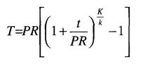
| FLUID TEMPERATURE RANGE, (°F) | CONDUCTIVITY RANGE (in Btu-inch per hour per square foot per °F) | INSULATION MEAN RATING TEMPERATURE (°F) | NOMINAL PIPE DIAMETER (in inches) | |||||
|---|---|---|---|---|---|---|---|---|
| Runouts up to 2 | 1 and less | 1.25–2 | 2.50–4 | 5–6 | 8 and larger | |||
| INSULATION THICKNESS REQUIRED (in inches) | ||||||||
| Space heating systems (steam, steam condensate and hot water) | ||||||||
| Above 350 | 0.32-0.34 | 250 | 1.5 | 2.5 | 2.5 | 3.0 | 3.5 | 3.5 |
| 251-350 | 0.29-0.31 | 200 | 1.5 | 2.0 | 2.5 | 2.5 | 3.5 | 3.5 |
| 201-250 | 0.27-0.30 | 150 | 1.0 | 1.5 | 1.5 | 2.0 | 2.0 | 3.5 |
| 141-200 | 0.25-0.29 | 125 | 0.5 | 1.5 | 1.5 | 1.5 | 1.5 | 1.5 |
| 105-140 | 0.24-0.28 | 100 | 0.5 | 1.0 | 1.0 | 1.0 | 1.5 | 1.5 |
| Service water-heating systems (recirculating sections, all piping in electric trace tape systems, and the first 8 feet of piping from the storage tank for nonrecirculating systems) | ||||||||
| Above 105 | 0.24-0.28 | 100 | 0.5 | 1.0 | 1.0 | 1.5 | 1.5 | 1.5 |
| Space cooling systems (chilled water, refrigerant and brine) | ||||||||
| 40-60 | 0.23-0.27 | 75 | 0.5 | 0.5 | 0.5 | 1.0 | 1.0 | 1.0 |
| Below 40 | 0.23-0.27 | 75 | 1.0 | 1.0 | 1.5 | 1.5 | 1.5 | 1.5 |
Exception to Section 125(a)4: Air economizers installed by the HVAC system manufacturer and certified to the Commission as being factory calibrated and tested are not required to be field tested per NA7.5.4.2.
A refrigerated warehouse with total cold storage and frozen storage area of 3,000 ft2 or larger shall meet the requirements of this section.
Exception 1 to Section 126: A refrigerated space less than 3,000 ft2 shall meet the Appliance Efficiency Regulations for walk-in refrigerators or freezers.
Exception 2 to Section 126: Areas within refrigerated warehouses that are designed solely for the purpose of quick chilling or freezing of products with design cooling capacities of greater than 240 Btu⁄hr-ft2 (2 tons per 100 ft2).
| SPACE | SURFACE | MINIMUM R-VALUE (°F-hr-sf/Btu) |
|---|---|---|
| Frozen storage | Roof/Ceiling | R-36 |
| Wall | R-36 | |
| Floor | R-36 | |
| Cold storage | Roof/Ceiling | R-28 |
| Wall | R-28 |
Exception to Section 126(b): Underslab heating systems controlled such that the electric resistance heat is thermostatically controlled and disabled during the summer on-peak period defined by the local electric utility.
Exception to Section 126(c)2: Evaporators served by a single compressor without unloading capability.
Exception to Section 126(d)3. Unitary condensing units.
Exception to Section 126(e)2: Refrigeration plants with more than one dedicated compressor per suction group.
Reserved.
Reserved.
Reserved.
Exception 1 to Section 131(a): 1. Up to 3 watts per square foot of lighting in any area within a building that must be continuously illuminated for reasons of building security or emergency egress, if:
Exception 2 to Section 131(a): Public areas with switches that are accessible only to authorized personnel.
Exceptions to Section 131(b):
- Lights in corridors.
- A space that has only one luminaire with no more than two lamps.
Exception to Section 131(c)2A: Primary sidelit and skylit daylight areas that have a combined area totaling less than or equal to 250 square feet within any enclosed space.
Exception 1 to Section 131(c)2B: Where the total skylit daylight area in any enclosed space is less than or equal to 2,500 square feet.
Exception 2 to Section 131(c)2B: Skylit daylight areas where existing adjacent structures obstruct direct beam sunlight for at least 6 hours per day during the equinox as calculated using computer or graphical methods.
Exception 3 to Section 131(c)2B: When the skylight effective aperture is greater than 4.0 percent, and all general lighting in the skylit area is controlled by a multilevel astronomical time switch that meets the requirements of Section 119(h) and that has an override switch that meets the requirements of Section 131(d)2.
Exception 4 to Section 131(c)2B: Skylit daylight areas where the effective aperture is less than 0.006. The effective aperture for skylit daylight areas is specified in Section 146(a)2E.
Exception 1 to Section 131(c)2C: Where the total primary sidelit daylight area in any enclosed space has an area less than or equal to 2,500 square feet.
Exception 2 to Section 131(c)2C: Primary sidelit daylight areas where the effective aperture is less than 0.1. The effective aperture for primary sidelit daylight areas is specified in Section 146(a)2E.
Exception 4 to Section 131(c)2C: Parking garages.
Exception 1 to Section 131(c)2D(iii): Controlled lighting having a lighting power density less than 0.3 W/ft2.
Exception 2 to Section 131(c)2D(iii): When skylights are replaced or added to on an existing building with an existing general lighting system.
Exception 1 to Section 131(d)1: Where the lighting system is serving an area that must be continuously lit, 24 hours per day/365 days per year.
Exception 2 to Section 131(d)1: Lighting in corridors, guest rooms and dwelling units of high-rise residential buildings and hotel/motels, and parking garages.
Exception 3 to Section 131(d)1: Up to 0.3 watts per square foot of lighting in any area within a building that must be continuously illuminated for reasons of building security or emergency egress, provided that the area is designated a security or emergency egress area is designated a security or emergency egress area on the plans and specifications submitted to the enforcement agency under Section 10-103(a)2 of Title 24, Part 1.
Exception to Section 131(d)2D: In malls, auditoriums, single tenant retail spaces, industrial facilities and arenas where captive-key override is utilized, override time may exceed 2 hours.
Exception to Section 131(d)2E: In malls, auditoriums, single tenant retail spaces, industrial facilities, convention centers and arenas, the area controlled may not exceed 20,000 square feet.
Exception to Section 131(d)3: Retail stores and associated malls, restaurants, grocery stores, churches and theaters.
Exception to Section 131(g): Buildings where more than 50 percent of the lighting power is controlled by day lighting controls.
Exception 1 to Section 132(a): Lighting required by a health or life safety statute, ordinance or regulation, including but not limited to, emergency lighting.
Exception 2 to Section 132(a): Lighting used in or around swimming pools, water features or other locations subject to Article 680 of the California Electrical Code.
Exception 3 to Section 132(a): Searchlights.
Exception 4 to Section 132(a): Theme lighting for use in theme parks.
Exception 5 to Section 132(a): Lighting for film or live performances.
Exception 6 to Section 132(a): Temporary outdoor lighting.
Exception 7 to Section 132(a): Light emitting diode, light emitting capacitors, neon and cold cathode lighting.
Exception 8 to Section 132(a): Sign lighting.
Exception 1 to Section 132(b): Signs.
Exception 2 to Section 132(b): Lighting for building facades, public monuments, statues and vertical surfaces of bridges.
Exception 3 to Section 132(b): Lighting required by a health or life safety statute, ordinance or regulation, including but not limited to, emergency lighting.
Exception 4 to Section 132(b): Temporary outdoor lighting.
Exception 5 to Section 132(b): Lighting used in or around swimming pools, water features or other locations subject to Article 680 of the California Electrical Code.
Exception 6 to Section 132(b): Replacement of existing pole mounted luminaires in hardscape areas meeting all of the following conditions:
Exception to Section 132(c)1: Lighting in tunnels and large covered areas that require illumination during daylight hours.
Exception 1 to Section 132(c)2: Lighting required by a health or life-safety statute, ordinance or regulation, including but not limited to, emergency lighting.
Exception 2 to Section 132(c)2: Lighting for steps or stairs that require illumination during daylight hours.
Exception 3 to Section 132(c)2: Lighting that is controlled by a motion sensor and photocontrol.
Exception 4 to Section 132(c)2: Lighting for facilities that have equal lighting requirements at all hours and are designed to operate continuously.
Exception 5 to Section 132(c)2: Temporary outdoor lighting.
Exception 6 to Section 132(c)2: Signs.
Exception to Section 133(a)2: Outdoor signs in tunnels and large covered areas that require illumination during daylight hours.
Exception 1 to Section 133(a)3: Signs that are illuminated for less than one hour per day during daylight hours.
Exception 2 to Section 133(a)3: Outdoor signs in tunnels and large covered areas that require illumination during daylight hours.
Exception 3 to Section 133(a)3: Metal halide, high pressure sodium, cold cathode and neon lamps used to illuminated signs or parts of signs.
Exception to Section 133(a)4: EMCs required by a health or life safety statue, ordinance or regulation, including but not limited to exit signs and traffic signs.
—Reserved.
Reserved.
Reserved.
Reserved.
Reserved.
The envelope and the space-conditioning, lighting and service water-heating systems of all nonresidential, high-rise residential and hotel⁄motel buildings subject to Title 24, Part 6, shall be designed, constructed and installed in accordance with either:
In order to meet the energy budget, a proposed building’s use of TDV energy calculated under Subsection (b) must be no greater than the TDV energy budget calculated under Subsection (a).
In order to comply with the prescriptive approach under this section, a building shall be designed with and shall have constructed and installed:
A building complies with this section by being designed with and having constructed and installed either (1) envelope components that comply with each of the requirements in Subsection (a) for each individual component, and the requirements of Subsection (c) where they apply, or (2) an envelope that complies with the overall requirements in Subsection (b) and the requirements of Subsection (c) where they apply. When making calculations under Subsection (a) or (b), all of the rules listed in Section 141(c)1, 4 and 5 shall apply.
Exception 1 to Section 143(a)1Ai: Woodframed roofs in climate zones 3 and 5 are exempt from the minimum requirements for solar reflectance and thermal emittance or SRI if the roof assembly has a U-factor of 0.039 or lower.
Exception 2 to Section 143(a)1Ai: Metal building roofs in climate zones 3 and 5 are exempt from the minimum requirements for solar reflectance and thermal emittance or SRI if the roof assembly has a U-factor of 0.048 or lower.
Exception 3 to Section 143(a)1Ai: Roof area covered by building integrated photovoltaic panels and building integrated solar thermal panels are not required to meet the minimum requirements for solar reflectance and thermal emittance or SRI.
Exception 4 to Section 143(a)1Ai: Roof constructions that have thermal mass over the roof membrane with a weight of at least 25 1b/ft2.
Exception to Section 143(a)5A: Window area in demising walls is not counted as part of the window area for this requirement. Demising wall area is not counted as part of the gross exterior wall area or display perimeter.
Exception to Section 143(a)5C: The applicable “north” value for relative solar heat gain in
| CLIMATE ZONES | ||||||||||||||||||
|---|---|---|---|---|---|---|---|---|---|---|---|---|---|---|---|---|---|---|
| 1 | 2 | 3 | 4 | 5 | 6 | 7 | 8 | 9 | 10 | 11 | 12 | 13 | 14 | 15 | 16 | |||
| 1. Mass, light walls are defined as having a heat capacity greater than or equal to 7.0 Btu/h-ft2. Heavy mass walls are defined as having a heat capacity greater than or equal to 15.0 Btu/h-ft2. | ||||||||||||||||||
| 2. No skylight SHGC requirements are defined for climate zones 1 and 16. A climate zone without a requirement is designated as “NR”. | ||||||||||||||||||
| Roofs/ceilings | Metal building | 0.065 | 0.065 | 0.065 | 0.065 | 0.065 | 0.065 | 0.065 | 0.065 | 0.065 | 0.065 | 0.065 | 0.065 | 0.065 | 0.065 | 0.065 | 0.065 | |
| Wood framed and other | 0.049 | 0.039 | 0.039 | 0.039 | 0.049 | 0.075 | 0.067 | 0.067 | 0.039 | 0.039 | 0.039 | 0.039 | 0.039 | 0.039 | 0.039 | 0.039 | ||
| Roofing products | Low-sloped | Aged reflectance emittance | NR | 0.55 | 0.55 | 0.55 | 0.55 | 0.55 | 0.55 | 0.55 | 0.55 | 0.55 | 0.55 | 0.55 | 0.55 | 0.55 | 0.55 | NR |
| NR | 0.75 | 0.75 | 0.75 | 0.75 | 0.75 | 0.75 | 0.75 | 0.75 | 0.75 | 0.75 | 0.75 | 0.75 | 0.75 | 0.75 | NR | |||
| Steep sloped (less than 5 1b/ft2) | NR | 0.20 | 0.20 | 0.20 | 0.20 | 0.20 | 0.20 | 0.20 | 0.20 | 0.20 | 0.20 | 0.20 | 0.20 | 0.20 | 0.20 | 0.20 | ||
| NR | 0.75 | 0.75 | 0.75 | 0.75 | 0.75 | 0.75 | 0.75 | 0.75 | 0.75 | 0.75 | 0.75 | 0.75 | 0.75 | 0.75 | 0.75 | |||
| Steep sloped (5 lb/ft2 or more) | 0.15 | 0.15 | 0.15 | 0.15 | 0.15 | 0.15 | 0.15 | 0.15 | 0.15 | 0.15 | 0.15 | 0.15 | 0.15 | 0.15 | 0.15 | 0.15 | ||
| 0.75 | 0.75 | 0.75 | 0.75 | 0.75 | 0.75 | 0.75 | 0.75 | 0.75 | 0.75 | 0.75 | 0.75 | 0.75 | 0.75 | 0.75 | 0.75 | |||
| Walls 1 | Metal building | 0.113 | 0.061 | 0.113 | 0.061 | 0.061 | 0.113 | 0.113 | 0.061 | 0.061 | 0.061 | 0.061 | 0.061 | 0.061 | 0.061 | 0.057 | 0.061 | |
| Metal-framed | 0.098 | 0.062 | 0.082 | 0.062 | 0.062 | 0.098 | 0.098 | 0.062 | 0.062 | 0.062 | 0.062 | 0.062 | 0.062 | 0.062 | 0.062 | 0.062 | ||
| Mass light | 0.196 | 0.170 | 0.268 | 0.227 | 0.44 | 0.44 | 0.44 | 0.44 | 0.44 | 0.170 | 0.170 | 0.170 | 0.170 | 0.170 | 0.170 | 0.170 | ||
| Mass heavy | 0.253 | 0.650 | 0.650 | 0.650 | 0.650 | 0.690 | 0.690 | 0.690 | 0.690 | 0.650 | 0.184 | 0.253 | 0.211 | 0.184 | 0.184 | 0.160 | ||
| Wood-framed and other | 0.102 | 0.059 | 0.110 | 0.059 | 0.102 | 0.110 | 0.110 | 0.102 | 0.059 | 0.059 | 0.059 | 0.059 | 0.059 | 0.059 | 0.042 | 0.059 | ||
| Floors/soffils | Mass | 0.092 | 0.092 | 0.269 | 0.269 | 0.269 | 0.269 | 0.269 | 0.269 | 0.269 | 0.269 | 0.092 | 0.092 | 0.092 | 0.092 | 0.092 | 0.058 | |
| Other | 0.048 | 0.039 | 0.071 | 0.071 | 0.071 | 0.071 | 0.071 | 0.071 | 0.071 | 0.071 | 0.039 | 0.071 | 0.071 | 0.039 | 0.039 | 0.039 | ||
| Windows | U-factor | 0.47 | 0.47 | 0.77 | 0.77 | 0.77 | 0.77 | 0.77 | 0.77 | 0.77 | 0.47 | 0.47 | 0.47 | 0.47 | 0.47 | 0.47 | 0.47 | |
| RSHG North | 0-10% WWR | 0.72 | 0.61 | 0.61 | 0.61 | 0.61 | 0.61 | 0.61 | 0.61 | 0.61 | 0.61 | 0.61 | 0.61 | 0.61 | 0.61 | 0.61 | 0.72 | |
| 10-20% WWR | 0.49 | 0.51 | 0.61 | 0.61 | 0.61 | 0.61 | 0.61 | 0.61 | 0.61 | 0.51 | 0.51 | 0.51 | 0.51 | 0.51 | 0.51 | 0.49 | ||
| 20-30% WWR | 0.47 | 0.47 | 0.61 | 0.61 | 0.61 | 0.61 | 0.61 | 0.61 | 0.61 | 0.47 | 0.47 | 0.47 | 0.47 | 0.47 | 0.47 | 0.47 | ||
| 30-40% WWR | 0.47 | 0.47 | 0.61 | 0.61 | 0.61 | 0.61 | 0.61 | 0.61 | 0.61 | 0.47 | 0.47 | 0.47 | 0.47 | 0.40 | 0.40 | 0.47 | ||
| RSHG Non-North | 0-10% WWR | 0.49 | 0.47 | 0.61 | 0.61 | 0.61 | 0.61 | 0.61 | 0.61 | 0.61 | 0.47 | 0.47 | 0.47 | 0.47 | 0.46 | 0.46 | 0.49 | |
| 10-20% WWR | 0.43 | 0.36 | 0.55 | 0.55 | 0.55 | 0.61 | 0.61 | 0.61 | 0.61 | 0.36 | 0.36 | 0.36 | 0.36 | 0.36 | 0.36 | 0.43 | ||
| 20-30% WWR | 0.43 | 0.36 | 0.41 | 0.41 | 0.41 | 0.39 | 0.39 | 0.39 | 0.39 | 0.36 | 0.36 | 0.36 | 0.36 | 0.36 | 0.36 | 0.43 | ||
| 30-40% WWR | 0.43 | 0.31 | 0.41 | 0.41 | 0.41 | 0.34 | 0.34 | 0.34 | 0.34 | 0.31 | 0.31 | 0.31 | 0.31 | 0.31 | 0.31 | 0.43 | ||
| Doors, U-factor | Nonswinging | 0.50 | 1.45 | 1.45 | 1.45 | 1.45 | 1.45 | 1.45 | 1.45 | 1.45 | 1.45 | 1.45 | 1.45 | 1.45 | 1.45 | 1.45 | 1.50 | |
| Swinging | 0.70 | 0.70 | 0.70 | 0.70 | 0.70 | 0.70 | 0.70 | 0.70 | 0.70 | 0.70 | 0.70 | 0.70 | 0.70 | 0.70 | 0.70 | 0.70 | ||
| Skylight2 | U-factor | Glass, curb | 1.11 | 1.11 | 1.11 | 1.11 | 1.11 | 1.11 | 1.11 | 1.11 | 1.11 | 1.11 | 1.11 | 1.11 | 1.11 | 1.11 | 1.11 | 1.11 |
| Glass, no curb | 0.68 | 0.68 | 0.82 | 0.82 | 0.82 | 0.82 | 0.82 | 0.82 | 0.82 | 0.68 | 0.68 | 0.68 | 0.68 | 0.68 | 0.68 | 0.68 | ||
| Plastic | 1.04 | 1.11 | 1.11 | 1.11 | 1.11 | 1.11 | 1.11 | 1.11 | 1.11 | 1.11 | 1.11 | 1.11 | 1.11 | 1.11 | 1.11 | 1.04 | ||
| SHGC | Glass, 0-2% | NR | 0.46 | 0.57 | 0.57 | 0.57 | 0.57 | 0.57 | 0.57 | 0.57 | 0.46 | 0.46 | 0.46 | 0.46 | 0.46 | 0.46 | NR | |
| Glass, 2.1-5% | NR | 0.36 | 0.40 | 0.40 | 0.40 | 0.40 | 0.40 | 0.40 | 0.40 | 0.36 | 0.36 | 0.36 | 0.36 | 0.36 | 0.36 | NR | ||
| Plastic, 0-2% | 0.69 | 0.69 | 0.69 | 0.69 | 0.69 | 0.69 | 0.69 | 0.69 | 0.69 | 0.69 | 0.69 | 0.69 | 0.69 | 0.69 | 0.69 | 0.69 | ||
| Plastic, 2.1-5% | 0.57 | 0.57 | 0.57 | 0.57 | 0.57 | 0.57 | 0.57 | 0.57 | 0.57 | 0.57 | 0.57 | 0.57 | 0.57 | 0.57 | 0.57 | 0.57 | ||
Table 143-A, 143-B or 143-C or 0.56, whichever is greater, shall be used for windows:
EQUATION 143-A RELATIVE SOLAR HEAT GAIN
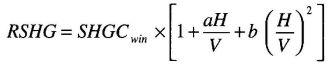
where:
RSHG = relative solar heat gain.
SHGCwin = solar heat gain coefficient of the window.
H = horizontal projection of the overhang from the surface of the window in feet, but no greater than V.
V = vertical distance from the window sill to the bottom of the overhang, in feet.
a = -0.41 for north-facing windows, -1.22 for south-facing windows and -0.92 for east- and west-facing windows.
b = 0.20 for north-facing windows, 0.66 for south-facing windows and 0.35 for east-and west-facing windows.
Exception to Section 143(a)6A: Atria over 55 feet high shall have a skylight area no greater than 10 percent of the gross exterior roof area.
| CLIMATE ZONES | ||||||||||||||||||
|---|---|---|---|---|---|---|---|---|---|---|---|---|---|---|---|---|---|---|
| 1 | 2 | 3 | 4 | 5 | 6 | 7 | 8 | 9 | 10 | 11 | 12 | 13 | 14 | 15 | 16 | |||
| 1. Mass, light walls are defined as having a heat capacity greater than or equal to 7.0 Btu/h-ft2. Heavy mass walls are defined as having a heat capacity greater than or equal to 15.0 Btu/h-ft2. | ||||||||||||||||||
| 2. No skylight SHGC requirements are defined for climate zones 1 and 16. A climate zone without a requirement is designated as “NR”. | ||||||||||||||||||
| Roofs/ceilings | Metal building | 0.065 | 0.065 | 0.065 | 0.065 | 0.065 | 0.065 | 0.065 | 0.065 | 0.065 | 0.065 | 0.065 | 0.065 | 0.065 | 0.065 | 0.065 | 0.065 | |
| Wood framed and other | 0.034 | 0.028 | 0.039 | 0.028 | 0.039 | 0.039 | 0.039 | 0.028 | 0.028 | 0.028 | 0.028 | 0.028 | 0.028 | 0.028 | 0.028 | 0.028 | ||
| Roofing Products | Low-sloped | Aged reflectance emittance | NR | NR | NR | NR | NR | NR | NR | NR | NR | 0.55 | 0.55 | NR | 0.55 | 0.55 | 0.55 | NR |
| NR | NR | NR | NR | NR | NR | NR | NR | NR | 0.75 | 0.75 | NR | 0.75 | 0.75 | 0.75 | NR | |||
| Walls1 | Metal building | 0.061 | 0.061 | 0.061 | 0.061 | 0.061 | 0.061 | 0.061 | 0.061 | 0.061 | 0.061 | 0.057 | 0.057 | 0.057 | 0.057 | 0.057 | 0.057 | |
| Metal-framed | 0.105 | 0.105 | 0.105 | 0.105 | 0.105 | 0.105 | 0.105 | 0.105 | 0.105 | 0.105 | 0.105 | 0.105 | 0.105 | 0.105 | 0.105 | 0.105 | ||
| Mass light | 0.170 | 0.170 | 0.170 | 0.170 | 0.170 | 0.227 | 0.227 | 0.227 | 0.196 | 0.170 | 0.170 | 0.170 | 0.170 | 0.170 | 0.170 | 0.170 | ||
| Mass heavy | 0.160 | 0.160 | 0.160 | 0.184 | 0.211 | 0.690 | 0.690 | 0.690 | 0.690 | 0.690 | 0.184 | 0.253 | 0.211 | 0.184 | 0.184 | 0.160 | ||
| Wood-framed and other | 0.059 | 0.059 | 0.059 | 0.059 | 0.059 | 0.059 | 0.059 | 0.059 | 0.059 | 0.059 | 0.042 | 0.059 | 0.059 | 0.042 | 0.042 | 0.042 | ||
| Floors/soffits | Mass | 0.045 | 0.045 | 0.058 | 0.058 | 0.058 | 0.069 | 0.092 | 0.092 | 0.092 | 0.069 | 0.058 | 0.058 | 0.058 | 0.045 | 0.058 | 0.037 | |
| Other | 0.034 | 0.034 | 0.039 | 0.039 | 0.039 | 0.039 | 0.071 | 0.039 | 0.039 | 0.039 | 0.039 | 0.039 | 0.039 | 0.034 | 0.039 | 0.034 | ||
| Windows | U-factor | 0.47 | 0.47 | 0.47 | 0.47 | 0.47 | 0.47 | 0.47 | 0.47 | 0.47 | 0.47 | 0.47 | 0.47 | 0.47 | 0.47 | 0.47 | 0.47 | |
| RSHG North | 0-10% WWR | 0.68 | 0.49 | 0.61 | 0.61 | 0.61 | 0.61 | 0.61 | 0.61 | 0.61 | 0.49 | 0.49 | 0.49 | 0.49 | 0.47 | 0.47 | 0.68 | |
| 10-20% WWR | 0.68 | 0.49 | 0.61 | 0.61 | 0.61 | 0.61 | 0.61 | 0.61 | 0.61 | 0.49 | 0.49 | 0.49 | 0.49 | 0.43 | 0.43 | 0.68 | ||
| 20-30% WWR | 0.47 | 0.40 | 0.61 | 0.61 | 0.61 | 0.61 | 0.61 | 0.61 | 0.61 | 0.40 | 0.40 | 0.40 | 0.40 | 0.43 | 0.43 | 0.47 | ||
| 30-40% WWR | 0.47 | 0.40 | 0.55 | 0.55 | 0.55 | 0.61 | 0.61 | 0.61 | 0.61 | 0.40 | 0.40 | 0.40 | 0.40 | 0.41 | 0.41 | 0.47 | ||
| RSHG Non-north | 0-10% WWR | 0.46 | 0.36 | 0.41 | 0.41 | 0.41 | 0.47 | 0.47 | 0.47 | 0.47 | 0.36 | 0.36 | 0.36 | 0.36 | 0.36 | 0.36 | 0.46 | |
| 10-20% WWR | 0.46 | 0.36 | 0.40 | 0.40 | 0.40 | 0.40 | 0.40 | 0.40 | 0.40 | 0.36 | 0.36 | 0.36 | 0.36 | 0.31 | 0.31 | 0.46 | ||
| 20-30% WWR | 0.36 | 0.31 | 0.31 | 0.31 | 0.31 | 0.36 | 0.36 | 0.36 | 0.36 | 0.31 | 0.31 | 0.31 | 0.31 | 0.26 | 0.26 | 0.36 | ||
| 30-40% WWR | 0.30 | 0.26 | 0.26 | 0.26 | 0.26 | 0.31 | 0.31 | 0.31 | 0.31 | 0.26 | 0.26 | 0.26 | 0.26 | 0.26 | 0.26 | 0.30 | ||
| Doors, U-factor | Nonswinging Swinging | 0.50 | 1.45 | 1.45 | 1.45 | 1.45 | 1.45 | 1.45 | 1.45 | 1.45 | 1.45 | 1.45 | 1.45 | 1.45 | 1.45 | 1.45 | 1.50 | |
| 0.70 | 0.70 | 0.70 | 0.70 | 0.70 | 0.70 | 0.70 | 0.70 | 0.70 | 0.70 | 0.70 | 0.70 | 0.70 | 0.70 | 0.70 | 0.70 | |||
| Skylight2 | U-factor | Glass, curb | 1.11 | 1.11 | 1.11 | 1.11 | 1.11 | 1.11 | 1.11 | 1.11 | 1.11 | 1.11 | 1.11 | 1.11 | 1.11 | 1.11 | 1.11 | 1.11 |
| Glass, no curb | 0.68 | 0.68 | 0.82 | 0.82 | 0.82 | 0.82 | 0.82 | 0.82 | 0.82 | 0.68 | 0.68 | 0.68 | 0.68 | 0.68 | 0.68 | 0.68 | ||
| Plastic | 1.11 | 1.11 | 1.11 | 1.11 | 1.11 | 1.11 | 1.11 | 1.11 | 1.11 | 1.11 | 1.11 | 1.11 | 1.11 | 1.11 | 1.11 | 1.11 | ||
| SHGC | Glass, 0-2% | 0.46 | 0.46 | 0.57 | 0.57 | 0.57 | 0.57 | 0.57 | 0.57 | 0.57 | 0.46 | 0.46 | 0.46 | 0.46 | 0.46 | 0.46 | 0.46 | |
| Glass, 2.1-5% | 0.36 | 0.32 | 0.32 | 0.32 | 0.32 | 0.40 | 0.40 | 0.40 | 0.40 | 0.32 | 0.32 | 0.32 | 0.32 | 0.31 | 0.31 | 0.36 | ||
| Plastic, 0-2% | 0.69 | 0.57 | 0.57 | 0.57 | 0.57 | 0.57 | 0.57 | 0.57 | 0.57 | 0.57 | 0.57 | 0.57 | 0.57 | 0.57 | 0.57 | 0.57 | ||
| Plastic, 2.5-5% | 0.55 | 0.34 | 0.39 | 0.39 | 0.39 | 0.57 | 0.57 | 0.57 | 0.57 | 0.34 | 0.34 | 0.34 | 0.34 | 0.27 | 0.27 | 0.55 | ||
| ALL CLIMATE ZONES | ||
|---|---|---|
| Note: Construction assembly U-factors shall be calculated in accordance with Reference Joint Appendix JA4. | ||
| Roof/Ceiling U-factor | ||
| Metal building | 0.048 | |
| Wood-framed and other | 0.039 | |
| Roofing products — aged reflectance/emittance | 0.55/0.75 | |
| Low-sloped | 0.20/0.75 | |
| Steep-sloped —Less than 5 1b/ft2 5 1b/ft2 or more | 0.15/0.75 | |
| Wall U-factor | ||
| Wood frame | 0.059 | |
| Metal frame | 0.062 | |
| Metal building | 0.057 | |
| Mass/7.0 ≤ HC | 0.170 | |
| Other | 0.059 | |
| Floor/Soffit U-factor Wood-framed and other | 0.048 | |
| Windows | ||
| U-factor | 0.47 | |
| Relative solar heat gain | ||
| 0 – 10% WWR | 0.36 | |
| 11 – 20% WWR | 0.31 | |
| 21 – 30% WWR | 0.26 | |
| 31 – 40% WWR | 0.26 | |
| Skylights | ||
| Doors, U-factor | Nonswinging | 0.50 |
| Swinging | 0.70 | |
| U-factor | Glass w/curb | 0.99 |
| Glass wo/curb | 0.57 | |
| Plastic w/curb | 0.87 | |
| SHGC Glass | 0 – 2% | 0.46 |
| 2.1 – 5% | 0.36 | |
| SHGC Plastic | 0 – 2% | 0.69 |
| 2.1 – 5% | 0.57 | |
The manufacturer/builder shall place two metal identification labels on each relocatable building module, one mechanically fastened and visible from the exterior and the other mechanically fastened to the interior frame above the ceiling, at the end of the module. In addition to information required by the Division of the State Architect (DSA), the labels shall state either “Complies with Title 24, Part 6 for all Climate Zones” or “Complies with Title 24, Part 6 for Climate Zones” and then list all of the climate zones for which the manufacturer has manufactured the relocatable building to comply. The location of the identification labels shall be shown on the building plans.
60Exception 1 to Section 143(c): Auditoriums, churches, movie theaters, museums and refrigerated warehouses.
Exception 2 to Section 143(c): In buildings with unfinished interiors, future enclosed spaces where it is planned to have less than or equal to 8,000 square feet of floor area, or ceiling heights less than or equal to 15 feet, based on proposed future interior wall and ceiling locations as delineated in the plans. This exception shall not apply to these future enclosed spaces when interior walls and ceilings are installed for the first time, the enclosed space floor area is greater than 8,000 square feet, and the ceiling height is greater than 15 feet (see Section 149(b)1M). This exception shall not be used for S-1 or S-2 (storage), or for F-1 or F-2 (factory) occupancies.
Exception 3 to Section 143(c): Enclosed spaces having a designed general lighting system with a lighting power density less than 0.5 watts per square foot.
A building complies with this section by being designed with and having constructed and installed a space-conditioning system that meets the requirements of Subsections (a) through (k).
Exception 1 to Section 144(a): Where it can be demon strated to the satisfaction of the enforcing agency that oversizing will not increase building TDV energy use.
Exception 2 to Section 144(a): Standby equipment with controls that allow the standby equipment to operate only when the primary equipment is not operating.
Exception 3 to Section 144(a): Multiple units of the same equipment type, such as multiple chillers and boilers, having combined capacities exceeding the design load, if they have controls that sequence or otherwise optimally control the operation of each unit based on load.
Exception to Section 144(b)4: Cooling design temperatures for cooling towers shall be no greater than the 0.5 percent Cooling Design Wet bulb values.
EQUATION 144-A ADJUSTED FAN POWER INDEX
Adjusted fan power index = Fan power index × Fan adjustment
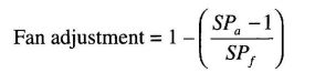
where:
SPa = Air pressure drop across the air-treatment or filtering system.
SPf = Total pressure drop across the fan.
Exception 1 to Section 144(d): Zones served by variable air-volume systems that are designed and controlled to reduce, to a minimum, the volume of reheated, recooled or mixed air supply are allowed only if the controls meet the following requirements:
Exception 2 to Section 144(d): Zones with special pressurization relationships or cross-contamination control needs.
Exception 3 to Section 144(d): Zones served by space-conditioning systems in which at least 75 percent of the energy for reheating, or providing warm air in mixing systems, is provided from a site-recovered or site-solar energy source.
Exception 4 to Section 144(d): Zones in which specific humidity levels are required to satisfy process needs.
Exception 5 to Section 144(d): Zones with a peak supply-air quantity of 300 cfm or less.
Exception 1 to Section 144(e)1: Where it can be shown to the satisfaction of the enforcing agency that special outside air filtration and treatment, for the reduction and treatment of unusual outdoor contaminants, makes compliance infeasible.
Exception 2 to Section 144(e)1: Where the use of outdoor air for cooling will affect other systems, such as humidification, dehumidification or supermarket refrigeration systems, so as to increase overall building TDV energy use.
Exception 3 to Section 144(e)1: Systems serving high-rise residential living quarters and hotel/motel guest rooms.
Exception 4 to Section 144(e)1: Where it can be shown to the satisfaction of the enforcing agency that the use of outdoor air is detrimental to equipment or materials in a space or room served by a dedicated space-conditioning system, such as a computer room or telecommunications equipment room.
Exception 5 to Section 144(e)1: Where electrically operated unitary air conditioners and heat pumps have cooling efficiencies that meet or exceed the efficiency requirements of Tables 144-A and 144-B.
Exception to Section 144(e)2A: Systems that provide 75 percent of the annual energy used for mechanical heating from site-recovered energy or a site-solar energy source.
Air distribution systems serving zones that are likely to have constant loads, such as interior zones, shall be designed for the air flows resulting from the fully reset supply air temperature.
Exception 1 to Section 144(f): Systems that meet the requirements of Section 144(d), without using Exception 1 or 2 to that section.
Exception 2 to Section 144(f): Where supply-air temperature reset would increase overall building energy use.
Exception 3 to Section 144(f): Zones in which specific humidity levels are required to satisfy process needs.
Exception 1 to Section 144(g): Where an electric resistance heating system supplements a heating system in which at least 60 percent of the annual energy requirement is supplied by site-solar or recovered energy.
Exception 2 to Section 144(g): Where an electric resistance heating system supplements a heat pump heating system, and the heating capacity of the heat pump is more than 75 percent of the design heating load calculated in accordance with Section 144(a) at the design outdoor temperature specified in Section 144(b)4.
Exception 3 to Section 144(g): Where the total capacity of all electric resistance heating systems serving the entire building is less than 10 percent of the total design output capacity of all heating equipment serving the entire building.
63Exception 4 to Section 144(g): Where the total capacity of all electric resistance heating systems serving the building, excluding those allowed under Exception 2, is no more than 3 kW.
Exception 5 to Section 144(g): Where an electric resistance heating system serves an entire building that is not a high-rise residential or hotel/motel building; and has a conditioned floor area no greater than 5,000 square feet; and has no mechanical cooling; and is in an area where natural gas is not currently available and an extension of a natural gas system is impractical, as determined by the natural gas utility.
Exception 1 to Section 144(h)2: Heat rejection devices included as an integral part of the equipment listed in Tables 112-A through 112-E.
Exception 2 to Section 144(h)2: Condenser fans serving multiple refrigerant circuits.
Exception 3 to Section 144(h)2: Condenser fans serving flooded condensers.
Exception 4 to Section 144(h)2: Up to one third of the fans on a condenser or tower with multiple fans where the lead fans comply with the speed control requirement.
Exception 1 to Section 144(h)4: Cooling towers that are ducted (inlet or discharge) or have an external sound trap that requires external static pressure capability.
| CLIMATE ZONE | SIZE CATEGORY | |||
|---|---|---|---|---|
| > = 760,000 | > = 240,000 and <760,000 | > = 135,000 and <240,000 | > = 65,000 and <135,000 | |
| 1 | N/A | N/A | N/A | N/A |
| 2 | N/A | N/A | N/A | N/A |
| 3 | N/A | N/A | N/A | N/A |
| 4 | 11.9 (before 1/1/2010) 12.5 (as of 1/1/2010) | 12.2 (before 1/1/2010) 12.9 (as of 1/1/2010) | 12.4 (before 1/1/2010) 14.1 (as of 1/1/2010) | N/A |
| 5 | N/A | N/A | N/A | N/A |
| 6 | N/A | N/A | N/A | N/A |
| 7 | N/A | N/A | N/A | N/A |
| 8 | 11.9 (before 1/1/2010) 12.5 (as of 1/1/2010) | 12.2 (before 1/1/2010) 12.9 (as of 1/1/2010) | 12.4 (before 1/1/2010) 14.1 (as of 1/1/2010) | N/A |
| 9 | 11.6 (before 1/1/2010) 12.2 (as of 1/1/2010) | 11.9 (before 1/1/2010) 12.5 (as of 1/1/2010) | 12.1 (before 1/1/2010) 13.7 (as of 1/1/2010) | N/A |
| 10 | 11.4 (before 1/1/2010) 12.0 (as of 1/1/2010) | 11.7 (before 1/1/2010) 12.3 (as of 1/1/2010) | 11.9 (before 1/1/2010) 13.5 (as of 1/1/2010 | 12.4 (before 1/1/2010) 13.5 (as of 1/1/2010) |
| 11 | 11.5 (before 1/1/2010) 12.1 (as of 1/1/2010) | 11.8 (before 1/1/2010) 12.4 (as of 1/1/2010) | 12.0 (before 1/1/2010) 13.6 (as of 1/1/2010) | N/A |
| 12 | 11.7(before 1/1/2010) 12.3 (as of 1/1/2010) | 12.0 (before 1/1/2010) 12.6 (as of 1/1/2010) | 12.2 (before 1/1/2010) 13.8 (as of 1/1/2010) | N/A |
| 13 | 11.2 (before 1/1/2010) 11.8 (as of 1/1/2010) | 11.5 (before 1/1/2010) 12.1 (as of 1/1/2010) | 11.7 (before 1/1/2010) 13.3 (as of 1/1/2010) | 12.3 (before 1/1/2010) 13.4 (as of 1/1/2010) |
| 14 | 11.7 (before 1/1/2010) 12.3 (as of 1/1/2010) | 12.0 (before 1/1/2010) 12.6 (as of 1/1/2010) | 12.2 (before 1/1/2010) 13.8 (as of 1/1/2010) | N/A |
| 15 | 10.0 (before 1/1/2010) 10.6 (as of 1/1/2010) | 10.4 (before 1/1/2010) 11.0 (as of 1/1/2010) | 10.6 (before 1/1/2010) 12.0 (as of 1/1/2010) | 11.3 (before 1/1/2010) 12.3 (as of 1/1/2010) |
| 16 | N/A | N/A | N/A | N/A |
Exception 1 to Section 144(i): Where the designer demonstrates that the water quality at the building site fails to meet manufacturer’s specifications for the use of water-cooled equipment.
Exception 2 to Section 144(i): Plants that employ a cooling thermal energy storage system.
Exception 3 to Section 144(i): Air cooled chillers with minimum efficiencies approved by the Commission pursuant to Section 10-109(d).
Exception 1 to Section 144(j)1: Systems that include no more than three control valves.
Exception 2 to Section 144(j)1: Systems having a total pump system power less than or equal to 1½hp.
| CLIMATE ZONE | SIZE CATEGORY | ||
|---|---|---|---|
| > = 240,000 | > = 135,000 and <240,000 | > = 65,000 and <135,000 | |
| 1 | N/A | N/A | N/A |
| 2 | N/A | N/A | N/A |
| 3 | N/A | N/A | N/A |
| 4 | 11.7 (before 1/1/2010) 13.8 (as of 1/1/2010) | 12.1 (before 1/1/2010) 13.8 (as of 1/1/2010) | N/A |
| 5 | N/A | N/A | N/A |
| 6 | N/A | N/A | N/A |
| 7 | 12.3 (before 1/1/2010) 14.5 (as of 1/1/2010) | N/A | N/A |
| 8 | 11.7 (before 1/1/2010) 13.8 (as of 1/1/2010) | 12.0 (before 1/1/2010) 13.7 (as of 1/1/2010) | N/A |
| 9 | 11.3 (before 1/1/2010) 13.3 (as of 1/1/2010) | 11.7 (before 1/1/2010) 13.3 (as of 1/1/2010) | 12.5 (before 1/1/2010) 13.6 (as of 1/1/2010) |
| 10 | 11.1 (before 1/1/2010) 13.1 (as of 1/1/2010) | 11.5 (before 1/1/2010) 13.1 (as of 1/1/2010) | 12.3 (before 1/1/2010) 13.4 (as of 1/1/2010) |
| 11 | 11.3 (before 1/1/2010) 13.3 (as of 1/1/2010) | 11.6 (before 1/1/2010) 13.2 (as of 1/1/2010) | 12.4 (before 1/1/2010) 13.5 (as of 1/1/2010) |
| 12 | 11.5 (before 1/1/2010) 13.5 (as of 1/1/2010) | 11.8 (before 1/1/2010) 13.4 (as of 1/1/2010) | N/A |
| 13 | 10.9 (before 1/1/2010) 12.8 (as of 1/1/2010) | 11.3 (before 1/1/2010) 12.9 (as of 1/1/2010) | 12.1 (before 1/1/2010) 13.2 (as of 1/1/2010) |
| 14 | 11.5 (before 1/1/2010) 13.5 (as of 1/1/2010) | 11.8 (before 1/1/2010) 13.4 (as of 1/1/2010) | N/A |
| 15 | 9.8 (before 1/1/2010) 11.5 (as of 1/1/2010) | 10.1 (before 1/1/2010) 11.5 (as of 1/1/2010) | 11.1 (before 1/1/2010) 12.1 (as of 1/1/2010) |
| 16 | N/A | N/A | N/A |
Exception to Section 144(j)4: Hydronic systems that use variable flow to reduce pumping energy in accordance with 144(j)1.
Exception 1 to Section 144(j)6: Heating hot water systems.
Exception 2 to Section 144(j)6: Condenser water systems serving only water-cooled chillers.
Exception to Section 144(j)7: Where a system loop temperature optimization controller is used to determine the most efficient operating temperature based on real-time conditions of demand and capacity, dead bands of less than 20°F shall be allowed.
Exception to Section 144(k)3B: Where the roof meets the requirements of Section 143(a)1C.
The leakage rate shall be confirmed through field verification and diagnostic testing, in accordance with procedures set forth in the Reference Nonresidential Appendix NA1.
| DEVICE TYPE | CLIMATE ZONES | REQUIRED HIGH LIMIT (ECONOMIZER OFF WHEN): | |
|---|---|---|---|
| Equation | Description | ||
| 1. Fixed enthalpy controls are prohibited in climate zones 1, 2, 3, 5, 11, 13, 14, 15 and 16. | |||
| 2. At altitudes substantially different than sea level, the fixed enthalpy limit value shall be set to the enthalpy value at 75°F and 50 percent relative humidity. As an example, at approximately 6000-foot elevation, the fixed enthalpy limit is approximately 30.7 Btu⁄Ib. | |||
| 3. Setpoint ”A” corresponds to a curve on the psychometric chart that goes through a point at approximately 75°F and 40 percent relative humidity and is nearly parallel to dry bulb lines at low humidity levels and nearly parallel to enthalpy lines at high humidity levels. | |||
| Fixed dry bulb | 1, 2, 3, 5, 11, 13, 14, 15 and 16 | TOA>75°F | Outdoor air temperature exceeds 75°F |
| 4, 6, 7, 8, 9, 10 and 12 | TOA>70°F | Outdoor air temperature exceeds 70°F | |
| Differential dry bulb | All | TOA>TRA | Outdoor air temperature exceeds return air temperature |
| Fixed enthalpy1 | 4, 6, 7, 8, 9, 10 and 12 | HOA>28 Btu⁄lb2 | Outdoor air enthalpy exceeds 28 Btu⁄lb of dry air2 |
| Electronic enthalpy | All | (TOA RHOA)>A | Outdoor air temperature⁄RH exceeds the “A” setpoint curve3 |
| Differential enthalpy | All | hOA> hRA | Outdoor air enthalpy exceeds return air enthalpy |
A building complies with this section if the actual lighting power density calculated under Subsection (a) is no greater than the allowed indoor lighting power density calculated under Subsection (c).
Exception to Section 146(a). Up to 0.2 watts per square foot of portable lighting for office areas shall not be required to be included in the calculation of actual indoor lighting power density.
EQUATION 146-A
EFFECTIVE APERTURE OF THE PRIMARY SIDELIT AREA
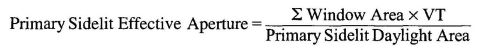
where,
Window area = rough opening of windows adjacent to the sidelit area, ft2
Window VT = visible light transmittance of window, no units
Primary sidelit daylight area = see Section 131(c)1 daylight area, primary sidelit
EQUATION 146-B
EFFECTIVE APERTURE OF THE SECONDARY SIDELIT AREA
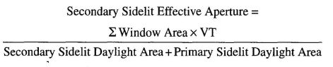
where,
Window area = rough opening of windows adjacent to the sidelit area, ft2
Window VT = visible light transmittance of window, no units
Primary sidelit daylight area = see Section 131(c)1B daylight area, primary sidelit
Secondary sidelit daylight area = see Section 131(c)1C daylight area, secondary sidelit.
EQUATION 146-C EFFECTIVE APERTURE OF SKYLIGHTS
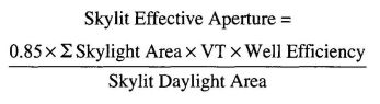
where,
Skylight area = the area of each individual skylight
Skylit daylight area = see Section 131(c)1D Daylight area, Skylit
VT = visible light transmittance
The VT shall include all skylighting system accessories including diffusers, louvers and other attachments that impact the diffusion of skylight into the space. The visible light transmittance of movable accessories shall be rated in the full open position. When the visible light transmittance of glazing and accessories are rated separately, the overall glazing transmittance is the product of the visible light transmittances of the glazings and accessories.
Well efficiency equals the ratio of the amount of visible light leaving a skylight well to the amount of visible light entering the skylight well. Well efficiency shall be determined from Equation 146-F or Table 146-B for specular and tubular light wells and from Table 146-A for all other light wells, based on the weighted average reflectance of the walls of the well and the geometry of the light well, or other test method approved by the Commission.
The well efficiency for nonspecular or nontubular light wells is based on the average weighted reflectance of the walls of the light well and the well cavity ratio. The well cavity ratio (WCR) is determined by the geometry of the skylight well and shall be determined using either Equation 146-D or Equation 146-E.
EQUATION 146-D
WELL CAVITY RATIO FOR RECTANGULAR WELLS
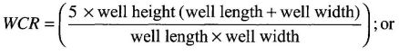
EQUATION 146-E
WELL CAVITY RATIO FOR NONRECTANGULAR-SHAPED WELLS
Where the well perimeter and well area are measured at the bottom of the well.
EQUATION 146-F
WELL EFFICIENCY FOR SPECULAR TUBULAR LIGHT WELLS
where,
ρ = specular reflectance of interior light well wall
L⁄D = ratio of light well length to light well interior diameter
| LIGHT WELL WALL REFLECTANCE | ||||||
|---|---|---|---|---|---|---|
| WCR | ρ= 99% | ρ = 90% | ρ = 80% | ρ = 70% | ρ = 60% | ρ = 40% |
| 0 | 1.00 | 1.00 | 1.00 | 1.00 | 1.00 | 1.00 |
| 1 | 1.00 | 0.98 | 0.96 | 0.94 | 0.92 | 0.89 |
| 2 | 0.99 | 0.95 | 0.91 | 0.88 | 0.84 | 0.78 |
| 4 | 0.99 | 0.90 | 0.82 | 0.76 | 0.70 | 0.61 |
| 6 | 0.98 | 0.85 | 0.74 | 0.65 | 0.58 | 0.48 |
| 8 | 0.97 | 0.79 | 0.66 | 0.56 | 0.49 | 0.38 |
| 10 | 0.96 | 0.74 | 0.59 | 0.49 | 0.41 | 0.31 |
| 12 | 0.95 | 0.70 | 0.53 | 0.43 | 0.35 | 0.26 |
| 14 | 0.95 | 0.66 | 0.48 | 0.38 | 0.31 | 0.22 |
| 16 | 0.94 | 0.62 | 0.44 | 0.34 | 0.27 | 0.18 |
| 18 | 0.93 | 0.59 | 0.41 | 0.31 | 0.24 | 0.16 |
| 20 | 0.92 | 0.56 | 0.38 | 0.28 | 0.21 | 0.14 |
| Light Well Reflectance (ñ) | |||||||
|---|---|---|---|---|---|---|---|
| L⁄D | ρ = 99% | ρ = 97% | ρ = 95% | ρ = 92% | ρ = 90% | ρ = 85% | ρ = 80% |
| 0.5 | 0.99 | 0.97 | 0.95 | 0.91 | 0.89 | 0.84 | 0.78 |
| 1.0 | 0.98 | 0.94 | 0.89 | 0.83 | 0.79 | 0.70 | 0.61 |
| 1.5 | 0.97 | 0.90 | 0.84 | 0.76 | 0.71 | 0.58 | 0.48 |
| 2.0 | 0.96 | 0.87 | 0.80 | 0.69 | 0.63 | 0.49 | 0.37 |
| 2.5 | 0.95 | 0.85 | 0.75 | 0.63 | 0.56 | 0.41 | 0.29 |
| 3.0 | 0.94 | 0.82 | 0.71 | 0.58 | 0.50 | 0.34 | 0.23 |
| 3.5 | 0.93 | 0.79 | 0.67 | 0.53 | 0.44 | 0.29 | 0.18 |
| 4.0 | 0.92 | 0.76 | 0.64 | 0.48 | 0.39 | 0.24 | 0.14 |
| 4.5 | 0.91 | 0.74 | 0.60 | 0.44 | 0.35 | 0.20 | 0.11 |
| 5.0 | 0.90 | 0.71 | 0.57 | 0.40 | 0.31 | 0.17 | 0.09 |
| 5.5 | 0.88 | 0.68 | 0.52 | 0.35 | 0.26 | 0.13 | 0.06 |
| 6.0 | 0.87 | 0.65 | 0.48 | 0.30 | 0.22 | 0.10 | 0.04 |
Exception to Section 146(b)2: Additional lighting power allowed according to Table 146-F footnotes shall not be traded.
Exception to Section 146(b)4: Allowed lighting power may be traded from primary function areas using the Area Category Method to primary function areas using the Tailored Method.
70Exception to Section 146(c)1: When using the Complete Building Method, if a parking garage and another type of use are part of a single building, the parking garage portion of the building and the remaining portion of the building shall each sepa-
rately use the complete Building Method type of use categories from Table 146-E.
| TYPE OF CONTROL | TYPE OF SPACE | FACTOR | ||||
|---|---|---|---|---|---|---|
| 1. PAFs shall not be available for lighting controls required by Title 24, Part 6. | ||||||
| 2. To qualify for the PAF the multilevel occupant sensor shall comply with the applicable requirements of Section 119. | ||||||
| 3. To qualify for the PAF all dimming ballasts for T5 and T8 linear fluorescent lamps shall be electronic and shall be certified to the Commission with a minimum RSE in accordance with Table 146-D. | ||||||
| 4. If the primary sidelit daylight area and the secondary sidelit daylight area are controlled together, the PAF is determined based on the secondary sidelit effective aperture for both the primary sidelit daylight area and the secondary sidelit daylight area. | ||||||
| Multilevel occupant sensor (see Note 2) combined with multilevel circuitry and switching in accordance with Section 146(a)2.D | Any space ≤250 square feet enclosed by floor-to-ceiling partitions; any size classroom, corridor, conference or waiting room. | 0.20 | ||||
| Multilevel occupant sensor (see Note 2) that reduces lighting power at least 50% when no persons are present. May be a switching or dimming (see Note 3) system. | Hallways of hotels/motels, multifamily, dormitory and senior housing | 0.25 | ||||
| Commercial and industrial storage stack areas (max. 2 aisles per sensor) | 0.15 | |||||
| Library stacks (maximum 2 aisles per sensor) | 0.15 | |||||
| Dimming system | Manual | Hotels/motels, restaurants, auditoriums, theaters | 0.10 | |||
| Multiscene programmable | Hotels/motels, restaurants, auditoriums, theaters | 0.20 | ||||
| Demand responsive lighting control that reduces lighting power consumption in response to a demand response signal. (See Note 1) | All building types | 0.05 | ||||
| Manual dimming of dimmable electronic ballasts. (see Note 3) | All building types | 0.10 | ||||
| Demand responsive lighting control that reduces lighting power consumption in response to a demand response signal when used in combination with manual dimming of dimmable electronic ballasts. (see Notes 1 and 3). | All building types | 0.15 | ||||
| Combined controls | Multilevel occupant sensor (see Note 2) combined with multilevel circuitry and switching in accordance with Section 146(a)2.D combined with automatic multilevel daylighting controls. | Any space≤250 square feet within a daylit area and enclosed by floor-to-ceiling partitions, any size classroom, corridor, conference or waiting room. The PAF may be added to the daylighting control credit. | 0.10 | |||
| Manual dimming of dimmable electronic ballasts (see Note 3) when used in combination with a multilevel occupant sensor (see Note 2) combined with multilevel circuitry and switching in accordance with Section 146(a)2.D. | Any space ≤250 square feet enclosed by floor-to-ceiling partitions; any size classroom, corridor, conference or waiting room. | 0.25 | ||||
| Automatic multilevel daylighting controls (See Note 1) | Total primary sidelit daylight areas less than 2,500 ft2 in an enclosed space and all secondary sidelit areas. (see Note 4) | Effective Aperture | ||||
| General lighting power density (W/ft2) | >10% and ≤ 20% | >20% and ≤ 35% | >35% and≤ 65% | >65% | ||
| All | 0.12 | 0.20 | 0.25 | 0.30 | ||
| Total skylit daylight areas in an enclosed space less than 2,500 square feet, and where lazing material or diffuser has ASTM D1003 haze measurement greater than 90% | Effective Aperture | |||||
| General lighting power density (W/ft2) | 0.6% ≤ EA < 1% | 1% ≤ EA < 1.4% | 1.4% ≤ EA < 1.8% | 1.8% ≤ EA | ||
| LPD < 0.7 | 0.24 | 0.30 | 0.32 | 0.34 | ||
| 0.7 ≤ LPD < 1.0 | 0.18 | 0.26 | 0.30 | 0.32 | ||
| 1.0 ≤ LPD < 1.4 | 0.12 | 0.22 | 0.26 | 0.28 | ||
| 1.4 ≤ LPD | 0.08 | 0.20 | 0.24 | 0.28 | ||
| RSE is required only for dimmable electronic ballasts for T5 and T8 fluorescent lighting systems used to qualify for a PAF according to Note 2 for Table 146-C. | |||||||
|---|---|---|---|---|---|---|---|
| REQUIRED RELATIVE SYSTEM EFFICIENCY (RSE) | CORRESPONDING BALLAST EFFICACY FACTOR (BEF)1 | ||||||
1. To calculate corresponding BEFs for lamp wattages and number of lamps not shown, use the following formula:
 | |||||||
| NOTE: Total Rated Lamp Power=number of Lamps per Ballast * Rated Lamp Power. | |||||||
| Lamp category | 1 or 2 lamps | 1*28W lamps | 2*28W lamps | 1*54W HO lamps | 2*54w HO lamps | ||
| T5 | 0.85 | 3.03 | 1.51 | 1.57 | 0.78 | ||
| REQUIRED RELATIVE SYSTEM EFFICACY (RSE)B | CORRESPONDING BALLAST EFFICACY FACTOR (BEF)1 | ||||||
| Lamp category | 1 lamp | 2 or 3 lamps | 4 lamps | 1*32W lamps | 2*32W lamps | 3*32W lamps | 4*32W lamps |
| T8 | 0.86 | 0.90 | 0.98 | 2.69 | 1.40 | 0.93 | 0.76 |
| TYPE OF USE | ALLOWED LIGHTING POWER |
|---|---|
| Auditoriums | 1.5 |
| Classroom building | 1.1 |
| Commercial and industrial storage buildings | 0.6 |
| Convention Centers | 1.2 |
| Financial Institutions | 1.1 |
| General commercial and industrial work buildings High bay Low bay | 1.0 |
| Grocery stores | 1.5 |
| Library | 1.3 |
| Medical buildings and clinics | 1.1 |
| Office buildings | 0.85 |
| Parking Garages | 0.3 |
| Religious facilities | 1.6 |
| Restaurants | 1.2 |
| Schools | 1.0 |
| Theaters | 1.3 |
| All others | 0.6 |
| PRIMARY FUNCTION | ALLOWED LIGHTING POWER (w/ft2) | |
|---|---|---|
1. The smallest of the following values may be added to the allowed lighting power for ornamental chandeliers and sconces that are in addition to and switched or dimmed on circuits different from the circuits for general lighting:
| ||
2. The smallest of the following values may be added to the allowed lighting power for specialized task work:
| ||
3. The smallest of the following values may be added to the allowed power for precision commercial and industrial work:
| ||
4. The smallest of the following values may be added to the allowed lighting power for specialized task work:
| ||
| Auditorium | 1.51 | |
| Auto repair | 0.92 | |
| Beauty salon | 1.7 | |
| Civic meeting place | 1.31 | |
| Classrooms, lecture, training, vocational room | 1.2 | |
| Commercial and industrial storage (conditioned & unconditioned) | 0.6 | |
| Commercial and industrial storage (refrigerated) | 0.7 | |
| Convention, conference, multipurpose and meeting centers | 1.41 | |
| Corridors, restrooms, stairs and support areas | 0.6 | |
| Dining | 1.11 | |
| Electrical, mechanical, telephone rooms | 0.72 | |
| Exercise center, gymnasium | 1.0 | |
| Exhibit, museum | 2.0 | |
| Financial transactions | 1.21 | |
| General commercial and industrial work | Low bay | 0.92 |
| High bay | 1.02 | |
| Precision | 1.23 | |
| Grocery sales | 1.6 | |
| Hotel function area | 1.51 | |
| Housing, Public and Commons Areas | Multifamily, dormitory | 1.0 |
| Senior Housing | 1.5 | |
| Kitchen, food preparation | 1.6 | |
| Laboratory, scientific | 1.44 | |
| Laundry | 0.9 | |
| Library | Reading areas | 1.2 |
| Stacks | 1.5 | |
| Lobbies | Hotel lobby | 1.11 |
| Main entry lobby | 1.51 | |
| Locker/dressing room | 0.8 | |
| Lounge/recreation | 1.1 | |
| Malls and atria | 1.21 | |
| Medical and clinical care | 1.2 | |
| Offices | >250 square feet | 0.9 |
| ≤250 square feet | 1.1 | |
| Parking garage | Parking area | 0.2 |
| Ramps and entries | 0.6 | |
| Religious worship | 1.51 | |
| Retail merchandise sales, wholesale showrooms | 1.6 | |
| Tenant lease space | 1.0 | |
| Theaters | Motion picture | 0.91 |
| Performance | 1.41 | |
| Transportation function | 1.2 | |
| Waiting area | 1.1 | |
| All other | 0.6 | |
| Auditorium | 1.51 | |
| PRIMARY FUNCTION | ILLUMINATION CATEGORY | WALL DISPLAY POWER(W/ft) | ALLOWED FLOOR DISPLAY POWER (W/ft2) | ALLOWED ORNAMENTAL/SPECIAL EFFECT LIGHTING |
|---|---|---|---|---|
| 1. Library stacks and locker rooms may use a room cavity ratio (RCR) of > 7 in Table 146-I. | ||||
| Auditorium | D | 2.25 | 0.3 | 0.5 |
| Civic meeting place | D | 3.15 | 0.2 | 0.5 |
| Commercial and industrial storage: | ||||
| Inactive | B | |||
| Active: bulky items; large labels | C | |||
| Active: small items; small labels | B | |||
| Convention, conference, multipurpose and meeting centers | D | 2.5 | 0.4 | 0.5 |
| Correction facility cells and day rooms | D | 0 | 0 | 0 |
| Dining | B | 1.5 | 0.6 | 0.6 |
| Dressing room | D | 0 | 0 | 0 |
| Education facilities | ||||
| Classrooms, lecture, training, vocational room | D | 5.5 | 0 | 0 |
| Science labs | E | 5.5 | 0 | 0 |
| Exercise center, gymnasium | IESNA HB | 0 | 0 | 0 |
| Exhibit, museum | C | 20.0 | 1.4 | 0.7 |
| Financial transactions | D | 3.15 | 0.2 | 0.6 |
| Food service facilities | ||||
| Butcher shop, food display, galley, kitchen, scullery | E | 0 | 0 | 0 |
| All other | C | 0 | 0 | 0 |
| Grocery store | D | 9.9 | 1.1 | 0 |
| Housing, public and commons areas: | ||||
| Multifamily | D | 0 | 0 | 0.9 |
| Dormitory, senior housing | D | 0 | 0 | 0.9 |
| Hotel function area | D | 2.25 | 0.2 | 0.5 |
| Laundry | D | 0 | 0 | 0 |
| Library (Reading areas, stacks)1 | D | 0 | 0 | 0.6 |
| Lobbies: | ||||
| Hotel lobby | C | 3.15 | 0.2 | 0.6 |
| Main entry lobby | C | 3.15 | 0.2 | 0 |
| Locker1 | C | 0 | 0 | 0 |
| Lounge/recreation | C | 7 | 0 | 0.7 |
| Malls and atria | D | 3.5 | 0.5 | 0.6 |
| Medical and clinical care | IESNA HB | 0 | 0 | 0 |
| Office: | ||||
| Open office; Intensive VDT use | D | |||
| Open office; Intermittant VDT use | E | 0 | 0 | 0 |
| Private office | E | |||
| Police or fire stations | IESNA HB | 0 | 0 | 0 |
| Public rest areas along state and federal roadways | IESNA HB | 0 | 0 | 0 |
| Religious worship | D | 1.5 | 0.5 | 0.5 |
| Retail merchandise sales, wholesale showrooms | D | 17.0 | 1.2 | 0.7 |
| Stairways and corridors; toilets and washrooms | B | 0 | 0 | 0 |
| Tenant lease space | C | 0 | 0 | 0 |
| Theaters: | ||||
| Motion picture | C | 3 | 0 | 0.6 |
| Performance | D | 6 | 0 | 0.6 |
| Transportation function | D | 3.15 | 0.3 | 0.6 |
| Waiting area | C | 3.15 | 0.2 | 0.6 |
| All other not included above | IESNA HB | 0 | 0 | 0 |
EQUATION 146-G ROOM CAVITY RATIO FOR RECTANGULAR ROOMS
EQUATION 146-H ROOM CAVITY RATIO FOR IRREGULAR-SHAPED ROOMS
where:
L = Length of room.
W = Width of room.
H = Vertical distance from the work plane to the centerline of the lighting fixture.
P = Perimeter of room.
A = Area of room.
This section applies to all outdoor lighting, whether attached to buildings, poles, structures or self-supporting, including but not limited to, hardscape areas including parking lots, lighting for building entrances, sales and nonsales canopies; lighting for all outdoor sales areas; and lighting for building facades.
Exceptions to Section 147: When more than 50 percent of the light from a luminaire falls on one or more of the following applications, the lighting power for that luminaire shall be exempt from Section 147(b):
| HEIGHT IN FEET ABOVE FINISHED FLOOR AND BOTTOM OF LUMINAIRE(S) | FLOOR DISPLAY—MULTIPLY BY | WALL DISPLAY—MULTIPLY BY |
|---|---|---|
| 11’ 6” or less | 1.0 | 1.0 |
| > 11’ 6” | 1.2 | 1.15 |
| > 16’ | 1.4 | 1.35 |
| > 20’ | 2.0 | 1.75 |
| IESNA ILLUMINANCE CATEGORY | RCR < 3.5 | 3.5 < RCR < 7.0 | RCR > 7.0 |
|---|---|---|---|
| A | 0.2 | 0.3 | 0.4 |
| B | 0.4 | 0.5 | 0.7 |
| C | 0.6 | 0.8 | 1.1 |
| D | 0.9 | 1.2 | 1.4 |
| E | 1.3 | 1.8 | 2.5 |
| F | 2.7 | 3.5 | 4.7 |
This section applies to all internally illuminated and externally illuminated signs, unfiltered light emitting diodes (LEDs) and unfiltered neon, both indoor and outdoor. Each sign shall comply with either subsection (a) or (b), as applicable.
Exception to Section 148(b)5. Single voltage external power supplies that are designed to convert 120 volt AC input into lower voltage DC or AC output, and have a nameplate output power less than or equal to 250 watts, shall comply with the applicable requirements of the Appliance Efficiency Regulations (Title 20).
Exception 1 to Section 148: Unfiltered incandescent lamps that are not part of an electronic message center (EMC), an internally illuminated sign or an externally illuminated sign.
Exception 2 to Section 148: Exit signs. Exit signs shall meet the requirements of the Appliance Efficiency Regulations.
Exception 3 to Section 148: Traffic Signs. Traffic signs shall meet the requirements of the Appliance Efficiency Regulations.
| TYPE OF POWER ALLOWANCE | LIGHTING ZONE 1 | LIGHTING ZONE 2 | LIGHTING ZONE 3 | LIGHTING ZONE 4 |
|---|---|---|---|---|
| Area Wattage Allowance (AWA) | 0.036 W⁄ft2 | 0.045 W⁄ft2 | 0.092 W⁄ft2 | 0.115 W⁄ft2 |
| Linear Wattage Allowance (LWA) | 0.36 W⁄If | 0.45 W⁄If | 0.92 W⁄If | 1.15 W⁄If |
| Initial Wattage Allowance (IWA) | 340 W | 510 W | 770 W | 1030 W |
| All area and distance measurements in plan view unless otherwise noted. | ||||
|---|---|---|---|---|
| LIGHTING APPLICATION | LIGHTING ZONE 1 | LIGHTING ZONE 2 | LIGHTING ZONE 3 | LIGHTING ZONE 4 |
| WATTAGE ALLOWANCE PER APPLICATION. Use all that apply as appropriate. | ||||
| Building entrances or exits. Allowance per door. Luminaires qualifying for this allowance shall be within 20 feet of the door. | 30 watts | 75 watts | 100 watts | 120 watts |
| Primary entrances to senior care facilities, police stations, hospitals, fire stations and emergency vehicle facilities. Allowance per primary entrance(s) only. Primary entrances shall provide access for the general public and shall not be used exclusively for staff or service personnel. This allowance shall be in addition to the building entrance or exit allowance above. Luminaires qualifying for this allowance shall be within 100 feet of the primary entrance. | 45 watts | 80 watts | 120 watts | 130 watts |
| Drive up windows. Allowance per customer service location. Luminaires qualifying for this allowance shall be within two mounting heights of the sill of the window. | 40 watts | 75 watts | 125 watts | 200 watts |
| Vehicle service station uncovered fuel dispenser. Allowance per fueling dispenser. Luminaires qualifying for this allowance shall be within two mounting heights of the dispenser. | 120 watts | 175 watts | 185 watts | 330 watts |
| WATTAGE ALLOWANCE PER UNIT LENGTH (W⁄linear ft). May be used for one or two frontage side(s) per site. | ||||
| Outdoor sales frontage. Allowance for frontage immediately adjacent to the principal viewing location(s) and unobstructed for its viewing length. A corner sales lot may include two adjacent sides, provided that a different principal viewing location exists for each side. Luminaires qualifying for this allowance shall be located between the principal viewing location and the frontage outdoor sales area. | No Allowance | 22.5 W⁄linear ft | 36 W⁄linear ft | 45 W⁄linear ft |
| WATTAGE ALLOWANCE PER HARDSCAPE AREA (W⁄ft2). May be used for any illuminated hardscape area on the site. | ||||
| Hardscape ornamental lighting. Allowance for the total site illuminated hardscape area. Luminaires qualifying for this allowance shall be rated for 100 watts or less as determined in accordance with Section 130(d), and shall be post-top luminaires, lanterns, pendant luminaires or chandeliers. | No Allowance | 0.02 W⁄ft2 | 0.04 W⁄ft2 | 0.06 W⁄ft2 |
| WATTAGE ALLOWANCE PER SPECIFIC AREA (W⁄ft2). Use as appropriate, provided that none of the following specific applications shall be used for the same area. | ||||
| Building facades. Only areas of building facade that are illuminated shall qualify for this allowance. Luminaires qualifying for this allowance shall be aimed at the facade and shall be capable of illuminating it without obstruction or interference by permanent building features or other objects. | No Allowance | 0.18 W⁄ft2 | 0.35 W⁄ft2 | 0.50 W⁄ft2 |
| Outdoor sales lots. Allowance for uncovered sales lots used exclusively for the display of vehicles or other merchandise for sale. Driveways, parking lots or other nonsales areas shall be considered hardscape areas even if these areas are completely surrounded by sales lot on all sides. Luminaires qualifying for this allowance shall be within five mounting heights of the sales lot area. | 0.164 W⁄ft2 | 0.555 W⁄ft2 | 0.758 W⁄ft2 | 1.285 W⁄ft2 |
| Vehicle service station hardscape. Allowance for the total illuminated hardscape area less area of buildings, under canopies, off property, or obstructed by signs or structures. Luminaires qualifying for this allowance shall be illuminating the hardscape area and shall not be within a building, below a canopy, beyond property lines or obstructed by a sign or other structure. | 0.014 W⁄ft2 | 0.155 W⁄ft2 | 0.308 W⁄ft2 | 0.485 W⁄ft2 |
| Vehicle service station canopies. Allowance for the total area within the drip line of the canopy. Luminaires qualifying for this allowance shall be located under the canopy. | 0.514 W⁄ft2 | 1.005 W⁄ft2 | 1.358 W⁄ft2 | 2.285 W⁄ft2 |
| Sales canopies. Allowance for the total area within the drip line of the canopy. Luminaires qualifying for this allowance shall be located under the canopy. | No Allowance | 0.655 W⁄ft2 | 0.908 W⁄ft2 | 1.135 W⁄ft2 |
| Nonsales canopies. Allowance for the total area within the drip line of the canopy. Luminaires qualifying for this allowance shall be located under the canopy. | 0.084 W⁄ft2 | 0.205 W⁄ft2 | 0.408 W⁄ft2 | 0.585 W⁄ft2 |
| Guard Stations. Allowance up to 1,000 square feet per vehicle lane. Guard stations provide access to secure areas controlled by security personnel who stop and may inspect vehicles and vehicle occupants, including identification, documentation, vehicle license plates and vehicle contents. Qualifying luminaires shall be within two mounting heights of a vehicle lane or the guardhouse. | 0.154 W⁄ft2 | 0.355 W⁄ft2 | 0.708 W⁄ft2 | 0.985 W⁄ft2 |
| Student Pick-up⁄Drop-off zone. Allowance for the area of the student pick-up⁄drop-off zone, with or without canopy, for preschool through 12th grade school campuses. A student pick-up⁄drop off zone is a curbside, controlled traffic area on a school campus where students are picked-up and dropped off from vehicles. The allowed area shall be the smaller of the actual width or 25 feet, times the smaller of the actual length or 250 feet. Qualifying luminaires shall be within two mounting heights of the student pick-up⁄drop-off zone. | No Allowance | 0.12 W⁄ft2 | 0.45 W⁄ft2 | No Allowance |
| Outdoor dining. Allowance for the total illuminated hardscape of outdoor dining. Outdoor dining areas are hardscape areas used to serve and consume food and beverages. Qualifying luminaires shall be within two mounting heights of the hardscape area of outdoor dining. | 0.014 W⁄ft2 | 0.135 W⁄ft2 | 0.258 W⁄ft2 | 0.435 W⁄ft2 |
| Special security lighting for retail parking and pedestrian hardscape. This additional allowance is for illuminated retail parking and pedestrian hardscape identified as having special security needs. This allowance shall be in addition to the building entrance or exit allowance. | 0.007 W⁄ft2 | 0.009 W⁄ft2 | 0.019 W⁄ft2 | No Allowance |
| ADDITIONAL LIGHTING POWER ALLOWANCE (W⁄ft2) WHEN AVERAGE LIGHT EVELS ARE REQUIRED BY LOCAL ORDINANCE | ||||
|---|---|---|---|---|
| Required (horizontal foot-candles, AVERAGE) | Lighting zone 1 | Lighting zone 2 | Lighting zone 3 | Lighting zone 4 |
| 0.5 | 0 | 0 | 0 | 0 |
| 1.0 | 0.004 | 0 | 0 | 0 |
| 1.5 | 0.024 | 0.015 | 0 | 0 |
| 2.0 | 0.044 | 0.035 | 0 | 0 |
| 3.0 | 0.084 | 0.075 | 0.028 | 0.005 |
| 4.0 or greater | 0.124 | 0.115 | 0.068 | 0.045 |
| ADDITIONAL LIGHTING POWER ALLOWANCE (W⁄ft2 WHEN MINIMUM LIGHT LEVELS ARE REQUIRED BY LOCAL ORDINANCE | ||||
| Required (horizontal foot-candles, MINIMUM) | Lighting zone 1 | Lighting zone 2 | Lighting zone 3 | Lighting zone 4 |
| 0.5 | 0.004 | 0 | 0 | 0 |
| 1.0 | 0.044 | 0.035 | 0 | 0 |
| 1.5 | 0.124 | 0.115 | 0.068 | 0.045 |
| 2.0 | 0.164 | 0.155 | 0.108 | 0.085 |
| 3.0 | 0.164 | 0.155 | 0.108 | 0.085 |
| 4.0 or greater | 0.164 | 0.155 | 0.108 | 0.085 |
Exception 1 to Section 149(a): When heating, cooling or service water heating to an addition are provided by expanding existing systems, the existing systems and equipment need not comply with Sections 110 through 129 or Sections 144 through 145.
Exception 2 to Section 149(a): Where an existing system with electric reheat is expanded by adding variable air volume (VAV) boxes to serve an addition, total electric reheat capacity may be expanded so that the total capacity does not exceed 150 percent of the existing installed electric heating capacity in any one permit, and the system need not comply with Section 144(g). Additional electric reheat capacity in excess of 150 percent of the existing installed electric heating capacity may be added subject to the requirements of the Section 144(g).
Exception 3 to Section 149(a): When ducts will be extended from an existing duct system to serve the addition, the ducts shall meet the requirements of Section 149(b)1D.
Note: Replacement of parts of an existing luminaire, including installing a new ballast or new lamps, without replacing the entire luminaire is not an alteration subject to the requirements of Section 149(b)1.
Exception to Section 149(b)1Ai: When either (1) less than 150 square feet of an entire building's fenestration is replaced, or (2) 50 square feet or less of fenestration area is added, compliance may be shown with Section 149(b)Ai except that the RSGC requirement of Section 143(a)5 or the solar heat gain coefficient of Section 143(a)6 is not required.
Exception to Section 149(b)1Aiii: Up to 150 square feet of added window area may be excepted from the requirements of Section 143(a)5, and up to 50 square feet of added skylight area may be excepted from the requirements of Section 143(a)6A. The added windows shall meet the RSHG requirements for the 30-40 percent of WWR of Table 143-B, and added skylights shall meet the SHGC for the 2.1 - 5 percent area of Table 143-B.
Exception 1 to Section 149(b)1Biv: The existing roof is insulated with at least R-7 insulation, or it has a U-factor lower than 0.089.
Exception 2 to Section 149(b)1Biv: If mechanical equipment is located on the roof, and it will not be disconnected and lifted as part of the roof replacement, insulation added may be limited to the maximum insulation thickness that will allow a height of 8 inches (203 mm) from the roof membrane surface to the top of the base flashing.
Exception 3 to Section 149(b)1Biv: If adding the required insulation will reduce the base flashing height to less than 8 inches (203 mm) at penthouse or parapet walls, the insulation added may be limited to the maximum insulation thickness that will allow a height of 8 inches (203 mm) from the roof membrane surface to the top of the base flashing, provided that the conditions in Subsections i through iv apply:
Exception 4 to Section 149(b)1Biv: Tapered insulation may be used which has a thermal resistance less than that prescribed in Table 149-A at the drains and other low points, provided that the thickness of insulation is increased at the high points of the roof so that the average thermal resistance equals or exceeds the value that is specified in Table 149-A.
Exception 1 to Section 149(b)1B: Roof recoverings allowed by the CBC are not required to meet Section 149(b)1B when all of the following occur:
Exception 2 to Section 149(b)1B: If the roofing product does not meet the requirements of Section 149(b)1B, then the Overall Envelope TDV Energy Approach of Section 143(b) may be used, and the standard building shall be based on the higher roof/ceiling insulation value of the following;
Exception 1 to Section 149(b)1C: For expansions of existing chilled water plants. Section 144(i) applies only to expansions of more than 300 tons.
Exception 2 to Section 149(b)1C: For replacements of equivalent or lower capacity electric resistance space heaters for high rise residential apartment units.
Exception 3 to Section 149(b)1C: For replacement of electric reheat of equivalent or lower capacity electric resistance space heaters, when natural gas is not available.
Exception to Section 149(b)1Dii: Existing duct systems that are extended, which are constructed insulated or sealed with asbestos.
| CLIMATE ZONE | NONRESIDENTIAL | HIGH-RISE RESIDENTIAL AND GUEST ROOMS OF HOTEL/MOTEL BUILDINGS | ||
|---|---|---|---|---|
| Continuous Insulation R-value | U-factor | Continuous Insulation R-value | U-factor | |
| 1 | R-8 | 0.081 | R-14 | 0.055 |
| 2 | R-14 | 0.055 | R-14 | 0.055 |
| 3 | R-8 | 0.081 | R-14 | 0.055 |
| 4 | R-8 | 0.081 | R-14 | 0.055 |
| 5 | R-8 | 0.081 | R-14 | 0.055 |
| 6 | R-8 | 0.081 | R-14 | 0.055 |
| 7 | R-8 | 0.081 | R-14 | 0.055 |
| 8 | R-8 | 0.081 | R-14 | 0.055 |
| 9 | R-8 | 0.081 | R-14 | 0.055 |
| 10 | R-14 | 0.055 | R-14 | 0.055 |
| 11 | R-14 | 0.055 | R-14 | 0.055 |
| 12 | R-14 | 0.055 | R-14 | 0.055 |
| 13 | R-14 | 0.055 | R-14 | 0.055 |
| 14 | R-14 | 0.055 | R-14 | 0.055 |
| 15 | R-14 | 0.055 | R-14 | 0.055 |
| 16 | R-14 | 0.055 | R-14 | 0.055 |
Exception 1 to Section 149(b)1E: Buildings altered so that the duct system no longer meets the criteria of Section 144(k)1, 2 and 3.
Exception 2 to Section 149(b)1E: Duct systems that are documented to have been previously sealed as confirmed through field verification and diagnostic testing in accordance with procedures in the Reference Nonresidential Appendix NA2.
Exception 3 to Section 149(b)1E: Existing duct systems constructed, insulated or sealed with asbestors.
Note: Replacement of parts of an existing sign, including replacing lamps, the sign face or ballasts, that do not require rewiring or that are done at a time other than when the sign is relocated, is not an alteration subject to the requirements of Section 149(b)1K.
NOTES TO SECTION 149(b)2:
Exception 1 to Section 149(b): When heating, cooling or service water heating for an alteration are provided by expanding existing systems, the existing systems and equipment need not comply with Sections 110 through 129 and Section 144 or 145.
Exception 2 to Section 149(b): When existing heating, cooling or service water heating systems or components are moved within a building, the existing systems or components need not comply with Sections 110 through 129 and Section 144 or 145.
Exception 3 to Section 149(b): Where an existing system with electric reheat is expanded when adding variable air volume (VAV) boxes to serve an alteration, total electric reheat capacity may be expanded not to exceed 20 percent of the existing installed electric capacity in any one permit and the system need not comply with Section 144(g). Additional electric reheat capacity in excess of 20 percent may be added subject to the requirements of Section 144(g).
Note: Relocation or moving of a relocatable public school building is not considered an alteration for the purposes of complying with Title 24, Part 6. If an alteration is made to envelope, space conditioning, lighting or water heating components of a relocatable public school building, the alteration is subject to Section 149(b).
Any new construction in a low-rise residential building shall meet the requirements of this section.
Alternative to Section 150(a)1: Insulation which is not penetrated by framing members may meet an R-value equivalent to installing R-19 insulation between wood-framing members and accounting for the thermal effects of framing members.
Alternative to Section 150(c)1: Insulation which is not penetrated by framing members may meet an R-value equivalent to installing R-13 insulation between wood-framing members and accounting for the thermal effects of framing members.
Alternative to Section 150(d) 1 and 2: Raised floor insulation may be omitted if the foundation walls are insulated to meet the wall insulation minimums shown in Tables 151-B, 151-C and 151-D, a vapor barrier is placed over the entire floor of the crawl space, and vents are fitted with automatically operated louvers that are temperature actuated.
Exception to Section 150(e)1B: An outside combustion-air intake is not required if the fireplace will be installed over concrete slab flooring and the fireplace will not be located on an exterior wall.
Exception to Section 150(c)1C: When a gas log, log lighter or decorative gas appliance is installed in a fireplace, the flue damper shall be blocked open if required by the CMC or the manufacturer’s installation instructions.
The cooling and heating loads are two of the criteria that shall be used for equipment sizing and selection.
Note: Heating systems are required to have a minimum heating capacity adequate to meet the minimum requirements of the CBC. The furnace output capacity and other specifications are published in the Commission's directory of certified equipment or other directories approved by the Commission.
EQUATION 150-A INSULATION THICKNESS
where:
T = Minimum insulation thickness for alternate material with conductivity K, inches.
PR = Pipe actual outside radius, inches.
t = Insulation thickness for the applicable system from Table 150-B, inches.
K = Conductivity of alternate material at the mean rating temperature indicated in Table 150-A for the applicable fluid temperature range, in Btu-inch per hour per square foot per °F.
k = The lower value of the conductivity range listed in Table 150-A for the applicable fluid temperature range, Btu-inch per hour per square foot per °F.
| FLUID TEMPERATURE RANGE (°F) | INSULATION MEAN RATING TEMPERATURE (°F) | CONDUCTIVITY RANGE (Btu-inch per hour per square foot per °F)1 |
|---|---|---|
| 1. Insulation conductivity shall be determined in accordance with ASTM C 335 at the mean temperature listed in Table 150-A and shall be rounded to the nearest 1/100 Btu-inch per hour per square foot per °F. | ||
| 201 – 250 | 150 | 0.27 – 0.30 |
| 105 – 201 | 100 | 0.24 – 0.28 |
| below 105 | 75 | 0.23 – 0.27 |
| SYSTEM | PIPE DIAMETER | |
|---|---|---|
| Less than or equal to 2 inches | Greater than 2 inches | |
| INSULATION THICKNESS REQUIRED (in Inches) | ||
| 1. Steam hydronic heating systems or hot water systems with pressure above 15 psi shall meet the requirements of Table 123-A. | ||
| Domestic hot water (above 105°F) | 1.0 | 1.5 |
| Hydronic heating supply lines (above 200°F to 250°F)1 | 1.0 | 2.0 |
| Hydronic heating supply lines (105°F to 200°F) | 1.0 | 1.5 |
| Cooling systems refrigerant suction, chilled water and brine lines | 0.75 | 1.0 |
Exception 1 to Section 150(j)2: Factory-installed piping within space-conditioning equipment certified under Section 111 or 112.
Exception 2 to Section 150(j)2: Piping that serves process loads, gas piping, cold domestic water piping, condensate drains, roof drains, vents or waste piping.
Exception 3 to Section 150(j)2: Piping that penetrates framing members shall not be required to have pipe insulation for the distance of the framing penetration. Metal piping that penetrates metal framing shall use grommets, plugs, wrapping or other insulating material to assure that no contact is made with the metal framing. Insulation shall butt securely against all framing members.
Exception 4 to Section 150(j)2: Piping installed in interior or exterior walls shall not be required to have pipe insulation if all of the requirements are met for compliance with the Insulation Installation Quality compliance option as specified by the Residential ACM Manual.
Exception 5 to Section 150(j)2: Piping installed in attics with a minimum of 4 inches of attic insulation on top of the piping shall not be required to have pipe insulation.
Note: Where the Executive Director approves a water heater calculation method for a particular water heating recirculation system, piping insulation requirements are those specified in the approved calculation method.
Exception 1 to Section 150(k)1: To qualify as high efficacy, a luminaire rated only for use with a high intensity discharge reflector lamp shall have a minimum lamp efficacy within 2 lumens per watt of the minimum lamp efficacies in Table 150-C.
Exception 2 to Section 150(k)1: When a high efficacy LED Light Engine with Integral Heat Sink is combined with a low efficacy lighting system in a Hybrid LED Luminaire as defined in Section 101, the high efficacy and low efficacy lighting systems shall separately comply with the applicable provisions of Section 150(k).
| LAMP POWER RATING FOR NON-LED LIGHTING (see Note 1), OR SYSTEM POWER RATING FOR LED LIGHTING (see Notes 2,3 and 4) | MINIMUM LAMP EFFICACY FOR NON-LED LIGHTING, OR MINIMUM SYSTEM EFFICACY FOR LED LIGHTING |
|---|---|
| 1. Determine minimum lamp efficacy category for lighting systems which are not LED using the initial rated lumens divided by the rated watts of the lamp (not including the ballast). | |
| 2. To qualify as high efficacy, an LED luminaire shall meet the minimum system efficacy requirements in Table 150-C when determined according to Reference Joint Appendix JA8, and be certified to comply with Section 119(m), and input power shall be determined according to Section 130(d)5. | |
| 3. For a Hybrid LED Luminaire to qualify as a high efficacy luminaire, all lighting systems in the luminaire shall qualify as high efficacy according to Section 150(k)1, and the LED Light Engine with Integral Heat Sink shall comply with Note 4, below. | |
| 4. To qualify as high efficacy, and LED Light Engine with Integral Heat Sink shall meet the minimum system efficacy requirements in Table 150-C when determined according to Reference Joint Appendix JA8, shall be certified to comply with Section 119(m), and input power shall be determined according to Section 130(d)5. | |
| 5 watts or less | 30 lumens per watt |
| over 5 watts to 15 watts | 40 lumens per watt |
| over 15 watts to 40 watts | 50 lumens per watt |
| over 40 watts | 60 lumens per watt |
Exception 1 to Section 150(k)2A: High intensity discharge (HID) luminaires containing factory installed ballasts and HID rated medium screw base sockets shall be considered high efficacy luminaires, provided they meet the efficacies contained in Table 150-C.
Exception 2 to Section 150(k)2A: A luminaire with a factory installed GU-24 lamp holder may be classified as high efficacy, provided that it meets all of the following requirements:
Note: Indicator lights that are integral to lighting controls shall comply with Section 119(b).
Exception to Section 150(k)7B: An exhaust fan with an integral lighting system where the lighting system can be manually turned on and off while allowing the fan to continue to operate for an extended period of time.
Exception to Section 150(k)8: Up to 50 watts for dwelling units less than or equal to 2,500 ft2 or 100 watts for dwelling units larger than 2,500 ft2 may be exempt from the 50 percent high efficacy requirement when the following conditions are met:
Note: For the purpose of this requirement, kitchen lighting includes all permanently installed lighting in the kitchen except for lighting that is internal to cabinets for the purpose of illuminating only the inside of the cabinets. Lighting in areas adjacent to the kitchen, including but not limited to dining and nook areas, are considered kitchen lighting if they are not separately switched from kitchen lighting.
Exception 1 to Section 150(k)10: Permanently installed low efficacy luminaires shall be allowed provided that they are controlled by a manual-on occupant sensor certified to comply with the applicable requirements of Section 119.
Exception 2 to Section 150(k)10: Permanently installed low efficacy luminaires in closets less than 70 square feet are not required to be controlled by a manual-on occupant sensor.
Exception 1 to Section 150(k)11: Permanently installed low efficacy luminaires shall be allowed, provided they are controlled by either a dimmer switch that complies with the applicable requirements of Section 119, or by a manual-on occupant sensor that complies with the applicable requirements of Section 119.
Exception 2 Section 150(k)11: Lighting in detached storage buildings less than 1,000 square feet located on a residential site is not required to comply with Section 150(k)11.
Exception to Section 150(k)12B: An exhaust fan housing shall not be required to be certified airtight.
Note: An exhaust fan shall be sealed with a gasket or caulk between the exhaust fan housing and ceiling.
Exception 1 to Section 150(k)13: Permanently installed outdoor low efficacy luminaires shall be allowed, provided that they are controlled by a manual on/off switch, a motion sensor not having an override or bypass switch that disables the motion sensor, and one of the following methods:
Exception 2 to Section 150(k)13: Outdoor luminaires used to comply with Exception 1 to Section 150(k)13 may be controlled by a temporary override switch which bypasses the motion sensing function, provided that the motion sensor is automatically reactivated within 6 hours.
Exception 3 to Section 150(k)13: Permanently installed luminaires in or around swimming pools, water features or other locations subject to Article 680 of the California Electrical Code need not be high efficacy luminaires.
Exception to Section 150(k)16: Permanently installed low efficacy luminaires shall be allowed, provided that they are controlled by an occupant sensor(s) certified to comply with the applicable requirements of Section 119.
Building cavities, support platforms for air handlers and plenums defined or constructed with materials other than sealed sheet metal, duct board or flexible duct shall not be used for conveying conditioned air.
Building cavities and support platforms may contain ducts. Ducts installed in cavities and support platforms shall not be compressed to cause reductions in the cross-sectional area of the ducts.
Exception to Section 150(m)1: The requirements do not apply to ducts and fans integral to a wood heater or fireplace.
H = C * F2
where:
H is the total system head in feet of water.
F is the flow rate in gallons per minute (gpm).
C is a coefficient based on the volume of the pool:
0.0167 for pools less than or equal to 17,000 gallons.
0.0082 for pools greater than 17,000 gallons.
and;
Exception to Section 150(p)1E: Pumps if less than 1 hp may be single speed.
Alternative to Section 151(a)3: If a single contiguous subdivision or tract falls in more than one climate zone, all buildings in the subdivision or tract may be designed to meet the performance or prescriptive standards for the climate zone that contains 50 percent or more of the dwelling units.
Note: The Commission periodically updates, publishes and makes available to interested persons and local building departments precise descriptions of the metes and bounds for climate zone boundaries depicted in Figure 101-A and a list of the communities in each zone.
Exception to Section 151(b)3: A supplemental heating unit may be installed in a space served directly or indirectly by a primary heating system, provided that the unit thermal capacity does not exceed 2 kilowatts or 7,000 Btu/hr and is controlled by a time-limiting device not exceeding 30 minutes.
95Multiple orientation alternative to Section 151(c): A permit applicant may demonstrate compliance with the energy budget requirements of Section 151(a) and
(b) for any orientation of the same building model if the documentation demonstrates that the building model with its proposed designs and features would comply in each of the four cardinal orientations.
Exception to Section 151(e)1: The Commission may approve alternative schedules, assumptions and performance modeling procedures that may be used in lieu of those described in Section 151(e)1, provided such alternatives do not alter the efficiency level required by these standards.
Alternative to Section 151(f)1A: The insulation requirements of Table 151-B, 151-C or 151-D may also be met by ceiling, wall or floor assemblies that meet equivalent minimum R-values that consider the effects of all elements of the assembly, using a calculation method approved by the Executive Director.
Exception to Section 151(f)1A: Raised-floor insulation may be omitted if the foundation walls are insulated to meet the wall insulation minimums shown in Table 151-B, 151-C or 151-D, a vapor barrier is placed over the entire floor of the crawl space and the vents are fitted with automatically operated louvers.
Exception to Section 151(f)1B: Perimeter insulation is not required along the slab edge between conditioned space and the concrete slab of an attached unconditioned enclosed space, covered porches or covered patios.
Exception to Section 151(f)3A: For each building, up to 3 square feet of the glazing installed indoors and up to 2 square foot of tubular skylights with dual-pane diffusers.
EQUATION 151-A CALCULATION OF INTERIOR MASS CAPACITY
where:
An = area of mass material, n.
UIMCn = unit interior mass capacity of mass material, n.
Note: The Commission’s Residential Compliance Manual lists the unit interior mass capacity (UIMC) of various mass materials.
| FLOOR TYPE | MINIMUM INTERIOR MASS CAPACITY |
|---|---|
| slab floor | 2.36*ground floor area (ft2) |
| raised floor | 0.18*ground floor area (ft2) |
Note: Requirements for duct sealing and duct insulation in Tables 151-B, 151-C and 151-D do not apply to buildings with space conditioning systems that have no ducts.
Exception 1 to Section 151(f)12: Building integrated photovoltaic panels and building integrated solar thermal panels are exempt from the minimum requirements for solar reflectance and thermal emittance or SRI.
Exception 2 to Section 151(f)12: Roof constructions that have thermal mass over the roof membrane with a weight of at least 25 Ib/ft2 are exempt from the minimum requirements for solar reflectance and thermal emittance or SRI.
| CLIMATE ZONE | 1,16 | 3 | 4 | 5 | 6 | 7 | 8,9 | 10 | 2,11-13 | 14 | 15 |
|---|---|---|---|---|---|---|---|---|---|---|---|
| BUILDING ENVELOPE | |||||||||||
| Insulation minimums1 | |||||||||||
| Ceiling | R49 | R38 | R38 | R38 | R38 | R38 | R38 | R49 | R49 | R49 | R49 |
| Wood-frame walls | R29 | R25 | R25 | R25 | R21 | R21 | R21 | R25 | R29 | R29 | R29 |
| “Heavy mass” walls | NA | NA | NA | NA | NA | NA | NA | NA | NA | NA | NA |
| “Light mass” walls | NA | NA | NA | NA | NA | NA | NA | NA | NA | NA | NA |
| Below-grade walls | NA | NA | NA | NA | NA | NA | NA | NA | NA | NA | NA |
| Slab floor perimeter | R7 | R7 | R7 | R7 | R7 | R7 | R7 | R7 | R7 | R7 | R7 |
| Raised floors | R30 | R30 | R30 | R30 | R21 | R21 | R21 | R30 | R30 | R30 | R21 |
| Concrete raised floors | NA | NA | NA | NA | NA | NA | NA | NA | NA | NA | NA |
| Radiant Barrier | NR | NR | REQ | NR | NR | NR | REQ | REQ | REQ | REQ | REQ |
| Roofing Products | See TABLE 151-C, COMPONENT PACKAGED | ||||||||||
| FENESTRATION | |||||||||||
| Maximum U-factor2 | 0.38 | 0.38 | 0.38 | 0.38 | 0.38 | 0.38 | 0.38 | 0.38 | 0.38 | 0.38 | 0.38 |
| Maximum Solar Heat Gain Coefficient (SHGC)3 | NR | 0.40 | 0.40 | 0.40 | 0.40 | 0.40 | 0.40 | 0.40 | 0.40 | 0.40 | 0.40 |
| Maximum total area | 14% | 14% | 14% | 16% | 14% | 14% | 14% | 16% | 16% | 14% | 16% |
| Maximum west facing area | NR | NR | 5% | NR | NR | 5% | 5% | 5% | 5% | 5% | 5% |
| THERMAL MASS4 | REQ | REQ | REQ | REQ | REQ | REQ | REQ | REQ | REQ | REQ | REQ |
| SPACE-HEATING5 | |||||||||||
| Electric-resistant allowed | Yes | Yes | Yes | Yes | Yes | Yes | Yes | Yes | Yes | Yes | Yes |
| If gas, AFUE= | MIN | MIN | MIN | MIN | MIN | MIN | MIN | MIN | MIN | MIN | MIN |
| If heat pump, HSPF6 | MIN | MIN | MIN | MIN | MIN | MIN | MIN | MIN | MIN | MIN | MIN |
| SPACE-COOLING SEER= | MIN | MIN | MIN | MIN | MIN | MIN | MIN | MIN | MIN | MIN | MIN |
| If split system Refrigerant charge measurement or charge indicator display | NR | NR | NR | NR | NR | NR | REQ | REQ | REQ | REQ | REQ |
| Central Forced Air Handler | See TABLE 151-C, COMPONENT PACKAGED | ||||||||||
| DUCTS | |||||||||||
| Duct sealing | REQ | REQ | REQ | REQ | REQ | REQ | REQ | REQ | REQ | REQ | REQ |
| Duct insulation | R-8 | R-8 | R-8 | R-8 | R-8 | R-8 | R-8 | R-8 | R-8 | R-8 | R-8 |
| WATER-HEATING | System shall meet Section 151(f)8 or Section 151(f)b17 | ||||||||||
| FOOTNOTE REQUIREMENTS TO TABLES 151-B, 151-C AND TABLE 151-D | |||||||||||
| 1. The R-values shown for ceiling, wood frame wall and raised floor are for wood-frame construction with insulation installed between the framing members. For alternative construction assemblies, see Section 151(f)1A. The heavy mass wall R-value in parentheses is the minimum R-value for the entire assembly if the heat capacity of the wall meets or exceeds the result of multiplying the bracketed minimum R-value by 0.65. Any insulation installed on heavy or light-mass walls must be integral with, or installed on the outside of, the exterior mass. The inside surface of the thermal mass, including plaster or gypsum board in direct contact with the masonry wall, shall be exposed to the room air. The exterior wall used to meet the R-value in parentheses cannot also be used to meet the thermal mass requirement. | |||||||||||
| 2. The installed fenestration products shall meet the requirements of Section 151(f)3. | |||||||||||
| 3. The installed fenestration products shall meet the requirements of Section 151(f)4. | |||||||||||
| 4. If the package requires thermal mass, the thermal mass shall meet the requirements of Section 151(f)5. | |||||||||||
| 5. Thermostats shall be installed in conjunction with all space-heating systems in accordance with Section 151(f)9. | |||||||||||
| 6. HSPF means “heating seasonal performance factor.”. | |||||||||||
| 7. Electric-resistance water heating may be installed as the main water heating source in Package C only if the water heater is located within the building envelope and a minimum of 25 percent of the energy for water heating is provided by a passive or active solar system. | |||||||||||
| 8. As an alternative under Package E in climate zone 1, glazing with a maximum 0.57 U-factor and a 92% AFUE furnace or an 8.4 HSPF heat pump may be substituted for the Package E glazing U-factor requirement. All other requirements of Package E must be met. | |||||||||||
| 9. As an alternative under Package E in climate zone 16, glazing with a maximum 0.57 U-factor and a 90% AFUE furnace or an 8.4 HSPF heat pump may be substituted for the Package E glazing U-factor requirement. All other requirements of Package E must be met. | |||||||||||
| 10. A supplemental heating unit may be installed in a space served directly or indirectly by a primary heating system, provided that the unit thermal capacity does not exceed two kilowatts or 7,000 Btu/hr and is controlled by a time-limiting device not exceeding 30 minutes. | |||||||||||
| CLIMATE ZONES | ||||||||||||||||||
|---|---|---|---|---|---|---|---|---|---|---|---|---|---|---|---|---|---|---|
| 1 | 2 | 3 | 4 | 5 | 6 | 7 | 8 | 9 | 10 | 11 | 12 | 13 | 14 | 15 | 16 | |||
| Insulation minimums1 | Ceilings | R38 | R30 | R30 | R30 | R30 | R30 | R30 | R30 | R30 | R30 | R38 | R38 | R38 | R38 | R38 | R38 | |
| Walls | Wood-frame walls | R21 | R13 | R13 | R13 | R13 | R13 | R13 | R13 | R13 | R13 | R19 | R19 | R19 | R21 | R21 | R21 | |
| Heavy mass walls | (R4.76) | (R2.44) | (R2.44) | (R2.44) | (R2.44) | (R2.44) | (R2.44) | (R2.44) | (R2.44) | (R2.44) | (R4.76) | (R4.76) | (R4.76) | (R4.76) | (R4.76) | (R4.76) | ||
| Light mass walls | NA | NA | NA | NA | NA | NA | NA | NA | NA | NA | NA | NA | NA | NA | NA | NA | ||
| Below-grade walls | R0 | R0 | R0 | R0 | R0 | R0 | R0 | R0 | R0 | R0 | R0 | R0 | R0 | R0 | R0 | R13 | ||
| Floors | Slab floor perim. | NR | NR | NR | NR | NR | NR | NR | NR | NR | NR | NR | NR | NR | NR | NR | R7 | |
| Raised floors | R19 | R19 | R19 | R19 | R19 | R19 | R19 | R19 | R19 | R19 | R19 | R19 | R19 | R19 | R19 | R19 | ||
| Concrete raised floors | R8 | R8 | R0 | R0 | R0 | R0 | R0 | R0 | R0 | R0 | R8 | R4 | R8 | R8 | R4 | R8 | ||
| Radiant barrier | NR | REQ | NR | REQ | NR | NR | NR | REQ | REQ | REQ | REQ | REQ | REQ | REQ | REQ | NR | ||
| Roofing products | Low-sloped | Aged solar reflectance | NR | NR | NR | NR | NR | NR | NR | NR | NR | NR | NR | NR | 0.55 | NR | 0.55 | NR |
| Thermal emittance | NR | NR | NR | NR | NR | NR | NR | NR | NR | NR | NR | NR | 0.75 | NR | 0.75 | NR | ||
| Steep sloped (less than 5 1b/ft2) | Aged solar reflectance | NR | NR | NR | NR | NR | NR | NR | NR | NR | 0.20 | 0.20 | 0.20 | 0.20 | 0.20 | 0.20 | NR | |
| Thermal emittance | NR | NR | NR | NR | NR | NR | NR | NR | NR | 0.75 | 0.75 | 0.75 | 0.75 | 0.75 | 0.75 | NR | ||
| Steep sloped (5 1b/ft2 or more) | Aged solar reflectance | 0.15 | 0.15 | 0.15 | 0.15 | 0.15 | 0.15 | 0.15 | 0.15 | 0.15 | 0.15 | 0.15 | 0.15 | 0.15 | 0.15 | 0.15 | 0.15 | |
| Thermal emittance | 0.75 | 0.75 | 0.75 | 0.75 | 0.75 | 0.75 | 0.75 | 0.75 | 0.75 | 0.75 | 0.75 | 0.75 | 0.75 | 0.75 | 0.75 | 0.75 | ||
| Fenestration | Maximum U-factor2 | 0.40 | 0.40 | 0.40 | 0.40 | 0.40 | 0.40 | 0.40 | 0.40 | 0.40 | 0.40 | 0.40 | 0.40 | 0.40 | 0.40 | 0.40 | 0.40 | |
| Maximum Solar Heat Gain Coefficient (SHGC)3 | NR | 0.40 | NR | 0.40 | 0.40 | 0.40 | 0.40 | 0.40 | 0.40 | 0.40 | 0.40 | 0.40 | 0.40 | 0.40 | 0.35 | NR | ||
| Maximum total area | 20% | 20% | 20% | 20% | 20% | 20% | 20% | 20% | 20% | 20% | 20% | 20% | 20% | 20% | 20% | 20% | ||
| Maximum west facing area | NR | 5% | NR | 5% | NR | NR | 5% | 5% | 5% | 5% | 5% | 5% | 5% | 5% | 5% | NR | ||
| Thermal mass4 | NR | NR | NR | NR | NR | NR | NR | NR | NR | NR | NR | NR | NR | NR | NR | NR | ||
| Space-heating5,10 | Electric-resistant allowed | No | No | No | No | No | No | No | No | No | No | No | No | No | No | No | No | |
| If gas, AFUE= | MIN | MIN | MIN | MIN | MIN | MIN | MIN | MIN | MIN | MIN | MIN | MIN | MIN | MIN | MIN | MIN | ||
| If heat pump, HSPF6= | MIN | MIN | MIN | MIN | MIN | MIN | MIN | MIN | MIN | MIN | MIN | MIN | MIN | MIN | MIN | MIN | ||
| Space-cooling | SEER= | MIN | MIN | MIN | MIN | MIN | MIN | MIN | MIN | MIN | MIN | MIN | MIN | MIN | MIN | MIN | MIN | |
| If split system, refrigerant charge measurement or charge indicator display | NR | REQ | NR | NR | NR | NR | NR | REQ | REQ | REQ | REQ | REQ | REQ | REQ | REQ | NR | ||
| Central forced air handlers | Cooling airflow and watt draw | NR | NR | NR | NR | NR | NR | NR | NR | NR | REQ | REQ | REQ | REQ | REQ | REQ | NR | |
| Central fan integrated ventilation system watt drive | REQ | REQ | REQ | REQ | REQ | REQ | REQ | REQ | REQ | REQ | REQ | REQ | REQ | REQ | REQ | REQ | ||
| Ducts | Duct sealing | REQ | REQ | REQ | REQ | REQ | REQ | REQ | REQ | REQ | REQ | REQ | REQ | REQ | REQ | REQ | REQ | |
| Duct insulation | R-6 | R-6 | R-6 | R-6 | R-6 | R-4.2 | R-4.2 | R-4.2 | R-6 | R-6 | R-6 | R-6 | R-6 | R-8 | R-8 | R-8 | ||
| Water-heating | System shall meet Section 151(f)8 or Section 151(b)1 | |||||||||||||||||
| FOOTNOTE REQUIREMENTS TO TABLES 151-B, 151-C AND TABLE 151-D | ||||||||||||||||||
| 1. The R-values shown for ceiling, wood frame wall and raised floor are for wood-frame construction with insulation installed between the framing members. For alternative construction assemblies, see Section 151(f)1A. The heavy mass wall R-value in parentheses is the minimum R-value for the entire assembly if the heat capacity of the wall meets or exceeds the result of multiplying the bracketed minimum R-value by 0.65. Any insulation installed on heavy or light-mass walls must be integral with, or installed on the outside of, the exterior mass. The inside surface of the thermal mass, including plaster or gypsum board in direct contact with the masonry wall, shall be exposed to the room air. The exterior wall used to meet the R-value in parentheses cannot also be used to meet the thermal mass requirement. | ||||||||||||||||||
| 2. The installed fenestration products shall meet the requirements of Section 151(f)3. | ||||||||||||||||||
| 3. The installed fenestration products shall meet the requirements of Section 151(f)4. | ||||||||||||||||||
| 4. If the package requires thermal mass, the thermal mass shall meet the requirements of Section 151(f)5. | ||||||||||||||||||
| 5. Thermostats shall be installed in conjunction with all space-heating systems in accordance with Section 151(f)9. | ||||||||||||||||||
| 6. HSPF means “heating seasonal performance factor.”. | ||||||||||||||||||
| 7. Electric-resistance water heating may be installed as the main water heating source in Package C only if the water heater is located within the building envelope and a minimum of 25 percent of the energy for water heating is provided by a passive or active solar system. | ||||||||||||||||||
| 8. As an alternative under Package E in climate zone 1, glazing with a maximum 0.57 U-factor and a 92% AFUE furnace or an 8.4 HSPF heat pump may be substituted for the Package E glazing U-factor requirement. All other requirements of Package E must be met. | ||||||||||||||||||
| 9. As an alternative under Package E in climate zone 16, glazing with a maximum 0.57 U-factor and a 90% AFUE furnace or an 8.4 HSPF heat pump may be substituted for the Package E glazing U-factor requirement. All other requirements of Package E must be met. | ||||||||||||||||||
| 10. A supplemental heating unit may be installed in a space served directly or indirectly by a primary heating system, provided that the unit thermal capacity does not exceed two kilowatts or 7,000 Btu/hr and is controlled by a time-limiting device not exceeding 30 minutes. | ||||||||||||||||||
Exception 3 to Section 152(a): When heating and/or cooling will be extended to an addition from the existing system(s), the existing heating and cooling equipment need not comply with Title 24, Part 6. The heating system capacity must be adequate to meet the minimum requirements of CBC Section 1204.1.
Exception 4 to Section 152(a): When ducts will be extended from an existing duct system to serve the addition, the ducts shall meet the requirements of Section 152(b)1D.
Exception 5 to Section 152(a): Additions 1,000 square feet or less are exempt from the require-
103ments of Section 150(o). For additions larger than 1,000 ft2, application of Section 150(o) shall be based on the conditioned floor area of the entire dwelling unit, not just the addition.
Alternative to Section 152(b)1Hi and ii: The following shall be considered equivalent to Subsections i and ii:
Notes to Section 152(b)2:
Exception to Section 152(b)1A: Any dual-glazed greenhouse window installed as part of an alteration complies with the U-factor requirements in Section 151(f)3.
| CODE SECTION | CEC |
|---|---|
| 1Adopted by reference for occupancies A, B, E, F, H, M, R and S; see Section 118(d), 124 and 150(m). | |
| Entire 2001 CMC as noted in this table1 | |
| 601 | X |
| 602 | X |
| 604 | X |
| 605 | X |
| Standard 6-5 | X |
| ARI 210/240-2003 | Unitary Air Conditioning and Air-Source Heat Pump Equipment (2003) |
| ARI 310/380-93 | Packaged Terminal Air-Conditioners and Heat Pumps (1993) |
| ARI 320-98 | Water-Source Heat Pumps |
| ARI 325-98 | Ground Water-Source Heat Pumps (1998) |
| ARI 340/360-2000 | Commercial and Industrial Unitary Air-Conditioning and Heat Pump Equipment (2000) |
| ARI 365-2002 | Commercial and Industrial Unitary Air-Conditioning Condensing Units (2002) |
| ARI 460-2000 | Remote Mechanical-Draft Air-Cooled Refrigerant Condensers (2000) |
| ARI 550/590-98 | Standard for Water-Chilling Packages Using the Vapor Compression Cycle (1998) |
| ARI 560-2000 | Absorption Water Chilling and Water Heating Packages (2000) |
| Available from: | Air-Conditioning and Refrigeration Institute 4301 North Fairfax Drive, Suite 425 Arlington, Virginia 22203 (703) 524-8800 |
| Manual J—Residential Load Calculation, Eighth Edition (2003) | |
| Available from: | Air Conditioning Contractors of America, Inc. 2800 Shirlington Road, Suite 300 Arlington, VA 22206 www.acca.org (703) 575-4477 |
| ANSI Z21.10.3-2001 | Gas Water Heaters, Volume 1, Storage Water Heaters with Input Ratings above 75,000 Btu/h (2001) |
| ANSI Z21.13-2000 | Gas-Fired Low Pressure Steam and Hot Water Boilers (2000) |
| ANSI Z21.40.4-1996 | Performance Testing and Rating of Gas-Fired, Air-Conditioning and Heat Pump Appliances (1996) |
| ANSI Z21.47-2001 | Gas-Fired Central Furnaces (2001) |
| ANSI Z83.8-2002 | Gas Unit Heaters and Gas-Fired Duct Furnaces (2002) |
| Available from: | American National Standards Institute 25 West 43rd Street, 4th floor New York, NY 10036 (212) 642-4900 |
| ANSI/NSPI-5 2003 | Residential Inground Swimming Pools (2003) |
| ANSI C82.6-2005 | Ballasts for High-Intensity Discharge Lamps—Methods of Measurement |
| Available from: | Association of Pool & Spas Professonals 2111 Eisenhower Ave. Alexandria, VA 22314 (703) 838-0083 |
| ASHRAE Standard 55 | Thermal Environment Conditions for Human Occupancy |
| ASHRAE Handbooks | |
| Applications Volume, Heating, Ventilating and Air-Conditioning Applications (2003) | |
| Equipment Volume, Heating, Ventilating and Air-Conditioning Systems and Equipment (2000) | |
| Fundamentals Volume, Fundamentals (2001) | |
| Available from: | American Society of Heating, Refrigerating and Air-Conditioning Engineers 1791 Tullie Circle N.E. Atlanta, Georgia 30329 www.ashrae.org |
| ASHRAE Climatic Data for Region X Arizona, California, Hawaii, Nevada, Publication SPCDX, 1982, ISBN #20002196 and Supplement, 1994, ISBN #20002596 | |
| Available from: | Order Desk Building News 10801 National Boulevard Los Angeles, CA 90064 (800) 873-6397 or (310) 474-7771 http://www.bnibooks.com/ |
| 2010 California Electrical Code | |
| 2010 California Plumbing Code | |
| 2010 California Mechanical Code | |
| 2010 California Building Code | |
| Available from: | California Building Standards Commission 2525 Natomas Park Drive, Suite 130 Sacramento, CA 95833-2936 (916) 263-0916 www.bsc.ca.gov |
| Appliance Efficiency Regulations | |
| Nonresidential Alternative Calculation Method (ACM) Manual | |
| Nonresidential Compliance Manual | |
| Residential Alternative Calculation Method (ACM) Manual | |
| Residential Compliance Manual | |
| Available from: | California Energy Commission 1516 Ninth Street Sacramento, CA 95814 (916) 654-5106 or (800) 772-3300 (in California) http://www.energy.ca.gov/title24 |
| Standards for Insulating Material | |
| Available from: | California Department of Consumer Affairs Bureau of Home Furnishings and Thermal Insulation 3485 Orange Grove Avenue North Highlands, CA 95660 (916) 574-2041 |
| 21 Code of Federal Regulations, Section 1002.12 (1996) | |
| 47 Code of Federal Regulations, Parts 2 and 15 (1996) | |
| Available from: | Department of Energy Washington, D.C. 20585 |
| CTI ATC-105-00 Acceptance Test Code for Water Cooling Towers (2000) | |
| CTI STD-201-02 Standard for the Certification of Water-Cooling Tower Thermal Performance (2004) | |
| Available from: | Cooling Technology Institute 2611 FM 1960 West, Suite A101 Houston, Texas 77068-3730 PO Box 73383 Houston, Texas 77273-3383 (281) 583-4087 |
| CRRC-1 Product Rating Program Manual (2007) | |
| Available from: | Cool Roof Rating Council 1610 Harrison Street Oakland, CA 94612 (866) 465-2523 www.coolroofs.org |
| HI Heating Boiler Standard 86, 6th Edition (1989) | |
| Available from: | Hydronics Institute 35 Russo Place, P.O. Box 218 Berkeley Heights, New Jersey 07922 (908) 464-820 |
| The IESNA Lighting Handbook, Ninth Edition (2000) | |
| Available from: | IESNA 120 Wall Street, 17th Floor New York, New York 10005-4001 (212) 248-5000 Email: iesna@iesna.org |
| 2010 California Mechanical Code | |
| Available from: | International Association of Plumbing and Mechanical Officials 2001 E. Walnut Drive South Walnut, California 91789-2825 (800) 85-IAPMO (854-2766) http//:www.iapmo.org |
| 2010 California Building Code | |
| Available from: | International Code Council Los Angeles District Office 5360 South Workman Mill Road Whittier, California 90601-2298 (888) 422-7233 http//:www.iccsafe.org |
| ISO-13256-1 Water-Source Heat Pumps-Testing and Rating for Performance-Part 1: Water-to-Air and Brine-to-Air Heat Pumps (1998) | |
| Available from: | ISO 1, rue de Varembe Case postale 56 CH-1211 Geneve 20, Switzerland |
| NFRC 100 | Procedure for Determining Fenestration Product U-factors (2007) | |
| NFRC 200 | Procedure for Determining Fenestration Product Solar Heat Gain Coefficients and Visible Transmittance at Normal Incidence (2007) | |
| NFRC 400 | Procedure for Determining Fenestration Product Air Leakage (2007) | |
| Available from: | National Fenestration Rating Council 6305 Ivy Lane, Suite 140 Greenbelt, Maryland 20770 (301) 589-1776 Email: info@nfrc.org | |
| NSF/ANSI 50 2005 | Circulation System Components and Related Materials for Swimming Pools, Spas/Hot Tubs (2005) | |
| Available from: | NSF International PO Box 130140 Ann Arbor, MI 48113 (735) 769-8010 | |
| Residential Comfort System Installation Standards Manual (1998) | |
| Available from: | Sheet Metal and Air Conditioning Contractors National Association (SMACNA) 4201 Lafayette Center Drive Chantilly, VA 20151-1209 (703) 803-2980 ww.smacna.org |
| UL 181 | Standard for Safety for Factory-made Air Ducts and Connectors (1996) |
| UL 181A | Standard for Safety for Closure Systems for Use with Rigid Air Ducts and Air Connectors (1994) |
| UL 181B | Standard for Safety for Closure Systems for Use with Flexible Air Ducts and Air Connectors (1995) |
| UL 723 | Standard for Test for Surface Burning Characteristics of Building Materials (1996) |
| UL 727 | Standard for Oil-Fired Central Furnaces (1994) |
| UL 731 | Standard for Oil-Fired Unit Heaters (1995) |
| UL 1598 | Standard for Luminaires (2000) |
| Available from: | Underwriters Laboratories 333 Pfingsten Road Northbrook, Illinois 60062-2096 (847) 272-8800 |
CALIFORNIA ENERGY CODE
(Title 24, Part 6, California Code of Regulations)
For prior history, see History Note Appendix to the 2007 California Energy Code, effective August 1, 2009.